Laying low current cable
The low-current category includes all non-electrical cables. They are intended for transmitting energy and signals in fixed installations or special networks. They are an integral part of modern engineering communications in buildings and various structures. The laying of low-current cables is carried out in accordance with regulatory documents and safety requirements.
Cables of this type are used for the following purposes:
- dispatching;
- fire alarm and security;
- video surveillance systems;
- telephony;
- Internet and data transmission, etc.
Such conductors provide high-quality and stable communications, and are also intended for the operation of modern telecommunications and other equipment that operate only with the correct joint installation of low-current cables. Most often in everyday life we are talking about connecting subscribers to the Internet or alarm systems.
A low-current network is usually a collection of several communications - computer, telephone, fire and security. Information currents with a voltage of 12-24 V pass through them with a force of several milliamps. Depending on the complexity and number of subscribers, different components and cable types are used.
Design features and variety of cables
Currently, there are many types of low-current cables, differing in their individual characteristics and features. They usually consist of several layers of materials:
- copper or aluminum core (wire);
- thick paper insulation impregnated with oil;
- inner shell made of PVC plastic or polyethylene;
- lead or aluminum armor (in some models);
- outer polyethylene or rubber shell.
For all kinds of low-current networks, different cables are provided, differing both in design features and materials of manufacture, as well as technical characteristics.
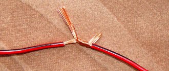
One of the most common examples of low-current cables is twisted pair (UTP). It consists of several wires twisted in pairs, combined into a common polyethylene sheath. Twisted pair cable most often becomes the basis for home or corporate networks. Such a cable is capable of transmitting various data - video, audio, etc. In addition, cables such as CAVEL, FTP, RG, SAT, SILICON REXANT are also used to build low-current networks.
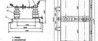
Cable laying in trays
STANDARDS AND REQUIREMENTS TYPES AND TYPES OF TRAYS
Tray placement of cable routes is implemented mainly in industrial premises and requires a special approach to the selection of structures and compliance with PUE standards during their design and installation.
Particular attention is paid to dissimilar lines and electrical circuits; deviation from safety requirements when placing them in trays is fraught with serious failures and risks of electrical installations failing.
IN WHAT CASES IS Cable Laying in Trays USED?
A tray is an open fireproof structure used for laying cables and wiring inside buildings and in outdoor installations.
In particular, according to the PUE standards, insulated, but without special armor, cables with a voltage of up to 1000 V and a cross-section of up to 16 mm2 are laid in them.
The upper limit of the cross-section and reliability of insulation is not limited; the use of trays is permissible for all cases of open installation, unless the rules stipulate otherwise (namely, mandatory installation in blind steel pipes).
This method is recommended to be chosen if necessary:
- open laying of a large number of wires in dry, damp or hot industrial premises (with the mandatory placement of the tray 2-2.5 m above the floor level and service area, depending on the requirements of the PUE clause 2.1.52);
- placing the cable in rooms with a chemically active or fire hazardous environment (unless the rules stipulate otherwise);
- laying wires and cable systems on vertical and horizontal sections of technical floors, in passages behind switchboards and transitions between them, basements of electrical machine rooms, in compressor and pump rooms.
The main advantages of this method include ease of maintenance and good preservation of the cable sheath (the product is not pulled through pipes and wears less, finding and replacing damaged areas is simplified).
Protection from external influences is not the main goal of installing trays, but it is still achieved to one degree or another.
Trays provide organized routing and cooling of large accumulations of wires and remove them at a safe distance from aggressive environments, heat sources or dangerous devices. Laying branches is possible at any site; with an increase in the number of wires and their presentation in trays, no problems arise.
The disadvantages are manifested in labor intensity and an increase in cost by at least 2 times in comparison with securing the cable to structures without the use of protective structures.
But in comparison with installation in pipes and other options chosen for high fire and moisture protection requirements, this method is cheaper.
The limitations taken into account also include the need for combination with other (closed) laying methods when organizing the lowering of trays to distribution boards.
STANDARDS, REQUIREMENTS AND FEATURES OF LAYING CABLES OF DIFFERENT TYPES
The main guidelines are the PUE standards (in particular, 2.1 and 2.3), SNiP 3.05.06-85 and GOST R 52868. These and other construction and electrical installation rules are taken into account when drawing up a project for laying trays, choosing their materials, design features and sizes.
The presence of a project and its strict adherence during installation is a mandatory requirement; any deviations are agreed upon separately.
The rules for the design of electrical installations allow the joint placement of wires for different purposes in trays with a total voltage of up to 440 V. The main guideline when checking the admission or prohibition of the joint installation of circuits for different purposes are clauses 2.1.15 and 2.1.16 of the PUE.
According to the norms, an exception is made in any case for:
- mutually redundant lines with different power sources;
- emergency and work lighting circuits with more than 8 wires and lighting circuits with different voltages (up to 42 V and above 42 V) without separate insulation;
- automation and fire alarm circuits, metering and measuring instruments, secondary communications and relay protection lines; stationary electrical networks with voltage up to 42 V, laid separately in accordance with TB requirements.
One-sided laying of low-current and power lines is permitted provided they are separated by non-flammable asbestos partitions. In this case, according to the norms, power lines are placed on top.
Redundant low-current cables are laid in different trays or also separated by partitions. Chaotic and arbitrary arrangement of cables with different voltages and purposes is prohibited.
General requirements include laying in one row, without rings, filling the free space by no more than 50-60%. Unarmored cables with voltages up to 1 kV can be laid in a single layer without gaps, multi-layered or in bundles with a diameter of no more than 100 mm and gaps of 20 m and above.
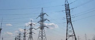
How to lay a power cable
Power cables are used to transmit three-phase current from utility facilities and industrial enterprises to end consumers of electricity. Modern solutions help optimize the scale of power grids and reduce the use of older generation overhead lines. Wire insulation with stitched polyethylene and aluminum lining help increase the service life of electrical networks.
Power cable installation methods
- open,
- hidden: in trenches, through pipes, trenchless,
- in trays.
They choose the method of placing the electrical network based on the objectives of the project, the characteristics of the external environment and the budget. For each method, the Electrical Installation Rules (EPR) provide recommended materials and work regulations.
Open way
When installing in an open manner, supports are used, for example, steel racks. Open laying can be done either manually or using a lever system: it all depends on the weight of the power cable. Heavy cables are moved using a winch and a roller system, while light cables are unrolled by hand and then laid out on support points. Supporting structures must be made of materials that prevent oxidation.
In order to protect the unarmored wire in places where it is rigidly attached to a metal surface, elastic gaskets are chosen. Power lines in plastic hoses or an armored casing are allowed by the PUE to be installed in an open manner without the use of gaskets.
A cable laid openly must be marked. On the marking labels they write down: the brand, its cross-section, voltage and line name. The tag material must be able to withstand exposure to water, sun and wind.
Trenching is the least expensive approach to installing power cable. To protect the electrical network from soil corrosion, wires with a sheath of cable yarn and steel armor are used.
Electrical installation rules (PUE) limit the number of cables in one trench (no more than 6) and determine the minimum permissible distance between wires (100-250 mm). If cables belonging to different organizations are laid in one trench, then the distance between them should be at least 0.5 m.
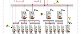
Distance between power and low-current cables PUE
Low-current networks are part of the engineering systems of buildings.
Any cable network can be called low-current if the cables carry not power, but information currents with a voltage of 12 V to 24 V and measured in milliamps.
The main requirements for low-current networks are their high reliability, correct operation without errors of various kinds and failures, low cost during construction and operation, and scalability.
Thanks to the use of low-current systems, it is possible to ensure the quality of all types of communications and the functioning of computer networks. Depending on the purpose and area of application, low-current systems can be divided into domestic and commercial.
Currently, low-current networks make it possible to provide and create:
- reception and distribution of terrestrial and satellite television;
- access to the telephone network;
- access to the global network;
- access to a wired broadcast network;
- security and fire systems (fire and burglar alarms, video surveillance);
- warning and alarm systems;
- access control systems for objects (gates, barriers, turnstiles);
- automated accounting and energy management systems (electricity meters, water meters, home automation);
- local area networks (LAN);
- intercoms (ATS);
- structured cabling systems (SCS).
Emergency lighting standards
- The illumination of surfaces when starting security lighting must be at least 10 lux for incandescent lamps and at least 15 lux for fluorescent analogues.
- Evacuation lighting should produce at least 0.5 lux for cramped spaces and narrow corridors. In open areas and large rooms, illumination of 0.2 lux is allowed.
- According to sanitary standards and rules, the following situations are considered equal to each other: the production area of one workshop is more than 150 square meters. m;
- there is a room in the building where more than 100 people are present at the same time;
- a room where there is no natural light and where there are from 50 to 100 people at the same time.
In all three of these cases, it is mandatory to place directional arrows on the evacuation routes, which are directed towards the emergency exit. They should be located on the walls or ceiling in the visibility zone of evacuating personnel at least every 25 meters, as well as at every turn. Instead of luminous arrows, it is permitted to use a decorative emergency lighting lamp with an arrow pattern, which is made in accordance with the state standard and is suitable for these purposes.
Ceiling emergency exit sign
- Regardless of the purpose, all emergency lighting must be connected to a backup power source and in no case depend on the main power supply. Emergency backup lighting of both types must necessarily complement each other and not depend on one another. To achieve this, each network is usually connected to its own emergency power supply.