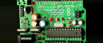
What is Arduino?
Arduino is a special tool that allows you to design electronic devices that have closer interaction with the physical environment in comparison with the same PCs, which actually do not go beyond virtual reality.
The platform is based on open source code, and the device itself is built on a printed circuit board with software embedded in it.
In other words, Arduino is a small device that provides control of various sensors, lighting systems, data reception and transmission.
Arduino includes a microcontroller, which is a microprocessor assembled on one circuit. Its specialty is its ability to perform simple tasks. Depending on the model, the Arduino device can be equipped with various types of microcontrollers.
There are several models of boards, the most common of them are UNO, Mega 2560 R3.
An equally important feature of the printed circuit board is the presence of 22 pins, which are located around the perimeter of the product. They are analog and digital.
The peculiarity of the latter is that it is controlled using only two parameters - a logical one or zero. As for the analog pin, there are many small regions between 1 and 0.
Today, Arduino is used to create electronic systems that can receive information from various sensors (digital and analog).
Arduino devices can work in conjunction with software on a computer or independently.
As for the boards, you can assemble them yourself or purchase a finished product. Arduino programming is done in the Wiring language.
READ ON THE TOPIC: Xiaomi Smart Home, review, equipment, connection and setup with your own hands, scenarios.
Smart home (control from Android smartphone)
This article will discuss the creation of a Smart Home system using an Arduino UNO controller controlled via an Android smartphone and a Bluetooth module HC-05.
The task is to create an Arduino sketch and an Android program that meets the necessary requirements.
From the hardware you need:
- Arduino UNO
- Bluetooth module HC-05
- 2-channel relay module 5V 10A
- Humidity and temperature sensor DHT-22
Then I started creating a sketch for the Arduino SMARTHOUSE.ino. A ready-made example was found on the Internet, but it did not fit the functionality, so I set about adding to it. My task is for the sketch to receive a command to turn on a certain relay and at the same time transmit readings from the humidity and temperature sensor. Having minimal programming knowledge, everything worked out for me and the program was written.
The most difficult thing remained to create applications for Android; for this I used the AppInventor 2 program.
General view of the program:
Features of the program are: the ability to automatically connect to a previously selected Bluetooth device, voice recognition of text, display of temperature and humidity in real time. Before you start using voice commands, you need to enter the command itself into the multi-colored fields using the smartphone keyboard and click the save button (the save button also remembers the connected device).
Next came the assembly of all components into a single system.
Connection HC-05:
DHT-22 connection:
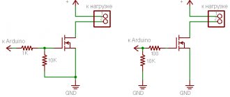
The load is connected to pins 8, 9, 10. If suddenly something is not clear with the connection, then you can look at all the pins from the sketch itself. After connecting all the components, you need to install and run my program SMARTHOUSE.apk
After installation, turn on Bluetooth on your smartphone and connect to the HC-05 module, and turn on our program.
After launch, click the search button and see a window with a list of available devices, you need to select HC-05.
When the choice is made, you need to press the CONNECT and SAVE button, the bluetooth device address will appear in the green window.
And now, when we press the red switches, we can send a signal to the pin we need (a long press on the switch button sends a command to turn off the load). Temperature and humidity readings from the DHT-22 sensor will appear under the “enable all” and “switch off all” buttons.
Source https://arduino-ua.com/art55-ymnii-dom-1-ypravlenie-s-android-smartfona
What does Arduino control?
Thanks to the large number of pins on the printed circuit board, it is possible to connect many different devices to Arduino, namely:
In addition, a set of sensors is connected to Arduino depending on the tasks assigned to the system. As a rule, sensors for light, smoke and air composition, magnetic field, humidity, temperature and others are installed.
Thanks to this feature, Arduino becomes a universal device - “a brain device with the ability to be configured taking into account the tasks at hand.
How the system works
The Arduino device works as follows. Information collected from various sensors in the home is sent wirelessly to a tablet or PC. Next, using special software, the data is processed and a specific command is executed.
The main function is performed by a central sensor, which you can purchase or assemble yourself. The connectors on the boards are standard, which greatly simplifies the selection of components.
Nutrition
The Arduino is powered via a USB connector or from an external power supply. The voltage source is determined automatically.
If you select the option with external power supply not via USB, you can connect a battery or power supply (voltage converter). In the latter case, the connection is made using a 2.1 mm connector with a “+” on the main contact.
The wires from the battery are connected to various terminals of the power connector - Vin and Gnd.
For normal operation, the platform requires a voltage of 6 to 20 Volts. If the parameter drops below 7 volts, the 5V pin may have less voltage and risk a failure.
If you supply 12 V, the voltage regulator may overheat and damage the board. For this reason, the optimal level is power supply using 7 - 12 V.
Unlike previous types of boards, the Arduino Mega 2560 works without the use of a USB FTDI microcontroller. To ensure information exchange via USB, a USB-to-serial converter programmed for the converter is used.
POPULAR WITH READERS: What is a CLAP smart home.
The Arduino has the following power pins:
- 5V - used to supply voltage to the microcontroller, as well as other elements of the printed circuit board. The power supply is adjustable. Voltage is supplied via a USB connector or from the VIN pin, as well as from another 5 Volt power source with the ability to regulate.
- VIN - used to supply voltage from an external source. The output is necessary when it is not possible to supply voltage via a USB connector or other external source. When voltage is applied to the 2.1mm jack, this input is used.
- 3V3 is a pin whose voltage is a consequence of the operation of the FTDI chip itself. The maximum current consumption level for this element is 50 mA.
- GND - grounding terminals.
The circuit diagram of the board in pdf format can be viewed HERE.
Connection
Arduino capabilities allow you to connect a group of devices that provide stable communication with a PC, as well as other system elements - microcontrollers or the same Arduino boards.
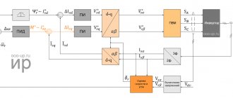
The ATmega 2560 model is distinguished by the presence of 4 ports through which data can be transferred for TTL and UART. A special ATmega 8U2 chip on the board transmits the interface (one of them) via a USB connector. In turn, programs on the PC receive virtual COM.
There are nuances here that depend on the type of operating system:
- If Linux is installed on the PC, recognition occurs automatically.
- If you are using Windows, you will need an additional .inf file.
Using the monitoring utility, you can send and receive information in text format after connecting to the system.
Flashing TX and RX LEDs indicate data transmission. A special Software Serial library is used to send information sequentially.
Features of the ATmega 2560 include the presence of SPI and I2C interfaces. In addition, Arduino includes the Wire library.
How the Arduino system works
The controller receives and transmits data through ports. In total, there are over a dozen different ports on the standard board, the number of which can be increased by attaching another similar controller. All Arduino ports are divided into two types for connecting various devices:
- Analog.
- Digital.
Arduino connection diagram
You should initiate the operation of analog ports by using the pin-Mode function in the downloaded program:
- Select the number of the desired pin.
- Set the mode to “Receive data” (OUTPUT) or “Transmit data” (INPUT).
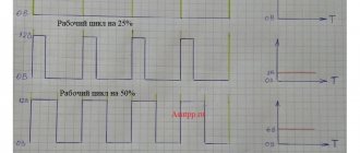
Pulse width digital modulators (PWM) have a more intelligent interface that allows them to both receive and transmit the desired data. On the board, PWM ports are indicated by a tilde (~) or the abbreviation PWM. When connecting external sensors and devices to the controller board, the technical parameters of the ports should also be taken into account. They are able to issue:
- 5 volts voltage.
- 0.02 ampere current.
If you use batteries or a battery with a voltage of over 12 volts as a power supply for the board, it may overheat and fail. If the supply voltage decreases to 6-7 volts, on the contrary, the output of the port may be less than 5V, which, in turn, will cause malfunctions. Collected into a single complex, devices, detectors and sensors transmit information to the Arduino processor, and from there, through a connected GPS or GSM module, it is sent to a computer or other control device with installed software, which makes a decision on issuing a specific command. This could be turning a household appliance on or off, or transferring data to the home owner’s mobile device.
Project development
There are many Arduino devices on the market today, with different configurations. But there is no universal solution “for all occasions”. Depending on the task at hand, each kit is selected individually. To avoid mistakes, project development is required.
What projects can be created on Arduino?
Arduino allows you to create many unique projects. Here are just a few of them:
- Solving a Rubik's cube (the system solves it in 0.887 s);
- Controlling humidity in the basement;
- Creation of unique paintings;
- Sending messages;
- Balancing robot on two wheels;
- Sound spectrum analyzer;
- Origami lamp with capacitive sensor;
- Robotic arm controlled by Arduino;
- Writing letters in the air;
- Flash control and much more.
We select the equipment for the project using the example of Arduino Mega 2560 R3
To create a full-fledged Smart Home system and perform its assigned functions, it is important to correctly approach the configuration and selection of equipment.
What's included in the package?
If your goal is a “Smart Home” based on Arduino, you need to prepare the following equipment - the Mega 2560 R3 board itself, an Ethernet module (ENC28J60), a motion sensor, as well as other sensors and controllers.
In addition, it is worth preparing a twisted pair cable, a resistor, a relay, a switch and a cable for the Ethernet module.
Additional tools are also needed - screwdrivers, soldering irons, etc.
Please note that you should buy kits for installing the system at certified points. This is due to the fact that the project uses electricity, and the use of counterfeits can lead to a decrease in safety.
All programs for adaptation can be found online on the official Arduino website https://arduino.ru. When choosing sensors, you should focus on the tasks that the Smart Home must solve.
Typically, motion, temperature, door opening and light sensors are required. The role of a door opening sensor can be performed by a regular reed switch.
The board is flashed using special software designed for various operating systems, including a USB cable. In this case, there is no need for programmers.
As for the software used in Arduino, it is written in C language. There are certain restrictions on the number of bytes, but the current memory is sufficient to implement the task.
Creating a project on Arduino
We will show the process of creating and setting up an Arduino “smart home” using the example of a system that will include the following functions:
- outdoor and indoor temperature monitoring;
- window state tracking (open/closed);
- monitoring weather conditions (clear/rainy);
- generation of a sound signal when a motion sensor is triggered if the alarm function is activated.
We will configure the system in such a way that the data can be viewed using a special application, as well as a web browser, that is, the user can do this from any place where there is Internet access.
Abbreviations used:
- "GND" - grounding.
- "VCC" - power supply.
- "PIR" - motion sensor.
Necessary components for making a smart home system
For the Arduino smart home system you will need the following:
- Arduino microprocessor board;
- Ethernet module ENC28J60;
- two temperature sensors brand DS18B20;
- microphone;
- rain and snow sensor;
- Motion Sensor;
- reed switch;
- relay;
- resistor with a resistance of 4.7 kOhm;
- twisted pair cable;
- Ethernet cable.
All components cost approximately $90.
To produce a system with the functions we need, we will need a set of devices costing about $90
Beginning of work
Once the necessary equipment is prepared and the project is developed, you can begin to complete the task.
Stages
When organizing a Smart Home system based on Arduino, you should follow the following algorithm:
- Installation of program code;
- Application configuration for the device used;
- Port forwarding (for router);
- Carrying out tests;
- Making edits and so on.
The Internet has all the necessary software for the equipment used - just download it from the official website and install it (see link above).
The application allows you to see information about sensors. If required, the IP address settings can be changed.
Sequence of actions when connecting to a computer
To get started with Arduino on Windows, follow these steps:
- Prepare the necessary equipment - USB cable and Arduino.
- Download the program from arduino.cc/en/Main/Software.
- Connect the board using a USB cable. Make sure the PWR LED lights up.
- Install the necessary set of drivers to work with Arduino. At this stage, you should start the driver installation and wait for the process to complete.
Then click on the “Start” button and go to the control panel. There, open the “System and Security” tab and select the “System” section. After opening the window, select “Device Manager”, click on the Arduino name and use the right mouse button to specify the driver update command. Find the line “Browse my computer for Driver software!”, click on it and select the appropriate driver for your board type - ArduinoUNO.inf (located in the drivers folder). It could be UNO, Mega 2560 or another. - Launch the Arduino development environment by double-clicking on the application icon.
- Open the finished example (File - Examples - 1.Basics - Blink).
- Select a board. To do this, go to the Tools section, and then to the Board Menu.
- Install the serial port (you can find it by unplugging and plugging the cable).
- Download the sketch in Arduino. Click on “Upload” and wait for the TX and RX LEDs on the board to blink. Finally, the system shows that the download was successful. A few seconds after completion of work, LED 13 L should light up (it will flash orange). If so, the system is ready to perform tasks.
Working with a router
For the Smart Home to function properly, it is important to handle the router correctly. Here you need to perform the following steps - open the configuration, specify the Arduino IP address, for example, 192.168.10.101 and open port 80.
Afterwards you need to assign a domain name to the address and proceed to the project testing process. Please note that for such a system it is prohibited to use a public IP address, because in this case there is a high risk of hacking through the Network.
What solutions does Arduino offer?
Sensors and devices compatible with Arduino are produced by many manufacturers, so the range of components for the Smart Home system on Arduino is impressive:
- Sensors for monitoring temperature, light at different times of the day, humidity, precipitation and atmospheric pressure.
- Motion sensors.
- Emergency sensors.
- Other devices and remote controls.
The Arduino Start kit (from most manufacturers - StarterKit) includes some indicators and sensors.
To execute commands sent by the Arduino-based Smart Home system, the following is required:
- relays and switches;
- valves;
- electric motors;
- 3-way valves with servo drive;
- dimmers.
Expanding capabilities on Arduino
One of the capabilities of a smart home is visualization of the state of automation and processes occurring in the system. To do this, it is recommended to use a separate server that provides state processing (the Node.js program can be used).
The mentioned software technology is used to solve Internet problems, therefore, to visualize the “Smart Home”, the Java Script language is used (it is with its help that the processor and server are created). The results can be seen on your computer or PC screen.
To implement your plan, a laptop, a regular PC or a Raspberry Pi will be suitable. The use of such a system allows you to increase its capabilities. So, if the Arduino board has a small amount of memory, there are no such restrictions on the server. The program is written in such a way as to provide full control of the platform.
If desired, you can set an algorithm that will record the fact that a person is in the house and collect this information. If the owner returns around 5:30 pm every day, the boiler or heating devices can be turned on an hour before. Upon arriving home, a person finds himself in a warm building with hot water.
The program can remember the time when the owner goes to rest and turn off the water heating. There are many such nuances that, if necessary, are introduced into the program. It is the presence of an external PC that gives great opportunities to the Arduino controller.
Visualization of a “smart home” and expanding capabilities on Arduino
Of course, to visualize the processes of a “smart” home, one could use an LCD display or any digital display. But still, this is not a good solution for a “smart” home.
To visualize automation processes and states on the Arduino platform, it is best to use a separate state processing server. This server can be implemented using Node.js software technology, which allows you to implement any server, including one for processing the states of the Arduino board.
Node.js is used to solve Internet of Things problems, so it is definitely suitable for visualizing smart home automation. It is enough to create a server and a handler in JavaScript , and you can display the result in the browser of your computer or tablet.
Single board microcomputer Raspberry Pi
You can use a Raspberry Pi microcomputer or a regular desktop computer or laptop as the server hardware. At the same time, the capabilities of the automation system itself are expanded.
If the Arduino board has a limited amount of physical memory, then on the server this amount is unlimited. The server program itself can be written in such a way that it will completely control the Arduino platform.
For example, we can expand the functionality of our “smart” home and bring it closer to a smart home without quotes. It is possible to write an algorithm that will keep statistics of the owner’s presence in the house and his return home. If the owner usually returns home around 17:30, then an hour before the owner can turn on the boiler to heat the water. Also, focusing on this time, you can turn on the heating devices in advance so that you return to a warm house, and not to one where the temperature is 10 degrees lower due to saving electricity in the absence of the owners. The program can understand when the owners usually go to bed and stop heating the water in advance, since no one will use it until the morning. And there can be many such nuances. It is an external computer that can provide advanced “brains” to the Arduino controller , which will turn into more of an actuator.
Communication with Arduino
To know what actions to perform, the processor must receive the appropriate command. Communication is carried out using a special language, which is adapted for working with Arduino and is quite simple. If desired, it is easy to work with even without programming skills.
Formatting and sending a message to the controller is called programming. To simplify the process, the Arduino IDE has been developed, which includes many programs. Studying them allows you to get a lot of useful information about working with Arduino.
How can you manage?
As noted, the Node.js server allows you to connect equipment in your home. One of the ways to manage processes is cloud services on the Internet. In this case, you can turn on the heating or boiler one to two hours before arrival.
Another way is to control using messages (MMS or SMS). This option is relevant when there is no connection to the Internet. One of the advantages of the system is the ability to obtain information about a force majeure situation (for example, a leak). The Edison board from Intel helps here.