GSM and GPRS modules for Arduino
The GSM and GPRS module in Arduino projects allows you to connect to remote autonomous devices via regular cellular communications.
We can send commands to the device and receive information from it using SMS commands or through an Internet connection opened via GPRS.
In this article we will look at the most popular modules for Arduino, understand the connection and look at programming examples.
GSM GPRS in Arduino
GSM GPRS modules
The GSM module is used to expand the capabilities of regular Arduino boards - sending SMS, making calls, exchanging data via GPRS. There are different types of modules, the most commonly used are SIM900, SIM800L, A6, A7.
Description of the SIM900 module
The SIM900 module is used in various automated systems. Using the UART interface, data is exchanged with other devices. The module provides the ability to make calls and exchange text messages. The module is implemented on the SIM900 component, created by SIMCom Wireless Solution.
Specifications:
- Voltage range 4.8-5.2V;
- In normal mode, the current reaches 450 mA, the maximum current in pulse mode is 2 A;
- 2G support;
- Transmission power: 1 W 1800 and 1900 MHz, 2 W 850 and 900 MHz;
- There are built-in TCP and UDP protocols;
- GPRS multi-slot class 10/8;
- Operating temperature from -30C to 75C.
Using the device, you can track the route of a vehicle together with GLONASS or GPS device. The ability to send SMS messages is used in wireless alarms and various security systems.
Description of the SIM800L module
The module is based on the SIM800L component and is used for sending SMS, making calls and exchanging data via GPRS. A micro SIM card is installed in the module.
The device has a built-in antenna and a connector to which you can connect an external antenna. Power to the module is supplied from an external source or through a DC-DC converter.
Control is carried out using a computer via UART, Arduino, Raspberry Pi or similar devices.
Specifications:
- Voltage range 3.7V – 4.2V;
- Support for 4-band network 900/1800/1900 MHz;
- GPRS class 12 (85.6 kB/s);
- Maximum current 500 mA;
- 2G support;
- Automatic search in four frequency ranges;
- Operating temperature from –30C to 75C.
Description of module A6
The A6 module was developed by AI-THINKER in 2021. The device is used for exchanging SMS messages and exchanging data via GPRS. The board is characterized by low power consumption and small size. The device is fully compatible with Russian mobile operators.
Specifications:
- Voltage range 4.5 – 5.5V;
- Power supply 5V;
- Operating temperature range from -30C to 80C;
- Maximum current consumption 900mA;
- GPRS Class 10;
- Supports PPP, TCP, UDP, MUX protocols.
The module supports microsim cards.
Description of module A7
A7 is the latest module from AI-THINKER. Compared to its predecessor, the A6 has built-in GPS, allowing for a simplified design of the device.
Specifications:
- Operating voltage range 3.3V-4.6V;
- Supply voltage 5V;
- Frequencies 850/900/1800/1900 MHz;
- GPRS Class 10: Max. 85.6 kbit;
- Echo and noise suppression.
The device supports microSIM cards. The module supports exchanging calls, exchanging SMS messages, transmitting data via GPRS, receiving signals via GPS.
Where to buy GSM modules for Arduino
As usual, before you start, here are some tips and useful links to Aliexpress sellers.
Connecting GSM GPRS shield to Arduino
In this section we will look at the issues of connecting GSM modules to the Aduino board. Almost all examples are based on the Arduino Uno, but most examples will also be used for Mega, Nano, etc. boards.
Connecting the SIM800 module
To connect, you need an Arduino board, a SIM800L module, a step-down voltage converter, connection wires and a 12V battery. The SIM800L module requires a non-standard Arduino voltage of 3.7V; this requires a step-down voltage converter.
The pinout of the SIM800 module is shown in the figure.
The Arduino board must be connected to the computer via a USB cable. Connect a 12V battery through a converter: -12V to Arduino ground, from ground to negative converter, +12V to positive converter. The outputs from the TX and RX module must be connected to pins 2 and 3 on the Arduino. Multiple modules can be connected to any digital pins.
Connecting module A6
The A6 module is cheaper than SIM900 and is very easy to connect to Arduino. The module is powered by a voltage of 5V, so the connection does not require additional voltage-reducing elements.
To connect, you will need an Arduino board (in this case, Arduino UNO is considered), an A6 GSM module, and connecting wires. The connection diagram is shown in the figure.
The RX pin from the GSM module must be connected to TX on the Arduino board, the TX pin must be connected to the RX pin on the Arduino. The ground from the module is connected to the ground on the microcontroller. The Vcc pin on the GSM module must be connected to PWR_KEY.
Connection using GSM-GPRS shield
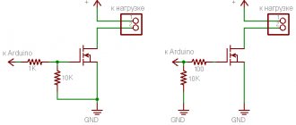
Before connecting, it is important to pay attention to the shield's supply voltage. The current at the time of a call or sending data can reach values of 15-2 A, so you should not power the shield directly from the Arduino.
Before connecting to Arduino, you need to install a SIM card on the GSM-GPRS shield. You also need to install the TX and RX jumpers, as shown in the figure.
The connection is made as follows - the first contact (yellow wire in the figure) from the shield must be connected to TX on the Arduino. The second pin (green wire) connects to RX on the Arduino. The land from the shield is connected to the land from the aruino. Power is supplied to the microcontroller via a USB cable.
The layout of the connection between the shield and the Arduino board is shown in the figure.
To work, you will need to install the GPRS_Shield_Arduino library.
To check the correctness of the assembled circuit, you need to do the following: connect RESET and GND on the Arduino (this will lead to data being transferred directly from the shield to the computer), insert the SIM card into the shield and turn on the power of the shield. The Arduino board needs to be connected to the computer and the power button pressed. If everything is connected correctly, the red LED will light up and the green LED will blink.
Brief description of interaction via AT commands
AT commands are a set of special commands for the modem, consisting of short text strings. In order for the modem to recognize the command given to it, the lines must begin with the letters at. The string will be accepted when the modem is in command mode.
AT commands can be sent either using communications software or manually using the keyboard.
Almost all commands can be divided into 3 modes - test, in which the module answers whether it supports the command; read – output current command parameters; write – new values will be written.
List of most used AT commands:
- AT – to check whether the module is connected correctly. If everything is OK, OK is returned.
- A/ - repeat the previous command.
- AT+IPR? – obtaining information about the port speed. The answer will be +IPR: 0 OK (0 in this case is automatic).
- AT+ICF? – transmission setting. The response will be +ICF: bit, parity.
- AT+IFC? – transmission control. The answer will be +IFC: terminal from module, module from terminal (0 – no control, 1 – software control, 2 – hardware control).
- AT+GCAP – shows the capabilities of the module. An example response is +GCAP:+FCLASS,+CGSM.
- AT+GSN – obtaining module IMEI. Example answer 01322600XXXXXXXX.
- AT+COPS? – shows available operators.
Source: https://ArduinoMaster.ru/datchiki-arduino/gsm-gprs-modul-arduino/
FEATURES OF CHINESE TRADE
Be careful, sellers on Aliexpress have a very bad habit of writing something like 2pcs in the product name, which seems to hint that these are two pieces of the item for the specified price.
But this is a little different, and is designed to stimulate impulse purchases. For example, in the description of the Arduino Uno board it is written that “UNO R3 MEGA328P ATMEGA16U2 + USB Cable (1UNO R3 + 1 cables) Best prices & Free shipping!!!”, the price is $9.98 and it is added that this is a lot (2 pieces/lot) .
At first glance it seems that these are TWO (profit!!!) Arduino Uno boards. But in fact, behind 2 pieces/lot lies exactly what is written in the title and, a little lower in the description (to the credit of the Chinese - in huge letters). Exactly:
— Arduino Uno — 1 piece — USB cable — 1 piece Total: TWO pieces
Those. in this case, one lot is a board + cable. The only excuse for the seller is that the price is average in the market.
What else did I not like about this order? Out of a set of two relays, only one block came. The seller responds sluggishly, for a long time, but in the end he agreed to send the second block.
Otherwise everything is tolerable. Delivery took about a month, the packaging was a rather hard cardboard box wrapped with tape. Everything inside is in antistatic bags, the Ethernet shield is pinned onto polypropylene (?) pads so that the contacts do not bend.
Everything arrived in good condition. But taking into account some kind of inhibition of the seller, and even these relays, I don’t think that I will buy anything else from him.
Controlling Arduino via the Internet
DetailsCategory: ArduinoPublished 11/10/2015 16:35Author: AdminViews: 7300
This article describes the process of “communicating” with Arduino via the Internet.
Commands are sent using ajax requests, these requests are received by a python script which transmits them through a serial port connection to the arduino board.
Of course, you can purchase a ready-made Ethernet board for arduino, connect the cable and upload the finished program. But you can do everything differently.
And for this we need:
http server;
python interpreter.
Control code in Java Script//Port to which the Arduino is connected var serialPort = 'COM5'; //directly control function var Arduino = function(command, callback){ $.get('c.py',{ c:command, p:serialPort }, callback); }
In this code, the only thing you need to change is the name of the port, set to the one on which your arduino is sitting. You can find out where your Arduino is by looking in the Windows Device Manager. This name is passed by the script to the phyton interpreter which connects to the arduino.
For example, if we called our Aruduino() function with parameters “123”, then a request like “index.html?с=123&p=COM5” will be created, which is used in a python script. What is it?#!/Python33/python.exe import serial import cgi print (“STATUS: 200 OK “) req = cgi.FieldStorage(); ser = serial.Serial(req['p'].
value, 9600, timeout=1) ser.write(bytes(req['c'].value,'latin')) ser.close() print (“ok”) Basically it just accepts the “c” parameter, and sends it to serial port “p” and then outputs “ok” Code for Arduino #include Servo myservo; void setup() { Serial.begin(9600); } String getParam(){ String re; while(Serial.
BT Voice Control for Arduino
Using this application, you can send and receive data from devices such as an ultrasonic sensor connected to the Arduino via Bluetooth. HC-05 module was used to connect the Arduino device to the mobile phone via Bluetooth. Once connected, the ultrasonic sensor will transmit the distance to the nearest object and this will be displayed on the mobile phone in this application.
The Arduino was programmed with a list of recognized commands such as Forward, Backward, Left, Right, and Stop. It is important to know that the ultrasonic sensor sends the distance to the nearest object to the Arduino and then sends it to the application using the HC-05 Bluetooth module.
Rating on Google Play: 4.4 out of 5
Number of downloads: more than 10,000
Ethernet shield w5100 load management
Arduino WEB control
| Smoke detector | 0 |
| Temperature | 0 °C |
| Humidity | 0 % |
Relay No. 1 Relay No. 2 Relay No. 3 Relay No. 4
Don't forget that the file must be saved in "utf-8" encoding. It's time to draw the final diagram of our project. (Sorry for the paint, if you draw it better, I’ll be glad to post it =))
Explanation of the diagram. We connect all this to the Ethernet Shield W5100 board. Here we have it like a “slice of cheese”, and a piece of Arduino UNO bread. Temperature and humidity sensor DHT-11 is connected to digital input 7.
Gas and smoke sensor to analog input A0. Load control relays (in my case, LEDs) are connected to digital outputs 2, 3, 5, 6. As you understand, you can connect any sensors.
I just connected what was at hand.
All that remains is to figure out the firmware. The firmware from previous articles has been changed quite a bit. I won’t describe anything separately. Here is all the firmware code at once.
Code
#include #include #include #include #define DHT11_PIN 7
#define REQ_BUF_SZ 20
dht11 DHT; File webFile; char HTTP_req[REQ_BUF_SZ] = {0}; // buffered HTTP request stored as NULL terminated string char req_index = 0; // index into HTTP_req buffer byte mac[] = { 0xDE, 0xAD, 0xBE, 0xEF, 0xFE, 0xED};
IPAddress ip(192, 168, 0, 20);
EthernetServer server(80); bool pin1; bool pin2; bool pin3; bool pin4; void setup() { pinMode(2, OUTPUT); pinMode(3, OUTPUT); pinMode(5, OUTPUT);
pinMode(6, OUTPUT);
SD.begin(4); Ethernet.begin(mac, ip); server.begin(); pin1 = pin2 = pin3 = pin4 = 0;
}
void loop() { // listen for incoming clients EthernetClient client = server.available();
if (client) {
// an http request ends with a blank line boolean currentLineIsBlank = true; while (client.connected()) { if (client.available()) { char c = client.
read(); if (req_index
println(“Content-Type: text/html”); client.println(“Connnection: close”); client.println(); webFile = SD.open(“index.htm”); } else if (StrContains(HTTP_req, “GET /favicon.ico”)) { webFile = SD.open(“favicon.ico”); if (webFile) { client.println(“HTTP/1.1 200 OK”); client.
println(); } } else if (StrContains(HTTP_req, “GET /temp.png”)) { webFile = SD.open(“temp.png”); if (webFile) { client.println(“HTTP/1.1 200 OK”); client.println(); } } else if (StrContains(HTTP_req, “GET /humid.png”)) { webFile = SD.open(“humid.
png"); if (webFile) { client.println(“HTTP/1.1 200 OK”); client.println(); } } else if (StrContains(HTTP_req, “GET /flame.png”)) { webFile = SD.open(“flame.png”); if (webFile) { client.println(“HTTP/1.1 200 OK”); client.
println(); } } else if (StrContains(HTTP_req, “GET /my.css”)) { webFile = SD.open(“my.css”); if (webFile) { client.println(“HTTP/1.1 200 OK”); client.println(); } } else if (StrContains(HTTP_req, “ajax_flame”)) { client.println(“HTTP/1.1 200 OK”); client.
println(“Content-Type: text/html”); client.println(“Connection: keep-alive”); client.println(); int smoke_gas = 0; //pin on which the MQ-2 is connected int sensorReading = analogRead(smoke_gas); int chk; chk = DHT.read(DHT11_PIN); client.print(sensorReading); client.print(“:”); client.
print(DHT.temperature); client.print(“:”); client.print(DHT.humidity); client.print(“:”); client.print((digitalRead(2)) ? “1” : “0”); client.print(“:”); client.print((digitalRead(3)) ? “1” : “0”); client.print(“:”); client.print((digitalRead(5)) ? “1” : “0”); client.print(“:”);
client.print((digitalRead(6)) ? “1” : “0”);
} else if (StrContains(HTTP_req, “setpin?pin=1”)) { pin1 = !pin1; digitalWrite(2, pin1); client.println(“HTTP/1.1 200 OK”); client.println(“Content-Type: text/html”); client.println(“Connnection: close”); client.
println(); } else if (StrContains(HTTP_req, “setpin?pin=2”)) { pin2 = !pin2; digitalWrite(3, pin2); client.println(“HTTP/1.1 200 OK”); client.println(“Content-Type: text/html”); client.println(“Connnection: close”); client.
println(); } else if (StrContains(HTTP_req, “setpin?pin=3”)) { pin3 = !pin3; digitalWrite(5, pin3); client.println(“HTTP/1.1 200 OK”); client.println(“Content-Type: text/html”); client.println(“Connnection: close”); client.
println(); } else if (StrContains(HTTP_req, “setpin?pin=4”)) { pin4 = !pin4; digitalWrite(6, pin4); client.println(“HTTP/1.1 200 OK”); client.println(“Content-Type: text/html”); client.println(“Connnection: close”); client.
println();
}
if (webFile) { while (webFile.available()) { client.write(webFile.read()); // send web page to client } webFile.
close(); } req_index = 0; StrClear(HTTP_req, REQ_BUF_SZ); break; } if (c == ' ') { // you're starting a new line currentLineIsBlank = true; } else if (c != ' ') { // you've gotten a character on the current line currentLineIsBlank = false; } } } // give the web browser time to receive the data delay(1); // close the connection: client.stop(); }
}
void StrClear(char *str, char length) { for (int i = 0; i
}
char StrContains(char *str, char *sfind) { char found = 0; char index = 0; charlen; len = strlen(str); if (strlen(sfind) > len) { return 0; } while (index
}
Video of this project.
Archive with pictures for sensor names. Download. The files “my.css” and “index.htm” are also loaded into the root of the memory card. We unpack the pictures and put them there too.
By the way! If you happen to be a talented web designer and can suggest a different and more correct page design option, we will be glad to hear from you.
Z.Y. Small spoiler. An interesting project is already in the process of preparation. It will be for those who take care of their figure or simply watch their weight. So wait, and soon you will understand everything yourself) Z.Y.Y. Changes and additions have been made. Now from our page you can adjust the power using the slider. Read.
List of electronic components
NameTypeQuantityStore
| Arduino | UNO R3 | 1 | Find |
| Ethernet Shield | W5100 | 1 | Find |
| Temperature and humidity sensor | DHT-11 | 1 | Find |
| Smoke and gas sensor | MQ-2 | 1 | Find |
| Relay module | 4 channels | 1 | Find |
| Wires Dupont Male-Mama | Wires Dupont Male-Mama | 6 | Find |
| Cashback on Aliexpress |
Source: https://TehnoPage.ru/ethernet-arduino-control
Lesson 10. Access control. RFID-rc522 + Servo + Arduino
In this lesson we will learn how to make a simple system that will unlock a lock using an electronic key (Tag).
In the future, you can refine and expand the functionality. For example, add the function “adding new keys and removing them from memory.” In the base case, let's consider a simple example where a unique key identifier is pre-set in the program code.
In this tutorial we will need:
To implement the project we need to install the libraries:
- RFID Library for MFRC522.
Assembly:
1) The RC522 RFID module is connected to the arduino using male-female wires in the following sequence:
Learn more about connecting the Rfid module.
2) Now you need to connect a Buzzer, which will sound a signal if the key works and the lock opens, and a second signal when the lock closes.
We connect the buzzer in the following sequence:
ArduinoBuzzer
| 5V | VCC |
| GND | GND |
| pin 5 | IO |
3) A servo drive will be used as the unlocking mechanism.
Any servo drive can be selected, depending on the size you require and the force that the servo drive creates. The servo has 3 pins: Arduino Servo
| 5V* | Red (Central) |
| GND | Black or Brown (Left) |
| pin 6 | White or Orange (Right) |
*It is recommended to power the servo drive from an external power source; if you power the servo drive from the Arduino, interference and interruptions in the operation of the Arduino may occur. This can be organized using a 9V power supply and a combined 5V, 3.3V stabilizer.
You can see more clearly how we connected all the modules in the picture below:
Now, if everything is connected, you can proceed to programming.
Sketch:
#include #include #include // “RFID” library. #define SS_PIN 10 #define RST_PIN 9 MFRC522 mfrc522(SS_PIN, RST_PIN); unsigned long uidDec, uidDecTemp; // to store the tag number in decimal format Servo servo; void setup() { Serial.begin(9600); Serial.println(“Waiting for card...”); SPI.begin(); // SPI initialization / Init SPI bus. mfrc522.PCD_Init(); // initialization MFRC522 / Init MFRC522 card. servo.attach(6); servo.write(0); // set the servo to a closed state } void loop() { // Search for a new label if ( ! mfrc522.PICC_IsNewCardPresent()) { return; } // Select a label if ( ! mfrc522.PICC_ReadCardSerial()) { return; } uidDec = 0; // Issuing the serial number of the tag. for (byte i = 0; i Let’s look at the sketch in more detail:
In order to find out the UID of the card (Tag), you need to write this sketch into arduino, assemble the circuit outlined above, and open the Console (Serial Port Monitoring). When you touch the RFID tag, the console will display a number
The resulting UID must be entered in the following line:
if (uidDec == 3763966293) // Compare the Uid of the tag, if it is equal to the given one, then the servo drive opens the valve.
Each card has a unique identifier and is not repeated. Thus, when you present the card whose identifier you set in the program, the system will open access using a servo drive.
Video:
Source: https://lesson.iarduino.ru/page/kontrol-dostupa-rfid-rc522-servo-arduino/
Controlling Arduino from a computer
Connecting Arduino with a computer is very simple. Data is transmitted via a virtual RS-232(COM) port.
So let's move on to action. The three LEDs will be controlled from the keyboard by pressing the left and right keys. We light the first LED and press the left key, the burning LED goes out, and the one to the left of it lights up.
When the LED is in the extreme position, pressing in the same direction will switch to the LED on the opposite side.
On the computer, the control program will display the position of the lit LED.
The circuit with LEDs is extremely simple. LED1-3 LEDs connected to PWM pins. PWM is required for the fade effect.
R1 is a two hundredth resistor. To limit the current passing through the LED, otherwise the diode can burn out.
A small program for Arduino. (Download)
// Serial LED control // compblog.vlukyanov.com //Declare variables. int pin[] = {3, 5, 6}; // Declare an array containing the pin numbers int i = 0; // Variable for determining the current position of the lit LED int prev_i = 0; // Variable for remembering the previous LED // Setting up the Arduino void setup() { // Run a loop in which we define pins 3,5,6 as output for (int t = 0; t { pinMode(pin[t], OUTPUT) ; } Serial.begin(9600); // Initialize data retransmission via the COM port at a speed of 9600 baud } void loop() { // Start the loop without any action // Only when the data arrives at the COM port will the program continue execution this line while (Serial.available() == 0); // Data has arrived, read it into the variable ii = Serial.read(); // Gradually extinguish the previous LED, lowering the brightness from 255 to 0; for (int j= 255; j > 0; j–) { analogWrite(pin[prev_i],j); delay(1); // Small delay } analogWrite(pin[prev_i],0); // Finally turn off the LED // Arrived value i use to turn on the next LED for (int j=0; j { analogWrite(pin ,j); delay(1); } // We remember the value of the LED so that we can turn it off later when a new value appears on the COM port prev_i = i; }
Now we need a program on the computer that will send the necessary data to the COM port and display the data on the screen. Processing will work well. The Arduino IDE is based on processing, so they are very similar both in appearance and in syntax.
Also a fairly simple program in Processing. (Download)
// Serial LED control // compblog.vlukyanov.com import processing.serial.*; // connect the library for communication via the COM port // in the Arduino IDE this is done by default, here you need to do it additionally int value = 1; // a variable that will be sent to the COM port for Arduino Serial port; // variable indicating the port PFont f; // variable for the font void setup() { size(500,500); // create a window 500 by 500 px f = createFont(“Colibri”, 15,true); // define the font for this window port = new Serial(this, “COM5”, 9600); // set the port parameters, I have the fifth one } void draw() { // create a window background(0, 0, 0); // black background for the window textFont(f,200); // create text text(value-1,200,300); // display the value of the value variable in the center } void keyPressed() { // process key presses // the value variable is shifted from the zero position by 2 so as not to push it into minus if (keyCode == LEFT) { // when the key is pressed to the left value = value + 1; // increase value by 1 if ( value > 4 ) value=2; // if it is outside the third LED, reset the value to 2 port.write(value-2); // and send this value to the COM port } else if (keyCode == RIGHT) { // when the right key is pressed value = value – 1; // decrease value by 1 if ( value port.write(value-2); // and send this value to the COM port } else { } // otherwise do nothing }
Everything is relatively simple. The program on the computer transmits digital values to the Com port, Arduino turns off the current LED and lights up the LED with the number received through the port.
Source: https://compblog.VLukyanov.com/?p=344
Easily control your Arduino via the web
This article is intended for beginners. Here we will describe how to send commands from a web application using ajax requests to a phyton script, which will transmit them via serial port directly to our arduino.
You bought yourself an Arduino, tried a few examples, played with sketches. But this is not enough for you, you want to manage, manage all this goodness via the Internet.
The easiest way is to purchase a nameplate with an Ethernet port and connect it to the Arduino (or purchase a board with already built-in Ethernet). But it also costs more and you need to get better at managing it.
To work we will need: - HTTP server - python interpreter
— Arduino
Here I will describe where to get the first and second, and how to make them friends
Now, in order. I use Apache as an HTTP server. Installing it is not difficult. If you are a complete beginner and use Windows, you can take the Denwer package from the official website, it includes Apache. Python (I used version 3.3) can also be downloaded from the official website and installed. Now we need to make friends between our Apache and python. The easiest way is to run python as cgi. To do this, open the httpd.conf file in the conf folder in the place where you installed your apache (if you installed denwer, the path will be something like this: [virtual drive letter]: usrlocalbinapache)
We are looking for a line
AddHandler cgi-script .cgi
Add .py at the end separated by a space and make sure there is no # sign at the beginning of the line. Save and restart the server. Now, to test the close friendship between pythone and apache, you can create a test file and put it in your home folder.
#!/Python33/python.exe print (“STATUS: 200 OKnn”) print (“ hello world
“)
Please note that in the first line we show where our language interpreter is located. For example, I have it at C:/Python33/python.exe. I think you'll figure it out. Name it whatever you want and access it through a browser, for example, like this: localhost/my_first_test_phyton_file.py. If you see “hello world”, then everything is fine.
The code of the main control script in JavaScript is extremely simple:
//Port to which the Arduino is connected var serialPort = 'COM5'; //directly control function var Arduino = function(command, callback){ $.get('c.py',{ c:command, p:serialPort }, callback); }
The only thing that needs to be changed here, as you guessed, is the port on which your arduino is connected. You can always view it in Windows using Device Manager.
We will transfer it to our python script so that it knows which serial port to send the received data to. Now, if we make a call to our function, for example: Arduino(123), then the script will create an ajax request like c.
py?c=123&p=COM5 and send it to our python script c.py. Let's look at what it is:
#!/Python33/python.exe import serial import cgi print (“STATUS: 200 OKn”) req = cgi.FieldStorage(); ser = serial.Serial(req['p'].value, 9600, timeout=1) ser.write(bytes(req['c'].value,'latin')) ser.close() print (“ok” ")
In fact, it simply takes the value of the “c” parameter, passes it to serial port “p” and writes “ok”. Cheap and cheerful.
For those who want not only to give, but also to receive, we will write more code
Let's improve our client part a little. //directly control function var Arduino = function(sp, errorCallback) { this.serialPort = sp; this.errorCallback = errorCallback || function(){ console.log('Error'); } this.send = function(data, callback){ var callback = callback; var self = this; data['p'] = this.serialPort; data['s'] = Math.round(Math.random()*1000); //just in case, so that the browser does not cache $.ajax({ url:'c.py', data:data, success:function(data){ if($.trim(data) == 'error'){ self .errorCallback(); } else { if(typeof callback == “function”) callback(data); } } }); } //send this.set = function(command, callback){ this.send({ c:command, r:0 }, callback); } //send and wait for a response this.get = function(command, callback){ this.send({ c:command, r:1 //flag responsible for the “waiting for response” mode }, callback); } }
Now, since we turned Arduino into a class, the simplest call would be something like this:
var myArduino = new Arduino('COM5'); myArduino.set(113); //light the LED on pin 13 myArduino.get(36,function(data){console.log(data)}); //look at the state of pin 6. and display it in the console
And, of course, you need to change the server part a little:
#!/Python33/python.exe import serial import cgi print (“STATUS: 200 OKn”) req = cgi.FieldStorage(); try: ser = serial.Serial(req['p'].value, 9600, timeout=1) except: print(“error”) exit() ser.write(bytes(req['c'].value,' latin')) if int(req['r'].value) == 1: res = "; while not res: res = ser.readline() print(res.decode('UTF-8')) else: print (“ok”) ser.close()
Almost nothing has changed here, except that when the server receives the parameter r=1 in a request, it expects a response from Arduino. And we added a check to see if our script was able to open the serial port. If not, it will return the keyword "error"
Now let's look at a sketch for arduino that accepts and processes all this:
#include Servo myservo; void setup() { Serial.begin(9600); } String getParam(){ String re; while (Serial.available()) { re.concat(Serial.read()-48); } return re; } int getPin(String p){ return p.substring(0,2).toInt(); } int getVal(String p){ return p.substring(2,6).toInt(); } // Main loop void loop() { while (Serial.available()) { char command = (char)Serial.read(); String param = getParam(); int pin = getPin(param); int p; switch (command) { case '0': //Digital write pinMode(pin,OUTPUT); digitalWrite(pin, LOW); break; case '1': //Digital write pinMode(pin,OUTPUT); digitalWrite(pin, HIGH); break; case '2': //Servo myservo.attach(pin); p = getVal(param); myservo.write(p); break; case '3': //Digital read pinMode(pin,INPUT); Serial.print(digitalRead(pin)); break; case '4': { //Analog read int aPin = A0; switch (pin) { case 1: aPin = A1; break; case 2: aPin = A2; break; case 3: aPin = A3; break; case 4: aPin = A4; break; case 5: aPin = A5; break; } Serial.print(analogRead(aPin)); } break; case '5': //Analog write pinMode(pin,OUTPUT); p = getVal(param); analogWrite(pin, p); break; } } }
Via serial port we will transmit commands of the form: 1234567 where: [1] - command number [23] - pin number [4567] - data for the pin, if necessary. For example: 113 - will install pin 13 on the output and transmit the HIGH status via it (that is, turn it on).
013 - will install pin 13 on the output and transmit the LOW status via it (that is, turn it off). 209100 - will set pin 9 as controlling the servo drive and transmit the value 100 to it via PWM modulation. 310 - will set pin 10 to input and read HIGH/LOW data from it and return it as 1 or 0, respectively.
You can easily add your own commands to the switch case block.
Now let's add a little beauty to our frontend part and get, for example, this
Next, I added a little user interface magic. But I won’t describe it; anyone interested can take it from the archive with the project.
For the web part I used Bootstrap (solely because of its convenience and its “rubbery”) and jQuery (for ajax). Now let's see how it works.
First you need to indicate which port your device is on and how many pins it has. Then choose which pin you have what is on, and go ahead to control.
The disadvantages of this approach include the relatively slow data exchange speed. To find out the state of, for example, a button, you need to send requests, but this cannot be done too often, since we may run into a busy serial port. It would work faster on websockets, but this is a slightly more advanced topic, which I will cover later if you want.
Everything was checked under Windows 8 x64. There are probably some features of implementing all this for other systems, I will be glad to hear about this in the comments.
Now about where all this can be useful: for example, you can make a demonstration stand; control the camera position; connect a temperature sensor and other devices and remotely monitor some process, etc.
Archive with the project To run on the iPad in full screen, I used the free program oneUrl
I didn’t insert it into thematic hubs only because of the lack of karma. This is my first article. I'll be glad to answer your questions.
Source: https://www.pvsm.ru/python/26313
CONTROL VIA NETWORK AND INTERNET
Now everything is ready for the next step - that is, management.
As a basis, I took a sketch that combines RC-Switch and a classic web server for Arduino, all from the same author of RC-Switch.
It can be adapted as you like, so I expanded the functionality a little. Namely, I added control of the Internet connection, rebooting the modem if there is no Internet, and notification via mail/Twitter about this amazing fact. Strictly speaking, these are experimental functions, especially Twitter, but mail has a double meaning: the fact is that mail.ru includes the sender's IP in the headers. This is very relevant because I have a webcam at home, which I would like to watch, for example, on vacation. But sometimes the power is turned off at home, or the modem simply freezes, and when it is rebooted, its address changes, so the “movie” ends. So the email notification automatically gives me a new external IP.
Other changes include almost complete getting rid of the HTML section, because if you write all the commands for simple control through the browser in it, the Arduino at some point freezes at the start. I decided that this was due to the limited resources of the Arduino, and did not go into this issue. Therefore, it turned out that you can control it through the browser, but commands must be entered in the address bar. For example: 192.168.1.1/?1-on.
If you repeat this, please note that browsers tend to cache pages. As a result, management stops working at some point and only clearing the cache helps.
We consider the first two points of the ToR completed.