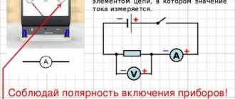
TRAFFIC LEVEL
Sound is mechanical vibrations propagating in an elastic medium (solids, liquids, gases). The ultrasonic frequency range ranges from 20 kHz to 1-2 MHz.
In practice, as a rule, frequencies of 100-400 kHz are used.
The main parameters characterizing ultrasound are:
- speed of spread;
- degree of attenuation (absorption);
- reflection and dispersion coefficients.
They depend on the physical properties of the medium, for example, density, and form the basis of the operating principle of ultrasonic sensors (US).
Structurally, these devices consist of an emitter, a receiver, and a signal processing circuit that analyzes the difference between the emitted and received beams.
Depending on the design and detection principles, several types of ultrasound are distinguished.
Diffuse type.
The time it takes for a signal to travel to an object and back is measured. They are the most common types.
Reflex or reflected beam.
Sensors of this type use an additional reference reflector. This increases the detection accuracy, since it allows you to analyze several parameters of the received beam: reflected from the reflector and the object.
Through beam.
Previous types of ultrasonic sensors have a single-body design. In through-beam detectors, the emitter and receiver are made in separate housings and are installed opposite each other.
They work when the beam intersects, so they can be called linear.
The advantages of ultrasonic sensors include high accuracy, versatility, and the ability to work in conditions of increased pollution.
Rules for installing and working with sensors
Ultrasonic sensors can operate in any position. However, positions that cause severe contamination of the sensor surface should be avoided. Drops of water and various deposits on the surface of the sensor may affect operation, but a small layer of dust or paint will not affect operation. To scan objects with a flat and smooth surface, the sensors should be installed at an angle of 90 ±3°. On the other hand, uneven surfaces can be covered at large angles. In the concept of ultrasonic sensors, a surface is considered rough when the depth of its roughness is greater than or equal to the length of the ultrasonic wave. The sound is then reflected in a diffuse form, resulting in a shorter operating range. In the case of rough surfaces, the maximum permissible angle deviation and the maximum possible determination range must be determined experimentally. Sound-absorbing materials such as cotton wool or soft foam also reduce the operating range. On the other hand, liquid solid materials are very good sound reflectors.
Mounting position and timing. Two or more sensors installed side by side can influence each other. To avoid this, the sensors must be installed at a sufficiently large distance or synchronized with each other. The following table shows the minimum mounting distances between non-synchronized sensors.
Installation distances should be considered as standard values. When objects are placed at an angle, sound may be reflected onto an adjacent sensor. In this case, the minimum installation distances should be determined experimentally.
Some sensors can be synchronized with each other, allowing shorter mounting distances than those shown in the table. If ultrasonic sensors are installed at a distance shorter than those shown in the table, they should be synchronized with each other, which will allow them to take measurements at the same time.
Most microsonic sensors have built-in timing, which is activated by connecting Pin 5 on the connector. Other sensors require an external clock signal.
Sound redirection. The sound wave can be redirected without significant loss using a sound-reflecting, smooth surface. With the help of additional equipment you can deflect the sound by 90°. This can be used in special applications.
Accuracy. Absolute accuracy is the discrepancy between the actual distance between the sensor and the object and the distance measured by the sensor. Accuracy depends on the reflective properties of the object and the physical phenomena affecting the speed of sound in air. Objects with low reflective properties or with surface irregularities exceeding the ultrasonic wavelength have a negative impact on accuracy. It is impossible to determine precisely, but as a rule, an error of several wavelengths of the supersonic frequency used is assumed.
Air temperature. The biggest influence on sound speed and accuracy is air temperature (0.17%/K), which is why most microsonic ultrasonic sensors are temperature compensated. It is even better to take a comparative measurement over a specific distance to determine the effect of temperature. For example, the pico series sensors are specifically designed for such comparative measurements. The accuracy of temperature-compensated sensors reaches ±1%.
Atmosphere pressure. The speed of sound over a wide range does not depend on air pressure. microsonic has developed special sensors for measuring distance under pressure conditions of up to 6 bar.
Relative humidity. Unlike temperature, relative air humidity has virtually no effect on the accuracy of measurements.
Working principle of ultrasonic sensor HC-SR04
The HC-SR04 ultrasonic sensor in our project is used to measure distances in the range of 2-400 cm with an accuracy of 3 mm. The sensor consists of an ultrasonic transmitter, an ultrasonic receiver and a control circuit. The basic principles of operation of an ultrasonic sensor are as follows:
- First, a high-level signal with a duration of 10 μs is generated, which triggers the ultrasonic sensor.
- The module then automatically sends 8 pulses at 40 kHz and then checks whether they are received or not.
- If these emitted signals are received, then the time between the time of transmission of these pulses and their reception is calculated.
The distance can then be calculated using the following formula:
Distance= (Time x Speed of Sound in Air (340 m/s))/2
where Time is the time measured by the sensor; Speed of Sound in Air – speed of sound in air equal to 340 m/s.
Timing diagrams
As already stated, distance measurement is based on echo. First, a pulse of 10 μs duration is transmitted to start the module into operation. After this, the module automatically transmits 8 pulses with a frequency of 40 kHz (that is, ultrasonic frequency) and checks the echo - that is, whether these pulses have returned back, reflected from an obstacle. If the pulses return back, then the distance to the obstacle can be calculated using the following formula:
Distance= (time x speed)/2
In this formula, we divided the product of speed and time by 2 because the measured time is equal to the sum of the times of propagation of the sound wave to the obstacle and back. That is, the time for the sound to reach the obstacle is equal to half the time measured by the sensor.
Timing diagrams of the module operation are shown in the following figure:
Description of Microsonic ultrasonic sensors
Operating principles of ultrasonic sensors.
Ultrasonic sensors emit short, high-frequency sound pulses at a specific interval. They travel through the air at the speed of sound. When it encounters an object, the sound wave is reflected back from it as an echo. The sensor senses this signal and calculates the distance to the object based on the time interval between measuring the signal and receiving the echo of the signal.
Ultrasonic sensors are ideal for suppressing background noise because the distance to an object is determined by measuring the time of flight of the sound wave, not its intensity. Almost all materials that reflect sound can be used as detection objects, regardless of their color. Even transparent materials and thin films pose no problem for ultrasonic sensors. Microsonic ultrasonic sensors can detect targets at distances from 30 mm to 8 m, while producing measurements with very high accuracy. Some sensor models are capable of measuring with an accuracy of up to 0.18 mm. Ultrasonic sensors can see through dusty air, fog, or toner particles. Even a small deposit on the sensor membrane does not affect its operation. The sensor's blind zone is only 20 mm and the emitted flux density is very low, making it possible to use the sensors in completely new applications. The sensors measure the filling level of small bottles on the conveyor and can even detect the presence of thin threads.
General description of ultrasonic sensors with analog and discrete output.
An ultrasonic sensor is a device consisting of an ultrasonic emitter, an electronic part and, on the opposite side, an output connector or cable. The sensor generates an analog signal proportional to the distance to the object or a discrete signal that changes when the object reaches a predetermined distance.
The electronic part contains a piezoelectric element, which emits ultrasound in the generation mode and converts the received vibrations into electric current in the reception mode. The sensor contains control circuits and converters. An electronic circuit measures the time it takes for the ultrasound to pass through the medium and converts it into an analog or digital output signal.
The following types of sensors are distinguished:
- devices operating on the principle of reflecting a signal from an object;
- devices that detect an object, located between the receiver and transmitter.
The measurement accuracy depends on the following factors:
- ambient temperature (in this regard, temperature compensation has been introduced);
- humidity of the air in which ultrasound propagates;
- medium pressure.
Since the main information about the distance to an object is provided by the reflected signal, the characteristics of the surface, along with the angle of incidence of the sound wave, significantly influence the operation of ultrasonic sensors. Sensors work best with highly reflective surfaces: glass, liquids, smooth metal, wood, plastic. For stable operation of the sensor, it is recommended that surfaces with rough relief be located in a position close to perpendicular to the direction of the beam. For smooth surfaces, deviation from the perpendicular direction of the ultrasonic beam is permissible by no more than 3 degrees.
At the location where the sensors are installed, turbulent air flows should be avoided, and the fact of the mutual influence of the sensors when they are located close to each other should be taken into account. Here you can rely on the data in the table given in the “Installation Rules” section.
How does an ultrasonic sensor work in B-mode?
- through an ultrasonic piezoelectric sensor .
- It spreads and is reflected from objects located at different depths. The speed of propagation of ultrasound in tissues is known, so it is possible to determine the distance to the object that reflected this echo signal.
- The amplitude of the received signal is encoded on the screen using shades of gray. The human eye is most sensitive to shades of gray. In this way, the amplitude of the received signal is encoded into brightness on the monitor of the ultrasound scanner.
In this case, the operation of the ultrasonic sensor for the user is as follows:
solid objects look lighter, almost white, while voids, on the contrary, look black.
This occurs because the amplitude of the signal reflected from the bone is large. If you direct the beam into a cavity (emptiness), the ultrasound beam will pass very deep, will be greatly weakened, and the amplitude of the received reflected signal will be close to zero. Biological tissues of greatest interest to the doctor are displayed on the device’s display in intermediate shades of gray.
Features of application
The use of ultrasonic meters has a number of features. For example, to eliminate measurement errors, you must follow the algorithm:
- carry out calibration of the device when the composition of the gaseous medium changes to establish the actual speed of sound;
- carry out calibration at each significant change in temperature, recording the speed values;
- In the future operation of the device when temperature changes occur, do not carry out calibration, but use previously recorded speed indicators.
The process of setting up the sensor is quite labor-intensive. A situation is possible when changes in the gas environment in the tank are not associated with changes in temperature. In this case, you will have to recalibrate the device.
General information
The HC-SR04 ultrasonic sensor uses exactly the same technology as bats (ultrasound). Without going into details, the principle of operation can be described: the sensor sends sound pulses with a frequency of 40 kHz and listens to the echo. Unlike other sensors, the HC-SR04 does not react to sunlight or black objects, but may give false readings from fabric or thin objects. On the front of the HC-SR04 there are two ultrasonic sensors, the first labeled T (Transmiter) is an ultrasonic wave transmitter (TCT40-16T), and the second labeled R (Receive) is a reflected ultrasonic wave receiver (TCT40-16R), according to A 27 MHz output crystal oscillator is located in the center.
On the other side of the HC-SR04 sensor, there is an electrical harness, in which there are three main microcircuits and an electrical harness. To interact with the Arduino controller, a four-pin connector is installed; the assignment of the contacts can be seen below.
Pin assignment: ► VCC: “+” module power ► Trig: trigger input ► Echo: output, echo. ► GND: “-” module power supply
Other Applications
Ultrasonic sensors are used in various fields:
- To control the physical and chemical characteristics of substances. The principle of operation is based on comparing the speed of sound in the substance being tested with the reference one - a discrepancy indicates changes in the substance.
- To control the flow of liquid substances in pipelines. The principle of operation is based on comparing the speed of ultrasonic vibrations in the direction of flow and against it. The method does not require placing the sensor inside the pipeline - the sensor is attached from the outside.
- To determine levels of liquid or bulk materials. The principle of operation is based on the reflection of ultrasound sent by the sensor from the interface between gas and liquid or bulk material. When the level decreases, the time it takes for the oscillations to pass through changes, and the device signals this.
- For the security of premises. There are several operating principles:
- The security sensor emits ultrasonic radiation. When an object appears in the detection zone, the reflected signal is received by the sensor. Then it acts according to the selected algorithm: turns on the siren, sends a signal to the security panel, etc.;
- The signal from the security sensor reaches a receiver located at some distance. When an object passes between the receiver and the emitter, the signal is interrupted, and the sensor operates according to the given algorithm.
For reliability, several ultrasonic security sensors are usually used, operating on different principles.
Fire safety. An ultrasonic fire detector operates on the same principle as a security alarm. It reacts not to an object, but to the movement of air heated by fire. It is highly sensitive. Gas temperature meters and fire alarms based on changes in the speed of propagation when the temperature of the environment changes or the appearance of smoke.
Ultrasonic quality control of materials and products. The principle of operation is based on the difference in the speed of sound in different media and the reflection of ultrasound from the boundary of the media. Detects the exact location of internal defects at a depth of several meters.
Medicine. Carrying out ultrasound examination to diagnose internal pathologies. The principle of operation of the sensor is based on the speed of passage of ultrasonic waves in human tissue. The reflected signal changes wavelength in different tissues of the body. Visualization of the signal on the device screen makes it possible to see the structure of the internal organs of a person.
Ultrasonic sensors. Introduction
A variety of sensors are an integral part of modern active safety systems and will serve as critical components of future systems. Many modern cars are equipped with driver assistance systems and sensors from companies such as Bosch, Denso, Eaton, Hella, Melexis, Mitsubishi, Osram, Valeo and Raytheon. And this list is constantly expanding.
Analysis of the relationship between collisions and driver reaction time shows that many accidents could have been avoided if there had been time to maneuver. A useful role is played by warning signals to the driver or automatic control based on signals from sensors that identify dangerous situations, combined into network connections with a human-machine interface (HMI).
The following main categories of sensors that detect objects are distinguished, depending on their range (range):
- ultra-long range - up to 500 m: IR thermal cameras;
- long range - up to 200 m: 77 GHz radars;
- mid-range - up to 150 m: IR sensors > 300 GHz;
- short range - up to 80 m: video cameras;
- short range - 20 m: 24 GHz radars;
- ultrashort range - up to 4 m: ultrasonic sensors > 20 kHz.
The thermal cameras discussed in the previous article are characterized by a maximum range, but their main purpose is use in night vision systems and monitoring of heated objects. In the daytime, depending on the purpose and vehicle task, radars or lidars, video cameras, and ultrasonic sensors provide optimal results. The element base of video cameras was also discussed in detail in the previous parts of the article, and this publication opens a sequential review of the following active safety technologies based on or including ranking methods: ultrasonic sensors, radars, lidars, 3D cameras, as well as IR night vision systems.
Description and purpose
Ultrasonic liquid level gauge is a device for non-contact automatic remote measurement of the level of liquid media. The main elements of the sensor design are: an ultrasonic emitter and a reflected sound wave receiver.
Emitter
Level meters use the piezoelectric effect - a change in the linear dimensions of a dielectric depending on the frequency of the alternating electric field in which it is placed. In the emitter, the piezoelectric element transmits vibrations to the membrane, which, at a frequency of more than 20,000 hertz, begins to emit ultrasound.
Advantages:
- simplicity of design;
- obtaining ultrasonic vibrations of a significant range;
- compactness.
Flaws:
low radiation power.
Receiver
The piezoelectric effect is reversible: reflected acoustic vibrations hitting the membrane cause the formation of an electric current in the piezoelectric element. Ultrasonic radiation receivers in level gauges operate on this principle: when a reflected signal is received, an electric current is generated in the device circuit.
The use of a piezoelectric circuit made it possible to create a liquid level meter in which the emitter and receiver are a single element. This simplifies and reduces the cost of the device design, installation and maintenance.
Types of ultrasonic liquid level sensors operating on the principle of echolocation:
Level control point alarms
The device is adjusted to two values: minimum liquid level and maximum. If the travel time of the reflected signal corresponds to the minimum specified liquid level, the electronic unit generates a signal in accordance with the specified program. This could be turning on a warning light and sound alarm, commanding the pumps to turn off, etc. The same algorithm is used when the maximum liquid level is reached.
Continuous level monitoring sensors
Meters of this type constantly measure distances to the liquid level. Converts the received data into an analog signal and transmits it in accordance with a given program to its own display, central control panel, etc. Events can be programmed at liquid level limits, as in alarms.
Ultrasonic non-contact sensors are used in industries where the receipt, storage and transportation of liquids, including aggressive ones, are part of the technological process:
- chemical, gas and oil refining industries;
- water supply and water treatment;
- Agriculture;
- metallurgical industry;
- food industry.
Purpose of devices:
- preventing overflow and emptying of liquid containers and the occurrence of related emergencies;
- inclusion in the chain of telemetric control of systems and units as measuring elements;
- monitoring changes in the physical and chemical properties of liquid substances in containers.
Program
Now let's assemble the circuit and write a program to visualize the operation of the sensor. We will measure the distance to the obstacle, count it in centimeters in the program and light the LEDs depending on the distance.
The ultrasonic distance sensor measures quite accurately from 2 centimeters to 4 meters. Therefore, we will turn on one LED per 5 centimeters of distance. If the obstacle is closer than 10 centimeters, a red signal should light up.
Schematic diagram of connecting an ultrasonic distance sensor
Let's write our own function to turn on the LEDs. It will receive the distance from the sensor and turn on the LEDs depending on it.
void LedON(int dist){ digitalWrite(10, dist <= 25); digitalWrite(8, dist <= 20); digitalWrite(7, dist <= 15); digitalWrite(5, dist <= 10); }
As you remember, the digitalWrite() takes two parameters. Pin number and HIGH or LOW value. However, it also allows the use of logical operations. In this case, we used a comparison of a variable with given length values. This will avoid using the if else and save many lines of code.
Another new function pulseIn() . It reads the signal length in microseconds. Accepts 3 parameters. Moreover, the third one is not required.
duration = pulseIn(pin, value, [timeout]);
It works like this. HIGH or LOW signal from the second parameter to appear on the pin set in the first parameter. When the desired signal appears, the microsecond counter starts. And when the signal is gone, the number of microseconds is returned from the function. If the third parameter is set, the function waits for a signal for a certain time. By default, the timeout is 1 second.
Ultrasonic distance sensor hc-sr04
Working principle of ultrasonic position sensor
Ultrasonic sensors are used to calculate the time it may take for sound to travel from a device to an object and back to the sensor (diffusion mode operation), or to check whether a sent signal was received by a specific individual receiver (for opposition mode operation). .
Ultrasonic position sensor
A position sensor is used to monitor the presence or location of various mechanisms, as well as to count the objects present. Such a device can also be used as a limit level indicator for various types of liquids or bulk substances.
There are three main modes of operation of ultrasonic sensors: opposed mode, diffusion mode, and reflex mode.
Opposed mode is characterized by two separate devices, a transmitter and a receiver, that are mounted opposite each other. If the ultrasonic beam is interrupted by an object, the output is activated. This mode is suitable for use in harsh environments where interference resistance is important. The ultrasonic beam travels the signal distance only once. This solution is expensive because it requires the installation of two devices - a transmitter and a receiver.
There are several features
The diffusion mode is provided by the transmitter and receiver located in the same housing. The cost of such installation is much lower, but the response time is longer than with the opposite mode.
The detection range here depends on the angle of incidence on the object and on the properties of the object's surface, since the beam must be reflected from the surface of the object being detected.
For reflex mode, the emitter and receiver are also in the same housing, but the ultrasonic beam is now reflected from the reflector. Objects in the detection range are detected both by measuring changes in the distance traveled by the ultrasonic beam and by estimating absorption or reflection losses in the reflected signal. Sound-absorbing objects, as well as objects with angular surfaces, are easily detected with this mode of operation of the sensor
An important condition is that the position of the reference reflector should not change
Ultrasonic Rangefinder HC-SR04 Arduino
An ultrasonic sensor (also often called a sonar or ultrasonic rangefinder) determines the distance to an object in the same way as bats or dolphins do. The HC-SR04 sensor generates a highly directional signal at a frequency of 40 kHz and catches the reflected signal (echo). Based on the time it takes sound to travel to an object and back, you can quite accurately determine the distance to it.
Many devices for exploring space work on the same principle - echo sounder, sonar, radar, and even police radar for determining the speed of a car. All of these devices emit a highly directional ultrasonic signal and receive a reflected signal back. Unlike infrared rangefinders (IR), the readings of an ultrasonic sensor (sonar) are not affected by the color of the object.
Working principle of ultrasonic rangefinder HC-SR04
But when setting up an ultrasonic sensor on Arduino, difficulties may arise in determining the distance to sound-absorbing objects, since they are capable of completely extinguishing the emitted signal. For ideal distance measurement accuracy, the surface of the object being studied must be flat and smooth. The working principle of the ultrasonic sensor HC-SR04 is shown in the figure above.
Ultrasonic principle
The ultrasonic sensor module consists of a transmitter and a receiver. Any sound above 20 kilohertz (20,000 hertz) is considered ultrasound. For this reason, all sounds above the range of human hearing are called ultrasonic. The transmitter emits 40 kHz ultrasonic waves, but the receiver is designed to only receive 40 kHz sound waves. A receiver sensor located near the transmitter can pick up the reflected sound waves when the module encounters any obstacle ahead.
Whenever there is an obstacle in front of the ultrasonic module, it calculates the time it takes to send signals and receive them, since time and distance are related to sound waves traveling through the air at a speed of 343.2 m/sec. After receiving the signal, the data is displayed on the display. A wide range of materials can be measured this way, including:
- hard or soft;
- colored or transparent;
- flat or curved.
Ultrasonic transmitter and receiver
Most ultrasonic transmitters and receivers are based on the IC 555 timer or complementary metal oxide semiconductor (CMOS) devices. These devices are pre-controlled variable generators. The preset operating frequency may shift due to mechanical vibration or temperature fluctuation. This frequency shift affects the transmission distance of the ultrasonic transducer. The ultrasonic transmitter and receiver circuits described here use the CD4017 ten-year-old counter IC.
Ultrasonic transmitter circuit
The transmitter circuit (Figure 1) is built around two CD4017 decade-old counter ICs (IC1 and IC2), a CD4013 D-type flip-flop IC (IC3), and several discrete components. The device generates stable 40 kHz signals which are transmitted from the TX converter.
Figure 1: Ultrasonic Transmitter Circuit A crystal radio frequency (RF) oscillator built around transistor T 1 (BC549) generates an 8 MHz signal that serves as the input to the first decade counter built around IC1. The decade counter divides the oscillator frequency by 800 kHz. The output of IC1 is fed to a second ten-year counter CD4017 (IC2), which further divides the frequency to 80 kHz. The trigger (IC3) divides the 80 kHz signal by 2 to obtain a 40 kHz signal, which is transmitted by the TX ultrasonic transducer. The L coil is made of 36SWG enameled copper wire which is wound 15 times around an 8mm diameter plastic former used for radio oscillators which has a ferrite bead. The transmitter circuit operates from 9-12 VDC.
Browse products for inventors. Link to the store.
Ultrasonic receiver circuit
The receiver circuit (Figure 2) is built around a decade old CD4017 counter (IC4) and several discrete components. To check the operation of the transmitter, it is necessary to convert the 40 kHz signal to 4 kHz to bring it into the audio range. By using the receiver, the 40 kHz ultrasonic transmitter can be quickly tested. The receiver (RX) unit is located next to the ultrasonic transmitter under test. It detects the 40 kHz transmitted signal, which is amplified by an amplifier built into the BC549 transistor (T2). The amplified signal is fed to decade counter IC4, which divides the frequency by 4 kHz. Transistor T3 (SL100) amplifies the 4 kHz signal to drive the speaker.
Rice. 2: Diagram of the ultrasonic receiver. To power the receiver, use a PP3 9V battery. Place the transmitter and receiver circuits in separate small cabinets. If the 40 kHz converter under test is operating, the receiver circuit makes an audible whistling sound.
electronicsforu.com
Advantages and disadvantages
Advantages of ultrasonic level meters:
- making measurements without direct contact with the liquid medium, which allows you to work with aggressive liquids. The devices are not subject to increased requirements for protection from negative environmental factors;
- the ability to measure the level without penetrating inside the container by placing the sensor outside;
- the price is lower than another type of contactless sensors - radar sensors, due to a simpler design and less expensive components;
- ultrasound reflection occurs from the boundary of liquid and gas, so the measurement accuracy does not depend on the density of the liquid medium, its chemical and physical properties;
- compactness;
- multisensory. The sensor is used to obtain additional information about the state of the liquid and container. Depends on the specific device model.
Disadvantages of liquid level sensors:
- erroneous data due to reflection of ultrasonic signals from structural elements of the container. During the installation stage of the device, it is necessary to prevent structural elements from being located in the frontal plane of the sensor. Ultrasonic sensors are not used in narrow tanks;
- The instrument readings will be erroneous if the gas pressure is greater or less than atmospheric pressure. The device will not work in a vacuum. In such cases, sensors using other physical principles are needed;
- dependence of the accuracy of measurements on the temperature and composition of the gaseous medium, its humidity, contamination, dust content;
- distortion of measurement results due to the formation of foam or turbulent eddies on the surface of the liquid.
Description of HC-SR04
Ultrasonic Distance Sensor - The HC-SR04 module uses acoustic radiation to determine the distance to an object. This non-contact sensor provides high accuracy and stability of measurements. The measurement range is: from 2 cm to 400 cm. The sensor readings are practically not affected by solar radiation and electromagnetic noise. The module is sold complete with a transmitter and receiver.
Specifications of HC-SR04
- Supply voltage: +5V – direct current;
- Quiescent current: < 2 mA;
- Operating current: 15mA;
- Effective working angle: < 15°;
- Measuring distance: 2 cm to 400 cm (1 - 13 inches);
- Resolution: 0.3 cm;
- Measuring angle: 30 degrees;
- Trigger pulse width: 10 microseconds;
- Dimensions: 45 mm x 20 mm x 15 mm.
General view of the HC-SR04 sensor
Pins:
- VCC: +5 volts (DC)
- Trig : Trigger (INPUT)
- Echo: Echo (OUTPUT)
- GND: Ground
Applications and Benefits
Distance sensors are widely used in everyday life. Cars are equipped with parking sensors. In addition to measuring distances, they can simply register the presence of an object within the measuring range, for example in hazardous areas of working machines. Such devices are used in a wide range of industries, for example:
- in the press;
- when converting;
- in robotics;
- during materials processing;
- in transportation, etc.
Distance sensors can be used to monitor or indicate the position of objects and materials. These instruments are so widely used that they can be reliably implemented in applications such as measuring material grain size, determining water levels and much more, since ultrasound reflects from almost any surface. The only exceptions are soft materials, such as wool. Its surface absorbs ultrasonic waves and does not reflect sound.
Gadgets connect to all common types of automation and telemetry tools. Applications range from simple analog connections to complex data networks with multiple sensors.
Operating principle of the sensor
An ultrasonic sensor is a device that uses ultrasonic waves to measure the distance to an object. Ultrasonic sensors, which are tandem microphones and speakers, send and receive ultra-high frequency sound waves to determine the distance to an object or how close it is. Ultra-high frequency sound waves are reflected from an object.
The picture below shows the ultra-high frequency sound waves of an ultrasonic transducer bouncing off the surface of an object.
Features of ultrasonic sensors of the standard mic+ series
| Configuration using buttons The sensor is configured using 2 buttons and an LED display | Configuration from a PC Using the LCA-2 adapter, the sensors are connected via a USB port to a PC | Temperature compensation Built-in temperature compensation ensuring 1% accuracy | Adjustment of output increase/decrease For modification of sensor with analog output |
| Setting the NO/NC output contact To modify a sensor with a discrete output | Measurement filtering 4 types of filtration and 9 degrees of filtration strength | Synchronization When operating up to 10 sensors next to each other | Automatic output switching Automatic switching 4…20 mA / 0…10 V depending on load value |
- Configuration using LinkControl
- Resolution 0.025 mm or 0.18 mm:
for maximum accuracy. - Temperature compensation:
for accurate measurements under temperature changes. - 1 or 2 PNP discrete outputs:
for control. - Analogue output 4…20 mA / 0…10V:
automatic switching between current and voltage output depending on the load. - LED 3-character display:
for viewing current values in mm/cm or %. - 2 buttons and LED display:
for manual sensor settings. - Teach function:
for setting trigger points. - Configurable digital output
: selectable NC or NO contact - Automatic synchronization: for simultaneous operation of up to 10 sensors in confined spaces.
ULTRASONIC LEVEL SENSOR
Among other types of level sensors, ultrasonic ones are distinguished by their ability to operate in continuous monitoring mode.
The principle of operation is to measure the distance to the surface of the liquid (water or fuel). Depending on the type of meter, this value can range from centimeters to several meters.
For example:
- model UM30-15111 operates in the range of 800-8000 mm (80 cm-8 meters);
- and UM30-11113 – 30-350 mm.
Of course, it is impossible to simultaneously ensure the maximum lower and upper measurement limits, that is, most likely you will not find a device that allows you to control distances of 1-2 cm (min) b 10 m (max).
But in practice, such tasks almost never occur. If there is such a need, then you can use two sensors with a range of working distances that overlap each other.
At the same time, they provide high accuracy of level measurement and do not have moving mechanical parts like reed switches (float), which guarantees high reliability, long service life and a minimum amount of maintenance work.
In this case, the measurement error can be no more than 1%.
Depending on the output signal, ultrasounds are:
- analog (depending on the value of the measured value, the current and (or) voltage change at the output;
- digital (transmit information in binary code);
- threshold (have two states: on-off).
All ultrasonic sensors are active devices, meaning they require a supply voltage to operate.
Obviously, it is possible to measure the distance to the interface of media not only to liquid, but also to granular substances.
In addition, the principle of distance measurement is used in other types of sensors, for example parking sensors.
Description and purpose
An ultrasound sensor is a technical device that consists of several main parts:
Emitter
The most common types of emitters are magnetostrictive and piezoelectric.
Magnetostrictive - ultrasonic vibrations occur when the linear dimensions of a ferromagnet change in an alternating magnetic field.
Advantages:
- reliability - at least 10,000 hours of continuous operation;
- efficiency factor 80%.
Flaws:
- complex design;
- water cooling is required.
Piezoelectric - ultrasonic waves arise when the linear dimensions of a dielectric, made in the form of a membrane, change in an alternating electric field.
Advantages:
- simplicity of design;
- obtaining ultrasound of a wide frequency range;
- small sizes.
Flaws:
- low radiation power.
- Ultrasonic sensors mainly use piezoelectric emitters.
Ultrasonic sensor device
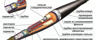
Structurally, the ultrasonic sensor consists of a scanning head, cable and connector.
- The connector is designed to connect the sensor to an ultrasound machine and has many contacts made in the form of pins or metal pads. Quite often, an electronic pre-amplification unit is located in the connector housing; in some cases, the primary amplification unit is located in the scanning head housing.
- The cable is a flexible bundle of many (often several hundred) microconductors connecting the connector and the piezoelectric crystals of the scanning head.
- The scanning head consists of:
1 - acoustic lens designed to form the geometry of the acoustic beam.
The lens is made of special plastic, is in direct contact with the gel and the patient's body, and can be of various colors (often gray, blue or red). 2 - matching layers designed for effective penetration of acoustic waves. They are a combination of different polymer materials.
3 - a matrix of piezocrystals designed to emit ultrasonic waves. This seems possible due to the piezoelectric effect.
The nature of the crystals of piezoelectric elements allows the generation of high-frequency sound under the influence of electrical voltage. Once in the field of high-frequency sound vibrations, the piezoelectric crystal, on the contrary, generates electrical energy. By connecting such crystals to an electrical circuit and processing the signals received from them in a certain way, we can receive an image on the screen of an ultrasound machine.
4 - damper made of solid material , designed to eliminate excessive vibrations in order to shorten the pulse length and increase resolution.
5 — plastic housing with flexible end
6 - coupling - a rubber lining to prevent bending and damage to the cable at the point of exit from the sensor housing.
Watch the video of the structure of the ultrasound sensor, where we not only talked about it, but also showed a cross-section of the sensor!
With such a complex structure, a variety of problems can arise with the sensor: defects in the lens, housing, cable, connector, and even malfunctions of the internal electronics, but thanks to experience and our own developments in this area, we can restore the ultrasound sensor in case of damage of any complexity.
Subscribe to our newsletter, where you will receive interesting articles about ultrasound, ultrasound sensors and other relevant information from the medical field.