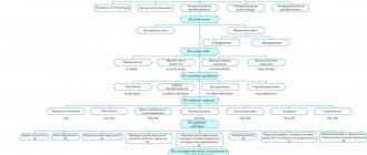
DC motor. Connection diagrams and characteristics of DPT
The DC motor has found wide application in various fields of human activity.
Starting from the use of traction drives used in trams and trolleybuses, ending with the drive of rolling mills and lifting mechanisms, where maintaining high precision of rotation speed is required. The main positive features that distinguish a DPT from an asynchronous motor:
| — flexible starting and adjustment characteristics; |
| — two-zone regulation, which allows you to achieve rotation speeds of more than 3000 rpm. |
Negative features:
| - difficulty in manufacturing and high cost; |
| — during operation, constant maintenance is necessary, since the collector and current-collecting brushes have a short service life. |
A DC motor is used only when the use of an AC motor is impossible or extremely impractical. On average, for every 70 AC motors there is only 1 DC motor.
DPT design
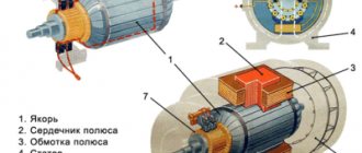
The DC motor consists of:
| — inductor (stator); |
| - armature (rotor); |
| — collector; |
| — current collection brushes; |
| — structural elements. |
The armature and the inductor are separated by an air gap. The inductor is a frame that serves to secure the main and additional poles of the motor’s magnetic system. The main poles have excitation windings, and the additional poles have special windings that help improve switching.
The collector supplies direct current to the working winding, which is placed in the slots of the rotor. The collector has the form of a cylinder and consists of plates isolated from each other; it is mounted on the engine shaft. The brushes are used to remove current from the commutator; they are mounted in brush holders to ensure the correct position and reliable pressure on the surface of the commutator.
Figure 1 – DC motor design
DC motors are classified according to the stator magnetic system:
1) DFC with permanent magnets;
2) DFC with electromagnets:
| — DPT with independent excitation; |
| — DBT with sequential excitation; |
| — DPT with parallel excitation; |
| — DBT with mixed arousal. |
Figure 2 – DC motor connection diagrams
The connection diagram of the stator windings significantly affects the electrical and traction characteristics of the drive.
Starting a DC Motor
The DC motor is started using starting rheostats, which are active resistances connected to the armature circuit. Rheostatic starting is performed for two reasons:
| — if necessary, smooth acceleration of the electric motor; |
| - at the initial moment of time, the starting current Iп = U / Rя is very large, which causes overheating of the armature winding (which has low resistance). |
Only DFCs with a power of up to 1 kW are allowed to start without starting rheostats, the so-called “direct start”.
Figure 3 – Rheostatic engine starting with 3 stages
At the beginning of the start-up, all resistances are connected to the rotor circuit, and as the speed increases, they are removed in steps.
Rotation speed regulation
The rotational speed of a DC motor is expressed by the formula:
This expression is also called the electromechanical characteristic of the DPT, in which:
| U – supply voltage; |
| Iа – current in the armature winding; |
| Rya – anchor chain resistance; |
| k – motor design coefficient; |
| Ф – magnetic flux of the motor. |
Engine torque formula:
Substituting the electromechanical characteristics into the formula, we get:
Thus, based on the above formulas, we conclude that the rotation speed of the DC motor can be adjusted by changing the armature resistance, supply voltage and magnetic flux.
Principle and diagram of operation of a DC motor with parallel excitation
There are several possible types of construction of electric motors operating from a constant voltage source. The principle of their operation is the same, but the differences lie in the features of connecting the field winding (OB) and the armature (I).
The DC electric motor with parallel excitation received its name because its I and OB windings are connected to each other in this way. An electric motor of this type provides the required modes, surpassing products of sequential and mixed types when an almost constant speed of its operation is required.
Three-phase brushless DC motor
This type of motor has excellent characteristics, especially when controlled by position sensors. If the resistive torque varies or is completely unknown, or if it is necessary to achieve a higher starting torque, sensor control is used. If the sensor is not used (usually in fans), the control allows you to do without wired communication.
Features of controlling a three-phase brushless motor without a position sensor:
- the rotor location is determined using a differential ADC (analog-to-digital converter);
- current overload is also determined using an ADC (analog-to-digital converter) or an analog comparator;
- speed adjustment is performed using PWM channels connected to the lower drivers;
- AT90PWM3 and ATmega64 are considered recommended microcontrollers;
- The supported communication interfaces (communication interfaces) are UART, SPI and TWI.
Features of controlling a three-phase brushless motor with a position sensor using the example of a Hall sensor:
- speed adjustment is performed using PWM channels connected to the lower drivers;
- the output of each of the Hall sensors is connected to the corresponding I/O line of the microcontroller, configured to generate interrupts when the state changes;
- supported communication interfaces (communication interfaces) are UART, SPI and TWI;
- current overload is determined using an ADC (analog-to-digital converter) or an analog comparator.
Electric motor device
The main elements that make up a typical three-phase motor are:
- A housing having legs with which it is attached to the foundation;
- A stator whose structure resembles a simple transformer. It has a core and a winding. When current is applied, a vortex electromagnetic field is created.
- Rotor. Main rotating part.
- The shaft on which the rotor is rigidly mounted. The front part extends outward and has a keyway for gears or a pulley. An impeller for cooling and airflow is mounted on the rear part, extending beyond the body.
- Bearings located in the niches of the front and rear covers.
- Sealed terminal box.
Classification of MPT according to the method of powering the inductor and armature windings
Based on this feature, MPTs are divided into 4 types.
With independent excitation
The inductor and armature windings have no electrical connection. In generators of this type, the excitation winding is powered by a direct current network, a battery, or a generator specially designed for this purpose - an exciter. The power of the latter is several hundredths of the power of the main generator.
Scope of application of generators with independent excitation:
- systems of significant power, where the voltage on the excitation winding differs significantly from the generated one;
- systems for regulating the rotation speed of engines powered by generators.
For motors with independent excitation, the armature winding is also energized. Basically these are also high-power units.
The independence of the inductor winding makes it more convenient and economical to regulate the excitation current. Another feature of such motors is the constancy of the excitation magnetic flux under any load on the shaft.
With parallel excitation
The inductor and armature windings are connected in one circuit parallel to each other. Generators of this type are usually used for medium power. In a parallel connection, the voltage generated by the device is applied to the excitation winding. When the inductor and armature windings are connected into one circuit, they speak of a self-excited generator.
In terms of their characteristics, they are identical to motors with independent excitation and have the following features:
- when the load changes, the rotation speed is practically not transformed: the deceleration is no more than 8% when transferring from idle to rated load;
- it is possible to regulate the rotation speed with minimal losses, and within a wide range - 2 times, and for specially designed motors, 6 times.
The inductor of a rotating parallel-wound motor cannot be disconnected from the armature circuit, even if it is already disconnected. This will lead to the induction of a significant EMF in the excitation winding with subsequent failure of the motor. Personnel nearby may be injured.
With sequential excitation
The windings are connected in series to each other. The armature current flows through the field winding. Generators of this type are almost never used, since the process of self-excitation occurs quite rapidly and the device is not able to provide the constant voltage required by most consumers. They are used only in special installations.
Series excitation circuit
Motors of this type are widely used as traction motors (electric locomotives, trolleybuses, cranes, etc.): compared with parallel excitation analogues, when loaded they produce a higher torque with a simultaneous decrease in rotation speed. The starting torque is also high.
Starting the engine with a load below 25% of the rated load, and even more so at idle, is unacceptable: the rotation speed will be too high and the unit will fail.
With parallel-series (mixed) excitation
There are two types of scheme:
- the main winding of the inductor is connected in parallel with the armature winding, the auxiliary winding is connected in series;
- The main winding of the inductor is connected in series with the armature winding, the auxiliary winding is connected in parallel.
Schemes of MPT excitation systems
Connecting a parallel winding before a series winding is called a “short shunt”, and after a series winding - a “long shunt”. Generators of this type are used extremely rarely.
The engines combine the advantages of analogues with parallel and series excitation: they are able to operate at idle speed and at the same time develop significant traction force. But they are almost never used today.
Behavior of an electric motor when loads change
The mechanical characteristic shows the stability of the electric motor over a wide range of load changes, describing the dependence of the torque created by the electric motor on the operating speed of the shaft.
The traction characteristics of the mechanism of this type make it possible to maintain the magnitude of the torque with significant changes in the number of revolutions. Typically, the traction parameters of the unit should ensure a decrease in this parameter by no more than 5%. A simple study demonstrates that the inhibitory parameters turn out to be similar due to the reversibility of the processes. These provisions also apply to the case of mixed excitation.
In other words, such an electric motor is characterized by a rigid characteristic. This nature of work is considered an important advantage of the unit of this type.
Pros - cons
The technical characteristics of asynchronous electric motors with a squirrel-cage rotor are so superior to those of synchronous ones that most drives are made on their basis.
The advantages of such devices are:
- Reliability, simplicity of design, durability;
- No difficulties in repair and maintenance;
- By switching 2 phases, you can make the shaft rotate in the opposite direction;
- Application as a generator.
There are also disadvantages or disadvantages:
- If the phasing is incorrect, the shaft can rotate in the wrong direction and jam other mechanics (gears);
- Inrush current up to five times the rated current;
- Acceleration and braking speed. Some devices with high inertia require higher power motors.
- If a phase is broken, the motor may burn out if the voltage supply is not turned off in a timely manner.
Method for starting two asynchronous motors with squirrel-cage rotors
The invention can be used in mechanisms for general engineering purposes. Starting of engines is carried out by connecting windings in pairs in series before starting, kinematically connecting the rotors of the engines, at least during the start-up, accelerating the engines to a given rotation speed, switching the stator windings to independent power supply. The technical result is that the implementation of the invention makes it possible to increase the reliability of starting and to start two engines without the use of any additional starting devices. 1 salary f-ly, 3 ill.
The invention relates to the field of electrical engineering, in particular, to methods for starting electric motors and can be used in mechanisms for general engineering purposes.
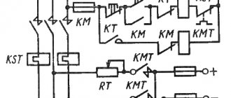
There is a known method of starting asynchronous motors by switching the stator windings from delta to star during start-up (V.A. Venikov, “Transient electromechanical processes in electrical systems.” - M.: “Higher School”, 1970). The disadvantage of this starting method is that that it cannot be used for motors with the main connection according to the “star” circuit. Autotransformer starting of motors is known, in which, during the start of the engine, the voltage on it is reduced using an autotransformer (V. A. Venikov, “Transient electromechanical processes in electrical systems.” - M .: “Higher School”, 1970). The disadvantage of this starting method is the use of an autotransformer, which reduces the reliability and increases the cost of the electric drive. There is a known method for starting a two-motor electric drive (see description of AS USSR N 712921, H 02 P 7/74 , publ. BI N 4, 1980), in which a motor with a wound rotor and a motor with a squirrel cage rotor are started together by connecting starting resistors in the phase rotor circuit for the start time. The disadvantage of this starting method is the use of a motor with a wound rotor, which complicates electric drive and reduces its reliability. The closest to the claimed one is the method of starting groups of asynchronous motors with squirrel-cage rotors (see. description to a.s. USSR N 1396231, H 02 P 1/54, publ. BI N 18, 1988), based on connecting the stator windings to the distribution bus and connecting the windings of two auxiliary motors before starting in pairs and series with each other, after which, upon reaching a given rotation speed, they are disconnected from the distribution bus and transferred to independent power supply. Disadvantage This starting method is that to start a group of motors it is necessary to use two auxiliary motors, which are not used after starting, which reduces the weight and size characteristics and increases the cost of the electric drive. It should also be noted that the process of starting the auxiliary motors themselves does not have stability and predictability of the result, so as due to the unequal mechanical and electrical characteristics of the engines, the run-up time of the rotors to the rated speed is different. This leads to the fact that, as a result of a sharp increase in the electrical resistance of one of the motors as it reaches the nominal operating mode, such a distribution of voltages is possible that the run-up of the other motor will stop. The problem to be solved by the invention is to increase the reliability of start-up, improve the weight and size characteristics of the electric drive. The technical result achieved by implementing the invention is to reduce the load on the supply network at the time of start-up, in conditions of limited power network. This result is achieved by the fact that the stator windings Before starting, the motors are connected in pairs in series, the motor rotors are accelerated to a given rotation speed and the stator windings of the motors are switched to separate power supply, while the motor rotors are kinematically connected to each other at least for the start-up time. The switching moment of the stator windings is determined by the number of engine revolutions. The pairwise series connection is made according to the “common star” or “common triangle” circuit. The method is illustrated by drawings, where in Fig. 1 shows a diagram of the connection of stator windings for starting two asynchronous motors according to the “common star” circuit; in fig. 2 - the same, according to the “common triangle” scheme; in fig. 3 - schematic diagram of an electric drive for starting two motors according to the “common star” circuit. Starting the engines according to the proposed method is carried out in the following sequence: - the stator windings of the two motors are connected in pairs in series according to the “common star” or “common triangle” circuit; — the rated voltage is applied to the input of the resulting connection, while the voltage falling on the stator windings of each electric motor is distributed in proportion to the resistance of their windings; — after a joint run-up, the like-named beginnings and ends of the stator windings of the first motor are connected to each other, and the voltage supplied to the stator windings of the other motor becomes nominal; — disconnect the stator windings of the first motor from the distribution bus; - the stator windings of the first motor are connected, regardless of the previous connection to the main one, according to the “star” or “delta” circuit, the rated voltage is supplied to the engine. During the start-up, the rotors of the started engines are kinematically connected to each other, for example, using a gear drive, a rigid coupling, a chain transfers. After start-up, both the separation of the rotors and independent operation of the motors, as well as the operation of the motors on a common load are possible. The electric drive for implementing the proposed starting method contains two motors 1, 2, the beginnings of the stator windings of which are connected to the distribution bus 3, the first - directly, the second - through a switching element 4, the ends of the stator windings are combined into common points: the first motor - through the switching element 5, and the second - directly, while the ends of the windings of the first motor are connected to the beginnings of the windings of the second motor through the switching element 6. The electric drive operates as follows. To start the motors, turn on switching element 6, after the joint acceleration of the engines, switching element 4 is turned on, motor 1 is excluded from operation, and motor 2 is supplied with rated voltage, then switching element 6 is turned off, and switching element 5 is turned on, as a result, engine 1 is connected to the rated voltage. Thus, as a result of solving the problem, the reliability of the start has increased, and it has become possible to start the engines without using any additional starting devices.
Claim
1. A method of starting two asynchronous motors with squirrel-cage rotors, including connecting the stator windings to the supply network, characterized in that the motor rotors, at least during the start-up, are kinematically connected to each other, the same beginnings and ends of the stator windings are connected in pairs in series according to a common circuit star or common delta, supply the rated voltage to the input of the resulting electrical connection, and after start-up, switch the stator windings to separate power supply.2. The method according to claim 1, characterized in that the switching moment of the stator windings is determined by the engine speed.
DRAWINGS
,
,
Connection to single-phase and three-phase power supplies
According to the type of supply network, AC electric motors are classified into single- and three-phase.
Connecting asynchronous single-phase motors is very easy - to do this, just connect the phase and neutral wires of a single-phase 220V network to the two outputs on the housing. Synchronous motors can also be powered from this type of network, but the connection is a little more complicated - it is necessary to connect the rotor and stator windings so that their single-pole magnetization contacts are located opposite each other.
Connecting to a three-phase network seems a little more complicated
First of all, you should pay attention that the terminal box contains 6 pins - a pair for each of the three windings. Secondly, this makes it possible to use one of two connection methods (“star” and “delta”)
Incorrect connection can damage the motor by melting the stator windings.
The main functional difference between “star” and “triangle” is the different power consumption, which is done to enable the machine to be connected to three-phase networks with different line voltages - 380V or 660V. In the first case, the windings should be connected in a “triangle” pattern, and in the second case, in a “star” pattern. This switching rule allows in both cases to have a voltage of 380V on the windings of each phase.
On the connection panel, the winding terminals are located in such a way that the jumpers used for switching on do not cross each other. If the motor terminal box contains only three terminals, then it is designed to operate on one voltage, which is indicated in the technical documentation, and the windings are interconnected inside the device.
How to prepare for connection
To correctly turn on a three-phase motor, you must remember that there are several winding connection diagrams, including:
The motor windings can be connected to the network in one of two ways - “star” and “delta”. And you should choose the right one based not on convenience or simplicity of design, but on the value of the supply voltage.
For high-power electric motors, it is advisable to use a combined delta-star system. It reduces inrush currents and makes the start smoother.
Diagram of connection of electric motor windings in a triangle
When using a “triangle” circuit, the EM windings are connected in series, connecting ends and beginnings to each other. Their connection points are also connected to the phases. It looks like this:
The main advantage of the “triangle” connection scheme is that an electric motor connected to the network in this way is capable of developing full power. That is, the one indicated in the passport as nominal.
However, the starting currents for the connected electric motor are very high - they exceed the rated current by approximately 7 times. And as a result, the “smoothness” of the machine also suffers. This is very important to take into account when designing the power supply of the device and determining the scope of practical use.
Connection diagram of star motor windings
A star connection involves connecting the ends of the stator windings at one point. Their other ends are connected to the power supply phases. It looks like this:
The star connection guarantees smooth and “soft” operation of the electric motor. In addition, relatively high starting currents are not required to start the machine. But the disadvantage of this connection method is the reduced power of the device.
However, it is important to take into account that electric motors designed for an operating voltage of 220/380 Volt can be connected to a network with a linear voltage of 380 V exclusively using a star circuit.
Combined star-delta motor starting circuit
Both of the above schemes for connecting the windings of asynchronous electric motors have both advantages and disadvantages. Delta allows the machine to reach full power, but requires high inrush current to start. “Star” does not require high starting current and guarantees smooth operation of the device, but does not allow the electric motor to reach its rated power.
To solve this problem, a combined star-delta connection circuit is used. It is used primarily for electric motors with high power (from 5 kW). The combined circuit involves equipping the motor with a special relay, which switches the method of connecting the windings directly during operation.
So, when starting, an electric motor with a combined connection operates according to the “star” scheme. This reduces inrush currents to their rated values. But as soon as the rotor spins up to high speeds, the relay switches the connection circuit to “delta”. This is why the motor can reach its rated power.
When switching, a sharp jump in current is observed. Because of this, the accelerated rotor first loses speed, but then gradually accelerates.
It is worth noting that only electric motors with special markings (Y/Δ) support the combined connection.
Source
Current Applications and Prospects
There are many devices for which increasing uptime is critical. In such equipment, the use of BDKP is always justified, despite their relatively high cost. These can be water and fuel pumps, cooling turbines for air conditioners and engines, etc. Brushless motors are used in many models of electric vehicles
Currently, the automotive industry is seriously paying attention to brushless motors.
BDKPs are ideal for small drives operating in difficult conditions or with high precision: feeders and belt conveyors, industrial robots, positioning systems. There are areas in which brushless motors dominate without alternative: hard drives, pumps, silent fans, small household appliances, CD/DVD drives. The low weight and high power output have also made the BDKP the basis for the production of modern cordless hand tools.
Principle of operation
The operation of the engine is that the controller switches a certain number of stator windings in such a way that the vector of the magnetic fields of the rotor and stator are orthogonal. Using PWM (pulse width modulation), the controller controls the current flowing through the motor and regulates the torque exerted on the rotor. The direction of this acting moment is determined by the mark of the angle between the vectors. Electrical degrees are used in calculations.
In such a situation, the resulting vector shifts and becomes stationary with respect to the rotor flow, which, in turn, creates the necessary torque on the electric motor shaft.
Delta connection
The “triangle” circuit differs from the previous one in that the windings are connected in series. Then the end of the first winding is connected to the beginning of the second, the end of which is connected to the beginning of the third, and the output of which is connected to the beginning of the first.
The advantage of this method is that it ensures maximum power. But when starting the engine, high starting currents are generated, which can lead to the destruction of insulation. Therefore, it is not recommended to apply high voltage.
The delta connection is used to connect a single-phase motor to a single-phase 127 or 220 Volt network. It is also used for three-phase electric motors with two rated voltages when connected to a single-phase network (only to a lower value):
Attention! There are three-phase electrical networks: 600, 380, 220 and 127 Volts. But household ones are classified only with a voltage of 380. And 220 in everyday life refers to single-phase lines. Therefore, the most widespread are 220/380V motors, which can be connected both in the city and in a private home.
From a technical point of view, the delta circuit is also suitable for a high rated voltage. But due to high inrush currents, this is impractical and very dangerous: the insulation will burn out from the heat generated by the winding.
Classification
All three-phase electric motors can be divided into two groups:
Synchronous. They rotate at the speed of a constant magnetic field. To increase power, the rotor is made according to the principle of a transformer - it has windings and a core. Voltage is supplied through carbon brushes to the commutator rings (contacts) mounted on the shaft, and only then to the rotor coils.
Asynchronous, with a squirrel-cage rotor. The rotational impulse comes from the excitation of the stator coils. The short-circuited turns are made in the form of a squirrel wheel. The rotor rotates at a speed lower than the electromagnetic field of the stator. Hence its name.
DC Electric Motor Braking
For braking of electric drives with DPT, there are also three options: counter-braking, dynamic and regenerative. The first occurs due to a change in the polarity of the current in the armature winding and voltage. The second occurs due to the short circuit (through a resistor) of the armature winding. In this case, the electric motor works as a generator, converting the stored mechanical energy into electrical energy, which is released in the form of heat. This braking is accompanied by an instant stop of the engine.
The latter occurs if the electric motor connected to the network rotates at a speed that is higher than the idle speed. The EMF of the motor winding in this case exceeds the value of the voltage I in the network, which leads to a change in the opposite direction of the current in the motor winding, i.e. the engine supplies energy to the network, switching to generator mode. At the same time, a braking torque occurs on the shaft.
Energy conversion principle
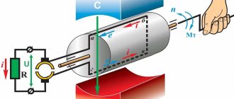
The operating principle of any type of electric motor is to use electromagnetic induction that occurs inside the device after being connected to the network. In order to understand how this induction is created and sets the engine elements in motion, you should turn to a school physics course that explains the behavior of conductors in an electromagnetic field.
So, if we immerse a conductor in the form of a winding, along which electric charges move, into a magnetic field, it will begin to rotate around its axis. This is due to the fact that the charges are under the influence of a mechanical force that changes their position on a plane perpendicular to the magnetic field lines. We can say that the same force acts on the entire conductor.
The diagram below shows a current-carrying loop that is energized and two magnetic poles that give it rotational motion.
The picture is clickable.
It is this pattern of interaction between the magnetic field and the current-carrying circuit with the creation of electromotive force that underlies the functioning of electric motors of all types. To create similar conditions, the device design includes:
- Rotor (winding) is a moving part of the machine, mounted on a core and rotation bearings. It plays the role of a current-conducting rotational circuit.
- The stator is a stationary element that creates a magnetic field that affects the electric charges of the rotor.
- Stator housing. Equipped with mounting sockets with cages for rotor bearings. The rotor is placed inside the stator.
To represent the design of an electric motor, you can create a circuit diagram based on the previous illustration:
After connecting this device to the network, a current begins to flow through the rotor windings, which, under the influence of the magnetic field arising on the stator, gives the rotor rotation, which is transmitted to the rotating shaft. Rotation speed, power and other performance indicators depend on the design of the specific motor and the parameters of the electrical network.
Types of engines and their design
AC electric motors have a different design, thanks to which it is possible to create machines with the same rotor speed relative to the stator magnetic field, and machines where the rotor “lags behind” the rotating field. According to this principle, these motors are divided into corresponding types: synchronous and asynchronous.
Asynchronous
The design of an asynchronous electric motor is based on a couple of important functional parts:
- The stator is a cylindrical block made of steel sheets with grooves for laying conductive windings, the axes of which are located at an angle of 120˚ relative to each other. The poles of the windings go to the terminal box, where they are connected in different ways, depending on the required operating parameters of the electric motor.
- Rotor. In the design of asynchronous electric motors, two types of rotors are used:
- Short-circuited. So called because it is made from several aluminum or copper rods short-circuited using end rings. This design, which is a current-carrying rotor winding, is called a “squirrel cage” in electromechanics.
- Phase. On rotors of this type, a three-phase winding is installed, similar to the stator winding. Most often, the ends of its conductors go to the terminal pad, where they are connected in a star, and the free ends are connected to slip rings. The phase rotor allows you to use brushes to add an additional resistor to the winding circuit, which allows you to change the resistance to reduce inrush currents.
In addition to the described key elements of an asynchronous electric motor, its design also includes a fan for cooling the windings, a terminal box and a shaft that transmits the generated rotation to the working mechanisms of the equipment whose operation is provided by this motor.
The operation of asynchronous electric motors is based on the law of electromagnetic induction, which states that electromotive force can only arise under conditions of a difference in the speed of rotation of the rotor and the magnetic field of the stator. Thus, if these speeds were equal, the EMF could not appear, but the influence on the shaft of such “braking” factors as load and bearing friction always creates conditions sufficient for operation.
Synchronous
The design of synchronous AC electric motors is somewhat different from the design of asynchronous analogues. In these machines, the rotor rotates around its axis at a speed equal to the rotation speed of the stator's magnetic field. The rotor or armature of these devices is also equipped with windings, which are connected at one end to each other and at the other to a rotating collector. The contact pads on the commutator are mounted in such a way that at a certain point in time it is possible to supply power through the graphite brushes to only two opposite contacts.
Operating principle of synchronous electric motors:
- When the magnetic flux in the stator winding interacts with the rotor current, a torque arises.
- The direction of movement of the magnetic flux changes simultaneously with the direction of the alternating current, due to which the rotation of the output shaft is maintained in one direction.
- The desired rotation speed is adjusted by adjusting the input voltage. Most often, in high-speed equipment, such as rotary hammers and vacuum cleaners, this function is performed by a rheostat.
The most common reasons for failure of synchronous electric motors are:
- wear of the graphite brushes or weakening of the pressure spring;
- wear of shaft bearings;
- collector contamination (clean with sandpaper or alcohol).
Three Phase Alternator
Brushless DC motor. General information and device design
Motor controllers of this type are often powered by constant voltage, which is where they get their name. In English technical literature, a valve motor is called PMSM or BLDC.
The brushless motor was created primarily to optimize any DC motor in general. Very high demands were placed on the actuator of such a device (especially the high-speed microdrive with precise positioning).
This, perhaps, led to the use of such specific direct current devices, brushless three-phase motors, also called BLDC motors. In their design, they are almost identical to synchronous AC motors, where the rotation of the magnetic rotor occurs in a conventional laminated stator in the presence of three-phase windings, and the number of revolutions depends on the voltage and load of the stator. Based on certain coordinates of the rotor, different stator windings are switched.
stator windings serve as a fixing element
If one of the windings is turned off, the signal that was induced will be measured and further processed, however, this operating principle is impossible without a signal processing professor. But to reverse or brake such an electric motor, a bridge circuit is not needed - it will be enough to supply control pulses in reverse sequence to the stator windings.
In a VD (switched motor) an inductor in the form of a permanent magnet is located on the rotor, and the armature winding is on the stator. Based on the position of the rotor, the supply voltage for all windings of the electric motor is generated. When a collector is used in such designs, its function will be performed by a semiconductor switch in a switch motor.
The main difference between synchronous and valve motors is the self-synchronization of the latter using the DPR, which determines the proportional rotation speed of the rotor and the field.
Most often, brushless DC motors are used in the following areas:
- freezing or refrigeration equipment (compressors);
- electric drive;
- air heating, air conditioning or ventilation systems.
Stator
This device has a classic design and resembles the same device of an asynchronous machine. The composition includes a core of copper winding (laid around the perimeter in grooves), which determines the number of phases, and a housing. Usually the sine and cosine phases are sufficient for rotation and self-starting, however, the valve motor is often created as a three-phase or even four-phase one.
Electric motors with reverse electromotive force are divided into two types based on the type of winding on the stator winding:
- sinusoidal shape;
- trapezoidal shape.
In the corresponding types of motor, the electric phase current also changes according to the supply method, sinusoidally or trapezoidally.
Rotor
Ferrite magnets are considered the most common and cheapest for making a rotor, but their disadvantage is the low level of magnetic induction, so such materials are now being replaced by devices made from alloys of various rare earth elements, since they can provide a high level of magnetic induction, which, in turn, allows the rotor size to be reduced.
DPR
A rotor position sensor provides feedback. Based on the principle of operation, the device is divided into the following subtypes:
- inductive;
- photoelectric;
- Hall effect sensor.
The latter type has gained the greatest popularity due to its almost absolute inertia-free properties and the ability to get rid of delays in feedback channels based on the rotor position.
Control system
The control system consists of power switches, sometimes also of thyristors or power transistors, including an insulated gate, leading to a current inverter or voltage inverter assembly. The process of controlling these keys is most often implemented by using a microcontroller, which requires a huge number of computational operations to control the motor.
Advantages and disadvantages
The undeniable advantages of such machines include:
- compact dimensions,
- increased starting torque, “versatility”, operation on alternating and direct voltage,
- speed and independence from network frequency,
- soft adjustment of speed over a wide range by varying the supply voltage.
The disadvantage of these engines is considered to be the use of a brush-commutator junction, which causes:
- decreased durability of the mechanism,
- sparking between the commutator and brushes,
- increased noise level,
- a large number of collector elements.
Symbols for DC motors of the P series.
P X1 X2 X3 M P – DC machine; X1 – version according to the degree of protection and cooling method. Without a letter - splash-proof with self-ventilation size 1-6. B – closed version with natural cooling, size 1-4; X2 – dimensions of the electric machine. 1-1 dimensions, 2-2 dimensions, 3-3 dimensions, 4-4 dimensions, 5-5 dimensions, 6-6 dimensions; X3 – nominal length of the armature core. 1 – first length, 2 – second length; M – marine version;
According to the installation method, DC electric motors have a design - IM1001, IM2101, IM2111, IM2131, IM3601, IM3631, IM3611. DC motors can be manufactured with an attached tachogenerator.
Operating conditions for DC electric motors P51, P52.
- DC motors P51, P52 are manufactured for operation at ambient temperatures from -40°C to +40°C.
- At an ambient temperature of 20° ± 5°C% relative humidity 95°±3°C%.
- Withstands vibration, shock, long-term tilting of the axis of a DC electric motor from 45° in any direction and when rolling up to 45° with a rolling period of 7-9 s.
Excitation of a DC motor is serial, parallel, mixed, independent. The heat resistance class of DC electric motor insulation is N. The general level of vibration of electric motors and the level of airborne noise intensity comply with all accepted standards.
Overall and connecting dimensions of DC motors P51, P52, PB51, PB52
| Type of DC motors | Dimensions, mm | Weight, kg for IM2101, IM2102, IM3601, IM2103, IM2104, IM3611, IM3631 | Weight, kg for IM1001, IM1004 | ||||||
| b10 | d1 | d20 | d30 | l10 | l30 | h | |||
| P51U4 | 264 | 35 | 255 | 352 | 225 | 606 | 180 | 122 | 115 |
| PB51U2 | 638 | 127 | 120 | ||||||
| P52U4 | 264 | 35 | 255 | 352 | 265 | 646 | 180 | 142 | 135 |
| PB52U2 | 678 | 147 | 140 |
Main technical characteristics of DC motors P51, P52
| Type | power, kWt | Voltage V | Mains current A | Rotation speed, rpm | Efficiency % |
| P51M | 2,7 | 110 | 33 | 750/1500 | 71 |
| 2,7 | 220 | 17,2 | 750/1500 | 74 | |
| 4,2 | 110 | 52,2 | 1000/2000 | 73 | |
| 4,2 | 220 | 25,6 | 1000/2000 | 74,5 | |
| 7,4 | 110 | 83,6 | 1500/2250 | 79,5 | |
| 7,4 | 220 | 41,8 | 1500/2250 | 80 | |
| 14,5 | 110 | 153 | 3000/3300 | 85 | |
| 14,5 | 220 | 77,3 | 3000/3300 | 85 | |
| P52M | 3,4 | 220 | 20,8 | 750/1500 | 74,5 |
| 5 | 110 | 58,5 | 1000/2000 | 77 | |
| 5 | 220 | 29,2 | 1000/2000 | 77 | |
| 8,8 | 110 | 97,8 | 1500/2250 | 81,5 | |
| 8,8 | 220 | 48 | 1500/2250 | 82,5 | |
| 16 | 220 | 84,5 | 2800 | 86 | |
| 20 | 220 | 104 | 3000/3300 | 87 |
DC electric motors of the P series 1, 2, 3, 4 dimensionsDC electric motors of the P51, P52 seriesDC electric motors of the P61, P62 seriesDC motors of the 2P series (2PO132 - 2PO200, 2PF132 - 2PF200)DC electric motors 2PN, 2PBElectric DC machines of the 4PD series DC motors current DP-112, DK-112, DKU-112MR permanent magnet motors
MTA motors on permanent magnetsPI, PC, 3PI motors on permanent magnetsMX, MVN, MVO motors on permanent magnetsDC electric motors of the DE seriesDC electric motors DPMEDC electric motors DPURDC electric motors PBS, PBSTDC electric motors DK-309M