Mechanical characteristics - electric drive
The mechanical characteristic of the electric drive during dynamic braking has a clearly expressed maximum, determined by the coordinates of the maximum moment Lm and the maximum slip su corresponding to this moment.
The mechanical characteristics of the electric drive are typical for electric drives with subordinate regulation. In the operating load zone of the electric drive, when the AR speed controller operates in the linear section of its static characteristic, the electric drive maintains the given rotation speed. When the electric drive is overloaded, the speed controller is saturated and the stator winding current and motor torque are limited.
The mechanical characteristics of the electric drives for lifting an excavator for one of the positions of the agricultural control device are shown in Fig. 3 - 29 centuries Control systems provide reliable locking of the electric drive and the ability to obtain characteristics of any rigidity, which meets the requirements of various excavator mechanisms.
If the mechanical characteristics of the electric drive do not correspond to the characteristics of the mechanism, the rated power is overestimated, and, consequently, the weights, overall dimensions and cost of the engine increase.
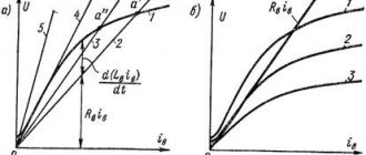
The rigidity of the mechanical characteristics of the electric drive is ensured by the presence of current and voltage feedback. At minimum rotation speed, current feedback is maximum, and as rotation speed increases, it weakens. Since the operation of the drive is subject to increased requirements in terms of rigidity of mechanical characteristics, stabilized power is used in the circuit.
| Graphic definition - .| Mechanical characteristics of the asynchronous motor MTN 312 - 6 when the supply voltage changes (PV 40%. |
Calculations of mechanical characteristics of electric drives and resistor resistances
| Two-current power supply circuits. |
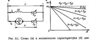
Obtaining the mechanical characteristics of direct and alternating current electric drives with parametric control is achieved by introducing resistances into the circuits of the motor windings. For crane electric drives, circuits using only active resistances have practical application.
| Electric drive load diagram. |
Draw the mechanical characteristic of the electric drive when the full forward reference signal is given, and the static load torque changes from MMAX to - MMAX - Draw the external characteristic En f ( M) in the same quadrants.
Construct a mechanical characteristic of the electric drive when the thrust moment My 2 is Mn, and the no-load speed corresponds to a voltage frequency on the stator of 10 Hz.
It is possible to form almost any mechanical characteristics of an electric drive, up to characteristics similar to a deeply controlled reversible DC electric drive with speed feedback.
| Static characteristics of an asynchronous electric drive. |
The formation of the horizontal section of the mechanical characteristics of the electric drive is carried out in the speed control loop by changing the value of the L / PC signal as a function of the error (that is, the difference in the voltages of the ZI master and the DS speed sensor) in terms of speed. This mode is possible when the speed controller operates in the linear section of its static characteristic, that is, the voltage at its output is less than the voltage set by the BO limiting block.
Characteristics of electric motors
The correct choice of electric motor for a production mechanism is the key to its normal and economical operation. If the electric motor is selected correctly, this will simplify the electric drive control system and possibly reduce the cost of the electric drive. As is known, an electric drive must ensure not only the constancy of steady-state values (speed, torque), but also dynamic ones (transient processes such as acceleration, braking torque, starting torque, etc.).
The main criterion for selecting electric motors is a relationship that displays the value of the torque M of the electric motor and the shaft rotation speed n under the action of this torque. This dependence is called the mechanical characteristic n=f(M). Based on the mechanical characteristics, the electromechanical properties of the engine are analyzed, and the feasibility of using it for various types of mechanisms and devices is assessed. They can be of two types: natural and artificial.
Natural mechanical characteristics: they are removed when the motor is influenced by rated parameters (rated current, winding resistance, voltage, torque, etc.). That is, the engine is connected to the power source without any converting devices - by direct connection.
Artificial mechanical characteristics: they are removed when additional elements are introduced into the motor circuit (additional resistor) or when the supply voltage, frequency (if the motor is of alternating voltage), etc. are reduced. That is, the mechanical characteristics of the engine are artificially influenced.
Mechanical characteristics are also distinguished by changes in shaft rotation speed depending on the increase in torque. They are rated by hardness:
and slope steepness:
To determine the rigidity of a mechanical characteristic, it is necessary to know the change in speed and torque in a given section of the dependence n=f(M). Accordingly, all rigidity calculations are carried out either as a percentage or in relative units.
Mechanical characteristics can also be sorted into groups:
- Absolutely rigid - when the load torque changes, the shaft rotation speed remains unchanged. As an example – the characteristics of a synchronous machine.
- Hard – when the speed decreases slightly as the load torque increases. As an example, independent excitation DC motors DPT NV or the linear part of the characteristics of an asynchronous motor.
- Soft – with increasing load torque, the changes in rotation speed are quite significant. These include series-excited DC motors DPT PV.
Below is a graph of various mechanical characteristics of electric motors:
- – This is an absolutely rigid synchronous machine
- – hard DPT NV
- — soft DPT PV
- – soft DBT of mixed excitation
- – asynchronous motor
The selection of an electric motor is determined by the requirements of production mechanisms. In production such as metal rolling, paper or cardboard production, strict maintenance of constant speed is required, and mechanisms such as lifting and transport do not require strict characteristics (traction electric drives use DPT PV, and it is also used in some crane mechanisms).
Selection of electric motor
The quality of operation of a modern electric drive is largely determined by the correct choice of the electric motor used, which in turn ensures long-term reliable operation of the electric drive and high efficiency of technological and production processes in industry, transport, construction and other areas.
When choosing an electric motor to drive a production mechanism, follow the following recommendations:
- Based on technological requirements, an electric motor is selected according to its technical characteristics (type of current, rated voltage and power, rotational speed, type of mechanical characteristics, duration of operation, overload capacity, starting, regulating and braking properties, etc.), as well as design engine according to the method of installation and fastening.
- Based on economic considerations, the most simple, economical and reliable engine is selected, which does not require high operating costs and has the smallest dimensions, weight and cost.
- Based on the environmental conditions in which the engine will operate, as well as the safety requirements for working in an explosive environment, the design of the engine is selected according to the method of protection.
The correct choice of the type, design and power of the electric motor determines not only the safety, reliability and efficiency of operation and the service life of the engine, but also the technical and economic indicators of the entire electric drive as a whole.
Electromechanical and mechanical characteristics of blood pressure.
Switching diagram and static characteristics of an asynchronous motor.
Asynchronous motors are widely used in industry due to the simplicity of their design, reliability and low cost.
A three-phase IM has a stator winding connected to a three-phase AC network with voltage U
and frequency
f
, and the rotor winding, which can be made in two versions. IM with a wound rotor (making a conventional three-phase winding of conductors with leads to three slip rings). IM with a squirrel-cage rotor - making the winding by pouring aluminum into the rotor slots (Figure 5.1). Single-phase equivalent circuit (Fig. 5.1)
Fig. Connection diagram of the IM with phase (a), squirrel-cage rotor (b), L-shaped single-phase equivalent circuit of the IM.
U1
– effective value of the voltage applied to one phase of the stator winding, frequency
f1
;
Fig Phase and line voltages
Iμ, I1, I'2 – phase currents of the magnetization, stator and rotor windings, respectively (reduced to the number of turns of the stator winding);
R1 – total active resistance of the stator phase;
R'2= R'р + R'2д – total active resistance of the rotor phase, reduced to the number of turns of the stator winding. Includes R'р, – the own resistance of the rotor winding (given); R'2д – additional active resistance (reduced).
x1, x'2 – inductive leakage resistances, respectively, of the phase of the stator winding, rotor winding (reduced to the number of turns of the stator winding);
Rμ – active resistance, taking into account losses in the steel of the magnetic system during magnetization reversal;
xμ – inductive resistance of the magnetization circuit.
When the stator is connected to a three-phase current network, its windings create a magnetic field F
, which rotates at speed
n1
.
E2
in it .
The magnitude of the EMF is proportional to the difference in the speeds of the stator and rotor fields:
E2~( n1- n)Ф
(#)
Along the rotor winding under the influence of EMF E2
currents will flow, creating a magnetic field in the rotor.
The magnetic field of the rotor interacts with the rotating field of the stator, creating a rotating torque. Having started to move, the rotor will “catch up” with the stator field. But an asynchronous motor always has n<n1
.
Otherwise, when equal, EMF E2
, currents, and the magnetic field of the rotor disappear, and braking begins.
The lag of the rotor from the stator magnetic field is called slip:
= (1)
Note that in the equivalent circuit the dependence R'2
from sliding
s
does not correspond to the physical essence of electromagnetic processes.
In fact, the inductive reactance of the rotor X'2 depends on the slip. So, X'2=ω2L2=2πf2L2 (*). At the same time, it is known that the frequency f2
of the EMF
E2
in the rotor winding depends on the slip
f2 = f1 s
. The transformation performed (division by s) made it possible to draw up an equivalent circuit.
Electromechanical and mechanical characteristics of blood pressure.
In contrast to the DPT, the electromechanical characteristic of the IM is presented in the form of a dependence of the rotor current on the slip I'2= f( s)
, and not on the speed ω. The electromechanical characteristic equation follows from the equivalent circuit:
(2)
At the same time, sliding uniquely determines the magnitude of the speed:
From (1) (3)
Therefore, when constructing the characteristics I'2(s), the dependence I'2
(ω).
Fig Electromechanical characteristics
In the graph, the current I1 is greater than the current I'2 in accordance with the equivalent circuit by the value of the no-load current Iμ (Kirchhoff's first law).
Let's consider the characteristic points of the electromechanical characteristics:
1) Ideal idle speed corresponds to the rotor rotation speed ω= ω0
,
slip s=0
(the rotor and stator field rotate synchronously), rotor current
I'2=0
, stator current
I1= Iμ
.
An asynchronous motor cannot provide this mode on its own. To create the mode, it is necessary to rotate it with a frequency ω=ω0
by another motor.
In the equivalent circuit, this mode corresponds to an open rotor circuit ( I'2
).
2) Short circuit (start mode) corresponds to the mode when ω=0
, slip
s=1
, rotor current
I'2= I'2p
, stator current
I1= I1p
.
The current I1p
is called the starting current and reaches 5-7 times the rated current.
, obtained by taking s=1;
3) stator and rotor currents I1, I'2
reach their maximum value at the minimum denominator of expression (2), when =>
This mode occurs at speeds above synchronous ω0
, i.e. in generator mode.
4) At high speeds ω=±∞
, s=
±∞,
the value of the rotor current asymptotically approaches the value
;
Let us obtain an expression for the mechanical characteristics. Power losses in the rotor circuit (sliding losses) are the difference between electromagnetic and useful mechanical power:
Power losses in the rotor, expressed in terms of electrical quantities:
=> , substituting current (2) into expression we get
Rice. Mechanical characteristics of blood pressure
To determine the critical slip sk
and the moment
Mk
we examine the obtained dependence M(s) on the extremum and we will find two points.
(5) (+ in motor, - in generator)
Dividing (4) by (5) and performing transformations, we get a more convenient form:
, where is the Kloss formula
For machines of medium and high power, the active resistance of the stator can be neglected, then a=0 and
(6)
In addition, in the region of small slips, s/sк can be neglected, then
(7)
From (6), designating how one can obtain expressions for finding sk
:
The formula can be used to determine sk
according to catalog data.
Let us analyze the features of the mechanical characteristics of blood pressure. It is non-linear and consists of two parts. The first - the working part - is within the sliding range from 0 to scd. This part of the characteristic is close to linear and has negative stiffness. Here the torque developed by the motor is approximately proportional to the stator and rotor currents. You can use expression (7).
The second part of the mechanical characteristics of blood pressure at s>skd is curvilinear, with a positive stiffness value. Despite the fact that the motor current increases as the slip increases (Figure 5.3), the torque, on the contrary, decreases.
Due to the nonlinearity of the mechanical characteristic, there is a discrepancy between the starting current (5-7 times) and the starting torque (0.4-0.5 rated). Hard start.
Let's look at the startup process.
The start starts with s=1, at the beginning of the start the slip is large. The inductive resistance of the rotor winding X'2=ω2L2=2πf2L2=2 πsf1L2 is large and significantly exceeds R'2. X2′>>R2′.
The EMF is high in this case, since ~Ф(n1-n)
Therefore, the current I'2 is also large, but its active component is small (because cosφ is low). Therefore, the torque developed by the engine is small.
2) When the engine accelerates, the slip decreases, the rotor EMF decreases, and the rotor current frequency f2 and X2′ decrease proportionally.
Accordingly, the total rotor current decreases. Active resistance becomes comparable to inductive resistance, and then becomes larger. Due to the increase in cosφ, the active component of the current increases, and the motor torque also increases.
Those. The uniqueness of the mechanical characteristics of the motor is determined by the dependence of the rotor inductive resistance on slip.
Classification of electric drives
According to the number and communication of executive and working bodies:
- Individual, in which the working executive body is driven by one independent engine, drive.
- Group, in which one engine drives the executive bodies of the PM or several organs of one PM.
- Interconnected, in which two or more EMF or EP are electrically or mechanically interconnected in order to maintain a given ratio or equality of speeds, or loads, or position of the executive bodies of the PM.
- Multi-engine, in which interconnected electric motors and electric motors ensure the operation of a complex mechanism or operation on a common shaft.
- An electric shaft interconnected by an EM, in which, to maintain constant speeds of the PM, which do not have mechanical connections, the electrical connection of two or more EMs is used.
By type of control and control task:
- Automated electronic device controlled by automatic regulation of parameters and quantities.
- A software-controlled electronic device operating through a specialized control computer in accordance with a given program.
- A tracking electronic device that automatically processes the movement of the PM executive body with a given accuracy in accordance with an arbitrarily changing control signal.
- Positional electronic device that automatically regulates the position of the executive body of the PM.
- Adaptive electronic device that automatically selects the structure or parameters of the control device in order to establish the optimal operating mode.
According to the nature of the movement:
- EP with rotational motion.
- Linear electric drive with linear motors.
- A discrete electronic device with an EMF, the moving parts of which are in a state of discrete motion in a steady state.
According to the presence and nature of the transmission device:
- Geared electric drive with gearbox or multiplier.
- Electrohydraulic with hydraulic transfer device.
- Magnetohydrodynamic EP with the conversion of electrical energy into the energy of movement of a conductive fluid.
By type of current:
- Alternating current.
- Direct current.
According to the degree of importance of the operations performed:
- The main EP, which provides the main movement or main operation (in multi-engine EP).
- Auxiliary EP.
- Gear drive.
Drive characteristics
Static characteristics
Static characteristics most often mean electromechanical and mechanical characteristics.
Mechanical characteristics
Mechanical characteristic is the dependence of the angular speed of shaft rotation on the electromagnetic torque M
(or from the moment of resistance
Mc
).
Mechanical characteristics are a very convenient and useful tool for analyzing the static and dynamic modes of an electric drive.
Mechanical and performance characteristics of DC motors
Mechanical characteristics. The mechanical characteristics of engines are usually divided into natural and artificial. The natural characteristic corresponds to the rated supply voltage and the absence of additional resistance in the motor winding circuits. If at least one of the listed conditions is not met, the characteristic is called artificial. The equations for electromechanical ω=f(I i) and mechanical ω=f(M em.) characteristics can be found from the equilibrium equation of EMF and voltages for the motor armature circuit, written on the basis of Kirchhoff’s second law:
where R i is the active resistance of the armature. Transforming (5.35) we obtain the equation of the electromechanical characteristic
In accordance with the armature current I = M em./kF and expression (5.36) is converted into an equation of mechanical characteristics:
This equation can be represented as ω= ω o.id.— Δ ω, where
ω o.id - angular speed of ideal idle speed (at Iа=0 and, accordingly, Mem.=0); Δω= Mem.[(Rя+Rд)/(kФ) 2 ] – decrease in angular speed due to the load on the motor shaft and proportional to the resistance of the armature chain. The family of mechanical characteristics at rated armature voltage and excitation flux and various additional resistances in the armature circuit is shown in Fig. 5.20, a.
Fig.5.20
Source
