Reinforced concrete floor slabs simultaneously serve as enclosing and load-bearing structures of buildings or structures.
Another function that is assigned to these structural elements is to ensure the overall geometric immutability of the spatial frame of the frame.
This is achieved by combining load-bearing vertical elements with a horizontal disk within each floor. To ensure the collaboration of walls, columns or pylons with floor slabs, it is necessary to define hinged or rigid nodes for their connection, which, in turn, depends on the nature of the support of the floors on the walls.
What does the concept mean?
Floors always operate in a building within one floor, taking permanent and temporary loads from their own weight, the mass of floors, equipment, furniture and people using the room.
When external forces are applied, internal forces arise in the element , which determine the geometric section and make it possible to calculate the span structure according to 2 groups of limit states.
At the same time, in the floor slab, along with the loads applied to it, support reactions arise, which are concentrated in places where the elements rest on walls or point vertical structures. These reactions are distributed over the support area and the larger its area, the smaller the load on each cm2 of the vertical element.
Thus, the depth of embedding of the floor in the wall is an important parameter that affects both the value of the supporting transverse force Q in the slab and the axial force N arising in the wall or column. Also, the size of the embedment affects the possibility of local crushing or chipping of the reinforced concrete product during load transfer .
Floor installation
The installation of floors is carried out by a team of four people:
- crane operator who delivers the slab,
- a rigger who rigs slabs,
- two installers involved in coordinating the slab and placing it in a given location.
Supporting floor slabs on a brick wall is one of the most important procedures that requires strict compliance with standards.
Before carrying out installation work, it is imperative to level the ridge of the brickwork. If this is not done, the slab will be unstable. The gaps that appear between the slabs are sealed with cement mortar.
SNiP requirements
The depth of embedding of the floor slab into the wall is standardized based on the requirements of SNiP 2.08.01-85 (“Residential buildings”), as well as SP 335.1325800.2017 (“Large-panel structural systems. Design rules”).
According to the information contained in the reference tables of these documents, developed on the basis of static calculations for 2 groups of limit states, the minimum and maximum required value of floor support is:
- 40 mm when supported on 4 sides. The same condition when supported on 3 sides (if the contact surface runs along both long walls).
- 50 mm – in case of laying the slab on two supports in a span of up to 4200 mm. The same value is required when supporting the floor on 3 sides, if the contact line passes through only one of the two long walls.
- 70 mm – when supported on 2 walls with a span from 4200 to 6000 mm.
- 90 mm – if there are two supports and the floor length is more than 6000 mm.
If we are talking about a monolithic frame of a building, then rigid embedding of horizontal and vertical reinforced concrete elements is achieved when the ceiling is fully supported by the wall. As the contact area between the surface of the wall and the ceiling increases, the uniformly distributed load decreases, which makes it possible to reduce the embedment depth.
Important! As a rule, when installing prefabricated slabs such as PC or PB, builders play it safe and provide a standard embedment size of 120 mm, which is a multiple of ½ the linear size of a standard clay brick.
Features of supporting PC panels
When using PC-type reinforced concrete products as floor slabs, due attention should be paid to calculating the load on the end parts of the panel. The use of additional mesh reinforcement, which takes on a compressive load and is intended to strengthen the end elements of the product, increases its load-bearing capacity, however, the greater the overlap when installing the slab on a load-bearing vertical partition, the less the risk of gradual destruction of the ends of the panel. Due to the presence of end mesh reinforcements, we categorically do not recommend adjusting the size of PC panels yourself (for example, sawing them).
You can add additional rigidity to the structure without the need for a large overlap by filling the voids on one side of the slab. For these purposes, ready-made factory-made liners or self-filling using M200 concrete can be used.
For PC slabs, the issue of overlap of slabs in the plane of increasing pressure from the element located above with increasing area of contact (support) remains relevant. There is a possibility of critical overlap, in which the PC slab can simply collapse due to the extremely high load on the end side. In order to strengthen the vertical surface of the slab, a front mesh is installed in its design.
In addition to this product, the presence of concrete liners is necessary to eliminate empty space on one side of the surface. if they are absent, the cavities must be filled in independently using a concrete solution of a grade not lower than M-200.
Installation methods
There are 3 main ways to support span structures on walls, each of which has both advantages and disadvantages:
- On both sides – the slab operates according to the classical beam scheme, as a bending element, under the influence of permanent and temporary loads. Suitable for installation in any room.
Pros: the design lends itself to elementary calculations, eliminating errors when selecting the type of floor.
Disadvantages: the increased value of support reactions leads to the need to ensure deep embedding of the span element into the wall to increase the contact area. - On three sides. The design is used when it is necessary to create a two-light space in a high room, or when constructing a loggia in the plane of the building facade. There are 2 subtypes of this support:
- Two short and one long sides.
Two long and one short sides.
- On four sides – the slab covers the entire space of the room with a single structure. It is used when special requirements are imposed on the room (for example, to ensure the tightness of the ceiling).
Pros: minimal pressure on the supports eliminates local collapse. It is allowed to reduce the area of contact between the ceiling and the wall.Disadvantages: when the aspect ratio of the slab is a/b or b/a < 2, the structure begins to work as if supported along the contour and requires double calculation in the longitudinal and transverse directions. This leads to an increase in the number of working reinforcement and, accordingly, an increase in the cost of the structure.
Pros: in both cases, the contact area increases compared to support on 2 sides. Accordingly, the pressure from the weight of the slab is reduced by 1 cm2, and the embedment depth can be reduced.
Disadvantages: the overlap ceases to obey a linear relationship when calculated using 2 groups of limit states.
When supported, uneven deflections occur when one long side lies completely on the support, and the second acts as a span structure, deforming under load. If next to such a slab there is a floor element supported on 2 sides, then the difference in deflections can be noticeable to the naked eye.
In practice, prefabricated reinforced concrete slabs supported on 2 sides are most often used, since this design is considered optimal from the point of view of installation and operation under load.
Calculation of the support parameter
Regulates the amount of support of floor slabs on the walls of SNiP (otherwise, a set of norms and rules), which distinguishes the following types of slab sizes:
- modular - the width of the span into which the structure is installed;
- constructive - the actual size of the ceiling slab from one end to the other.
For example, if the modular floor length is 6.0 m, then the actual length is 5.98 m. To obtain a room size of 5.7 m, a slab should be installed with a support of 12 cm. The optimal calculation of the support of the floor slab on the wall is also important for preserving warmth in the room. If the end is too close to the outer surface of the wall, cold air will penetrate inside. This design gives a cold floor in winter.
How is the scheme drawn up?
When preparing a detailed design for a living room or public building, the support scheme for floor slabs depends on both the design, design and functional parameters.
When creating a drawing with the layout of reinforced concrete slabs, the designer takes into account the following factors :
Requirements of regulatory documentation.- Thickness of wall structures. For example, if the thickness of the internal brick wall is 250 mm, the ceiling supported along the contour can only be sealed to a depth of 40 mm.
However, if the design scheme provides for supporting the slabs on both sides of the wall, then the total embedment depth will be 80 mm.As a result, a technological gap of 170 mm will remain at the end of the vertical structure, and 20 - 30 mm is sufficient to form an installation joint. This leads to the designer artificially increasing the embedment depth to avoid the appearance of free space.
- Load-bearing wall material. If the upper rims of masonry are combined with a monolithic reinforced concrete belt, then its homogeneous structure allows it to withstand the requirements of SNiP. When support occurs on a brick or large-block structure, the human factor can affect its local strength, as a result of which the embedment should be performed in excess of standard requirements - up to 120 mm.
- Floor slab span. Here it should be taken into account that when installing an extended slab (6 m or more), the deflection can reach 30–40 mm, due to which the product is deformed and the contact area with the wall may decrease. In this regard, it is necessary to artificially increase the depth of the ceiling.
- Availability of effective thermal insulation. The condition concerns support on the load-bearing part of the outer wall. The floor slab must be located within the warm contour of the building to avoid the formation of cold bridges. Therefore, the support should be provided in such a way that the thermal insulation layer does not become thinner.
- Seismic activity of the area where installation work is carried out - for such floors, an increase in the support area is provided, as well as embedded parts for organizing welds.
The diagram should show the amount of embedding for each element on the floor . If the designer has achieved universality and provided a uniform embedment depth, this fact should be indicated in the notes to the graphic materials.
Supporting unit for a slab on a brick wall
When constructing brick buildings, the masonry is carried out close to the future ceiling, and it is important to leave small niches for installing ceilings. The support unit for the floor slab on the wall is created taking into account the following conditions:
- The ends of the slabs should not rest on the brickwork. For example, with an overlap of 12 cm, the width of the niche should be 13 cm;
- the composition of the mortar for laying and fixing the floors must be identical;
- voids formed in the channels should be filled with concrete liners. They are manufactured at the factory along with the plates.
The minimum support of floor slabs on a brick wall is not standardized if the reinforced concrete product is placed on one side of the end walls. The installation is carried out so that the masonry, which will be higher than the ceiling, does not fall on the formed extreme voids.
Rules for designing interface nodes
When carrying out a detailed design for the installation of floor slabs, in addition to the basic layout of the elements, it is necessary to provide detailing of the nodes , indicating all the nuances when pairing horizontal and vertical elements.
With external walls
The working drawing of the interface between a prefabricated reinforced concrete floor slab and a vertical enclosing structure should show the following details:
- Sectional view of a slab of a given thickness.
- The complete composition of the external wall, including cladding, backfilling and insulation.
- The depth of embedding the structure into the wall.
- Fastening elements to ensure connection (c/p mortar, embedded parts).
- If there is a reinforced concrete belt, a section along this element.
- Scheme of reinforcement of the interface.
- The presence of an elastic insert at the end of the plate.
- Scheme of filling the space between the ceiling and wall cladding.
- If provided for by the project, a diagram of a clean floor with a connection point to the internal part of the vertical enclosing structure.
- When detailing a unit on a typical floor, an image of the overlying external wall.
If the floor slab simultaneously rests on sections of the wall with different designs (for example, at the location of the lintels above window openings), then the assembly must be duplicated for all situations.
With internal carriers
When detailing the support of the slab on internal load-bearing walls, all elements of the drawing are indicated similarly to the algorithm described above. If there are additional design parts, they are also indicated on the unit :
- If the slab is not located in the extreme span, the designer depicts 2 horizontal structures and describes solutions for their connection.
- If the pairing of elements involves twisting or welding, then such parts are also indicated in the project with the designation of the pitch, seam length and other features.
- If there are ventilation ducts located in the thickness of the load-bearing internal wall that affect the installation diagram, such sections are drawn out in a separate drawing.
All additional consumables included in the project are also displayed in the specification for the drawing, indicating their brands and quantities.
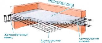
Features of installation of floors for buildings made of aerated concrete
The slab ceiling is supported on the wall by a circular reinforced belt, which is mounted along its perimeter. Such a monolithic concrete strip covering the entire building is required if the support value is less than 12 cm. The following parameters for the reinforced belt are recommended:
- thickness 12 cm;
- width 25 cm;
- the support depth is the same as for reinforced concrete floors.
In combination with strong reinforced concrete slabs, the reinforced belt creates a rigid structure that provides sufficient resistance to the structure of emergency impacts, temperature changes and shrinkage deformations.
If the amount of support of the ceiling on the wall is more than 12 cm, then the building does not need an additional reinforced belt. In such cases, it is enough to construct a reinforced belt from a ring anchor along the outer perimeter of the slabs.
Installation technology
When installing prefabricated concrete floor slabs on a construction site, a typical interface is performed according to the following algorithm :
- The laying of load-bearing walls is completed 2 - 3 rows before the design floor height.
- A reinforced monolithic belt is arranged along the support lines of the slabs, allowing the support reactions from the floor to be evenly distributed throughout the entire volume of the masonry. In some cases, the project does not provide for such a structure, and the installation of span structures is carried out over an underlying layer of rigid c/p mixture.
- An underlying layer is applied on top of the belt, smoothed over the entire intended area of support for the slab.
- A sling bracket or chains are attached to the ceiling element through mounting loops.
- The lifting mechanism lifts the slab to the desired level, and the installers carefully bring it to the support area.
- A truck or tower crane slowly lowers the slab onto the support platform under the control of the installers.
- If there is a slight deviation in the position of the structure, workers correct the element with crowbars or a sledgehammer through a wooden block.
- The following floor elements are laid using a similar principle.
- When the installation of prefabricated concrete products is completed, workers caulk the seams with a rigid cement-sand mixture.
- Reinforcing anchors are installed in the mounting loops of the slabs, which are subsequently intersected “crosswise”.
- The anchors are welded together, and the hinges are pressed to a horizontal surface with sledgehammers.
Upon completion of the installation work, the installation of monolithic sections begins, if the layout of the slabs provides for such a design solution.
Support unit design
When constructing a brick building with floors made of flat concrete elements, masonry in the full thickness of the fence is carried out to the design level of the bottom of the ceiling. Then the brick is placed only from the outer part so that a niche is formed where the slab will lie. The process is accompanied by the following:
- If the depth of support is 12 cm (exactly half a brick), then the niche is made at least 13 cm wide so that the end part of the slab does not rest against the brickwork.
- Before installing the ceiling, a layer of cement-sand mortar of the same grade that was used during the construction of the masonry is laid on the base.
- Since the edge zones of the slabs will absorb part of the load from the wall erected above, the voids at the end are tightly sealed with concrete liners so that the product does not collapse from compression.
As a rule, manufacturers of reinforced concrete products provide concrete liners at the factory. If this has not been done, the voids must be filled with M200 concrete mixture under construction site conditions.
In the end walls of the building, the floor slabs rest on the external fences not only with their ends, but also with one side part. Here the depth of support is not standardized, but for reliability, this unit should be designed in such a way that the load from the brickwork does not fall on the first void of the product. Otherwise, squeezing the hollow part may cause its destruction. The support arm should be minimal; its size depends on the design of the slab.
Errors during the work process
Calculation of the area for supporting the floor slab on the walls is a responsible process, the correct execution of which determines the safety of the operation of the future structure.
If the designer makes mistakes, deviates from regulatory requirements, or omits important details when performing interfaces, serious consequences may occur :
- If the embedding is not deep enough, local crushing of the masonry may occur, which is fraught with the loss of geometric immutability of the entire structure with subsequent collapse.
- When deep embedding, zones of freezing of the structure and condensation from the dew point in the room may form.
- When walking through ventilation ducts, partial trimming of the end of the slab may be necessary.
- If the actually erected walls have a slight deviation from the vertical axis, and the designer did not provide for a margin when calculating the support, the entire floor structure will no longer meet the requirements of SNiP.
Thus, when calculating the support of the floor slab on the walls, all the features of the installation of the structure should be taken into account - from the values recommended by regulatory documents to the human factor and possible deviations of the structure from the design dimensions.
Parameters for support amount
The maximum and minimum support of the slab floor on the wall is determined by the following factors:
- The purpose of the building is residential, industrial, administrative.
- The material from which the load-bearing walls are made and their thickness.
- The size of the overlapped span between the walls.
- The size of the reinforced concrete floor slab and its weight.
- Future loads on floors.
- Seismic indicators of the building location.
In accordance with SNiP data, the support of floor slabs on walls is from 9 to 12 cm, depending on the factors described above. The final size is determined by engineers when designing the building. It is important to correctly calculate the amount of overlap, otherwise the pressure of the ceilings can lead to gradual cracking and destruction of the building.
Minimum size for supporting a floor slab on a brick wall
What should be the minimum support for a floor slab on a brick wall to ensure the reliability and durability of the structure? This is a serious issue; the stability of the building to loads and the safety of the people in it depend on its solution. That is why the depth of laying flat reinforced concrete products on brickwork is regulated by construction regulations (SNiP).
The strength of the entire house structure depends on the quality of installation of floor slabs.
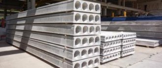
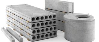
About hollow reinforced concrete products
It is difficult to understand the issue if you do not know what floor slabs are. These are structural elements of permanent buildings, made of reinforced concrete, for the installation of floors between floors. Inside along the entire slab there are voids of various shapes, most often round.
Products are manufactured according to standard designs - a series of drawings that indicate design features and dimensions. The length of the elements is 1.5-12 m. Modern production technologies make it possible to cut slabs of the required length in increments of 100 mm. The width of the product is made into 4 types: 1000, 1200, 1500 and 1800 mm.
The standard distributed load for which each element is designed is 800 kg/m2. The slab can have a thickness of 16-33 cm depending on the design and length, the most common size is 22 cm.
Floor slabs are practically irreplaceable products. An alternative is a floor made of wooden beams or monolithic reinforced concrete. Wood is inferior to reinforced concrete in terms of load-bearing capacity, and the construction of a monolithic structure is a complex and expensive process.
What determines the minimum distance for support?
Regulatory documents establish the minimum length for supporting the end part of a hollow-core slab on a wall made of brick - 9 cm. Such a decision is made by design engineers with justification and calculations. Factors influencing the depth of overlap:
The parameters for supporting the slab depend on the type of future structure.
- overall size of the span and length of the reinforced concrete product;
- the magnitude of the distributed and point load on the concrete floor;
- types of loads - static, dynamic;
- thickness of load-bearing brick wall;
- type of building - residential, administrative or industrial.
All of these factors must be taken into account when calculating the reliability of the structure. In accordance with the standards, the end of the reinforced concrete hollow slab is placed on the wall so that the overlap size is 9-12 cm, the exact data is obtained by calculation.
If you study the series by which floor elements are produced, they indicate 2 types of sizes:
Table for calculating the cross-section of floor beams.
- Modular. This is the theoretical width of the span where the element should be placed.
- Constructive. This is the clear length of the ceiling tile from one end to the other.
For example, a concrete product with a modular length of 6 m has a real dimension of 5.98 m, which must be taken into account when designing. To get a clear room width of 5.7 m, you need to lay the slab on a brick wall to a depth of 120 mm; for finishing with plaster, 20 mm will remain on each side; there is also a brick ceiling.
The question arises - why is the size of the support so small, because the slab can be laid at 20-30 cm, as long as the width of the fence allows it. But this will not be support, but pinching of the reinforced concrete element, since its end also bears part of the load from the wall built above. In such a situation, both the slab and the load-bearing partition will not work properly, which will lead to the slow destruction and cracking of the brickwork.
Conversely, due to too little overlap, the heavy slab, along with the entire load, will begin to act on the edge of the masonry and eventually collapse it.
Therefore, the minimum support of 9 cm is rarely used in practice; usually 10-12 cm is accepted.
There is another reason why the edge of the ceiling should not be too deep inside the enclosing structure. The closer the end of the slab is to the outer surface, the more heat is lost in such a structural unit, because concrete conducts heat well. The result will be a bridge of cold, which will cause cold floors in the house.
Support unit design
When constructing a brick building with floors made of flat concrete elements, masonry in the full thickness of the fence is carried out to the design level of the bottom of the ceiling. Then the brick is placed only from the outer part so that a niche is formed where the slab will lie. The process is accompanied by the following:
- If the depth of support is 12 cm (exactly half a brick), then the niche is made at least 13 cm wide so that the end part of the slab does not rest against the brickwork.
- Before installing the ceiling, a layer of cement-sand mortar of the same grade that was used during the construction of the masonry is laid on the base.
- Since the edge zones of the slabs will absorb part of the load from the wall erected above, the voids at the end are tightly sealed with concrete liners so that the product does not collapse from compression.
As a rule, manufacturers of reinforced concrete products provide concrete liners at the factory. If this has not been done, the voids must be filled with M200 concrete mixture under construction site conditions.
In the end walls of the building, the floor slabs rest on the external fences not only with their ends, but also with one side part. Here the depth of support is not standardized, but for reliability, this unit should be designed in such a way that the load from the brickwork does not fall on the first void of the product. Otherwise, squeezing the hollow part may cause its destruction. The support arm should be minimal; its size depends on the design of the slab.
Features of these systems
In order for the ceiling to hold tightly and be able to withstand large and even excessive loads, it is necessary to correctly calculate the node for supporting the floor slab on the brick wall. Depending on how it is implemented, it will be possible to place a certain load on a given floor of the building. By the way, please note: a slab support unit cannot be constructed based on lintels rather than load-bearing walls.
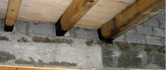
Scheme of embedding a wooden floor beam into a brick wall: 1 – wooden beam; 2 – the end of the beam, coated with resin and wrapped in roofing felt; 3 – waterproofing; 4 – brick wall; 5 – air gap between the wall and the beveled end of the beam.
In construction, as in any industry, there are special regulatory documents governing the standards for installing support units on various walls, including brick ones.
Sealing seams between floors
After the optimal size for supporting the floor slabs on the walls has been determined, and the reinforced concrete structures themselves have been installed, the seams between them should be sealed.
For this, a sand-cement mortar is used if the gaps are small. If there are large gaps, use the following methods:
- The formwork is constructed from wooden boards, into which the mortar is then poured.
- Large gaps can be sealed with fragments of reinforcement, fragments of bricks and other materials. They are compacted into the cracks, which are then covered with concrete mortar.
It is important to seal the voids formed when installing slabs immediately. This greatly simplifies the finishing work that will be carried out upon completion of construction.
The future strength and durability of the structure depends on the correct calculation of the amount of support of the ceiling on the wall. Therefore, this process is regulated by SNiP rules and is carried out by experienced designers.