Technical specifications
The operation of the generator is determined by the relationship between the basic quantities, which are its main characteristics:
- relationships between quantities at idle;
- external parameters;
- adjustment values.
The external characteristic of a DC generator is extremely important, as it reveals the relationship between voltage and load. It is shown on the graph. According to the latter, a slight decrease in voltage is observed, but it is almost independent of the load current (if the engine speed is maintained).
External characteristics of the GPT
In devices with parallel excitation, the influence of the load on the voltage is more pronounced. This is explained by a decrease in current in the windings. The higher the load current, the faster the voltage at the terminals of the unit will decrease.
Properties of parallel-excited GST
If you increase the current value during sequential excitation, the EMF will increase. But the voltage will not reach a high electromotive force value, since part of the energy will go to losses from eddy currents.
Properties of GST with sequential excitation
When the voltage reaches its maximum value and the load simultaneously increases, the former begins to rapidly decrease while the electromotive force curve continues to rise. This is considered a major drawback that limits the use of this type of generator.
In devices with mixed excitation, counter-connections of both coils are provided. The final force with a unidirectional connection is equal to the sum of the vectors of magnetizing forces, with a counter-directional connection - their difference.
You may be interested in Features of 4x18 ballast
With a uniform increase in load, the voltage at the terminals remains almost unchanged. It will increase only if the number of wires in the series winding exceeds the number of turns that corresponds to the nominal excitation of the armature.
Properties of GST with mixed excitation
Generators with counter-connection are used if it is necessary to limit short-circuit currents. For example, when connecting welding machines.
Efficiency
An important characteristic of a generator is its efficiency - the ratio of useful and total power: η = P 2 / P1. At idle, this ratio is zero (η=0)
At rated loads, the efficiency will reach its maximum value. Powerful units have an efficiency of about 90%.
Efficiency
EMF
The electromotive force (its value) is proportional to the magnetic flux, the number of conductors (active) in the windings, and the frequency of rotation of the armature. If you change the last parameters, you can easily control the EMF value. The latter also applies to tension. The desired result is achieved by changing the armature rotation frequency.
Power
The useful and full power of the device is allocated. At a constant electromotive force, the total power is directly proportional to the current: P=EIa. Useful, which is given to the circuit, P1 = UI.
Anchor reaction
If an external load is connected to the alternator, the electric currents in its winding will create a magnetic field. Then resistance of the armature and stator fields will arise. The field will be strongest in those places where the rotor approaches the magnetic poles, and very weak at the points of maximum distance. The rotor senses the magnetic saturation of the steel coil cores. The strength of the reaction directly depends on the saturation in the wires. As a result, sparking of the brushes will occur on the collector plates.
Rotor reaction
Reducing the reaction is achieved by using replenishing magnetic poles or moving the brushes away from the axis line.
Classification
There are two types of DC generators:
- with independent excitation of windings;
- with self-excitation.
To self-excite generators, they use electricity generated by the device itself. Based on the principle of connecting the armature windings, self-excited alternators are divided into types:
- devices with parallel excitation;
- alternators with series excitation;
- mixed type devices (composite generators).
Let us consider in more detail the features of each type of connection of armature windings.
With parallel excitation
To ensure normal operation of electrical appliances, a stable voltage is required at the generator terminals, independent of changes in the total load. The problem is solved by adjusting the excitation parameters. In alternators with parallel excitation, the coil leads are connected through a control rheostat in parallel to the armature winding.
Excitation rheostats can short-circuit the winding to themselves. If this is not done, then when the excitation circuit breaks, the self-induction EMF in the winding will sharply increase, which can break through the insulation. In a short circuit condition, energy is dissipated as heat, preventing destruction of the generator.
Electric machines with parallel excitation do not require an external power source. Due to the presence of residual magnetism, which is always present in the core of the electromagnet, self-excitation of parallel windings occurs. To increase residual magnetism in field coils, electromagnet cores are made of cast steel.
The self-excitation process continues until the current reaches its maximum value and the EMF reaches its nominal values at optimal rotation speed of the armature.
Advantage: generators with parallel excitation are weakly affected by short-circuit currents.
With independent excitation
Batteries or other external devices are often used as a power source for field windings. Models of low-power machines use permanent magnets, which ensure the presence of the main magnetic flux.
On the shaft of powerful generators there is an exciter generator that produces direct current to excite the main armature windings. For excitation, 1–3% of the rated armature current is sufficient and does not depend on it. The EMF is changed by a control rheostat.
The advantage of independent excitation is that the excitation current is not affected in any way by the terminal voltage. And this ensures good external characteristics of the alternator.
With sequential excitation
The series windings produce a current equal to the generator current. Since the load is zero at idle, the excitation is zero. This means that the idle speed characteristic cannot be removed, that is, there are no adjustment characteristics.
In generators with series excitation there is practically no current when the rotor rotates at idle speed. To start the excitation process, it is necessary to connect an external load to the generator terminals. This pronounced dependence of voltage on load is a disadvantage of series windings. Such devices can only be used to power electrical appliances with a constant load.
With mixed excitement
Useful characteristics combine the designs of generators with mixed excitation. Their features: the devices have two coils - the main one, connected in parallel to the armature windings, and the auxiliary one, which is connected in series. A rheostat is included in the parallel winding circuit, which is used to regulate the excitation current.
Read also: Test drive Chevrolet tracker video
The process of self-excitation of an alternator with mixed excitation is similar to that of a generator with parallel windings (due to the absence of an initial current, the series winding does not participate in self-excitation). The no-load characteristic is the same as that of an alternator with parallel winding. This allows you to regulate the voltage at the generator terminals.
Mixed excitation smoothes out voltage ripple at rated load. This is the main advantage of such alternators over other types of generators. The disadvantage is the complexity of the design, which leads to an increase in the cost of these devices. Such generators do not tolerate short circuits.
How do machines operating on direct current work?
DC electric machines are reversible devices, that is, with a certain connection they can be used either as a motor or as a current generator.
Generator in section
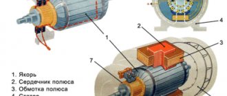
Design of DC machines
- The collector is a metal sliding contact through which the rotor is connected to external electrical circuits;
- Brushes (usually graphite or copper-graphite) are the mating part of the sliding contact, which constantly rubs against the commutator as the rotor rotates;
Switching in DC machines
- The rotor (armature) is the moving part of the unit. When it rotates, the process of electromagnetic induction starts.
- Main poles;
- Excitation coil;
- Bed – unit body;
- A side cover that covers the cooling impeller and holds the rolling bearings on which the rotor rotates;
- Fan - designed to cool the machine while it is running.
Design and principle of operation of DC machines - stator
The main working parts of DC machines are the rotor, which is more often called an armature, and the stator. This part of the structure is called internal electrical.
There is also an external electrical part, with the help of which the engine is controlled, and external electrical networks are also connected.
The design of a DC machine - the armature is located on the shaft
The remaining elements relate to the mechanical part.
- The frame of a DC machine is made of durable metal - usually structural steel.
- The main and additional stator poles are attached to the inside of the frame. The cores of the main poles are made of steel plates. For additional poles they go mostly massive.
- The excitation winding is located at the main poles - their MMFs form the working flow. The windings of the additional poles ensure normal switching.
Current switching in DC machines
The rotor magnetic circuit is made of special electromagnetic steel.
The anchor itself has the following structure:
Figure 5. Diagram of an electric motor with a multi-winding armature
The design and principle of operation of a direct current generator on video
Operating principle of a DC generator
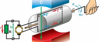
The operation of the generator is based on the use of the law of electromagnetic induction, according to which an emf is induced in a conductor moving in a magnetic field and crossing a magnetic flux.
One of the main parts of a DC machine is a magnetic circuit through which the magnetic flux is closed. The magnetic circuit of a direct current machine (Fig. 1) consists of a stationary part - stator 1 and a rotating part - rotor 4. The stator is a steel body to which other parts of the machine are attached, including magnetic poles 2. An excitation winding is mounted on the magnetic poles 3, powered by direct current and creating the main magnetic flux Ф0.
Rice. 1. Magnetic circuit of a DC machine with four poles
Rice. 2. Sheets from which the rotor magnetic circuit is assembled: a - with open grooves, b - with semi-closed grooves
The rotor of the machine is made of stamped steel sheets with grooves around the circumference and with holes for the shaft and ventilation (Fig. 2). The working winding of the DC machine is placed in the grooves (5 in Fig. 1) of the rotor, i.e., the winding in which e is induced by the main magnetic flux. d.s. This winding is called the armature winding (which is why the rotor of a DC machine is usually called an armature).
The meaning of e. d.s. The DC generator may change, but its polarity remains constant. The operating principle of a DC generator is shown in Fig. 3.
The poles of a permanent magnet create magnetic flux. Let us imagine that the armature winding consists of one turn, the ends of which are connected to various semirings, isolated from each other. These half rings form a commutator that rotates with the armature winding. At the same time, stationary brushes slide along the commutator.
When a coil rotates in a magnetic field, an e is induced in it. d.s
where B is magnetic induction, l is the length of the conductor, v is its linear speed.
When the plane of the coil coincides with the plane of the center line of the poles (the coil is located vertically), the conductors cross the maximum magnetic flux and the maximum value of e is induced in them. d.s. When the coil takes a horizontal position, e. d.s. in conductors is zero.
Direction e. d.s. in the conductor is determined by the right-hand rule (in Fig. 3 it is shown by arrows). When, during the rotation of the turn, the conductor passes under the other pole, the direction of e. d.s. it changes to the opposite. But since the commutator rotates along with the coil, and the brushes are motionless, the conductor located under the north pole is always connected to the upper brush, e.g. d.s. which is directed away from the brush. As a result, the polarity of the brushes remains unchanged, and therefore remains unchanged in the direction of e. d.s. on the brushes - still (Fig. 4).
Rice. 3. The simplest DC generator
Rice. 4. Change in emf over time. the simplest DC generator
Although e. d.s. The simplest direct current generator is constant in direction, but it changes in value, taking two times the maximum and two times zero values for one revolution of the turn. E.m.f. with such a large ripple is unsuitable for most DC receivers and in the strict sense of the word it cannot be called constant.
To reduce ripple, the armature winding of a DC generator is made of a large number of turns (coils), and the collector is made of a large number of collector plates, isolated from each other.
Let us consider the process of smoothing pulsations using the example of the winding of a ring armature (Fig. 5), consisting of four coils (1, 2, 3, 4), two turns each. The armature rotates clockwise with a frequency n and e is induced in the armature winding conductors located on the outer side of the armature. d.s. (direction shown by arrows).
Read also: Do-it-yourself dry cleaning of car seats
The armature winding is a closed circuit consisting of turns connected in series. But relative to the brushes, the armature winding consists of two parallel branches. In Fig. 5, and one parallel branch consists of coil 2, the second - of coil 4 (in coils 1 and 3 the emf is not induced, and they are connected at both ends to one brush). In Fig. 5, b the anchor is shown in the position it occupies after 1/8 of a turn. In this position, one parallel branch of the armature winding consists of series-connected coils 1 and 2, and the second - of series-connected coils 3 and 4.
Rice. 5. Scheme of the simplest DC generator with a ring armature
Each coil, when the armature rotates in relation to the brushes, has a constant polarity. Change e. d.s. coils in time when the armature rotates is shown in Fig. 6, a. E.m.f. on the brushes is equal to e. d.s. each parallel branch of the armature winding. From Fig. 5 it is clear that e. d.s. parallel branch is equal to or e. d.s. one coil, or the sum of e. d.s. two adjacent coils:
As a result of this pulsation e. d.s. armature windings are noticeably reduced (Fig. 6, b). By increasing the number of turns and collector plates, an almost constant e.g. can be obtained. d.s. armature windings.
Design of DC generators
In the process of technical progress in electrical engineering, the design of DC machines changes, although the main parts remain the same.
Let's consider the design of one of the types of direct current machines produced by industry. As stated, the main parts of the machine are the stator and the armature. Stator 6 (Fig. 7), made in the form of a steel cylinder, serves both for fastening other parts and for protection from mechanical damage and is a stationary part of the magnetic circuit.
Magnetic poles 4 are attached to the stator, which can be permanent magnets (for low-power machines) or electromagnets. In the latter case, an excitation winding 5 is mounted on the poles, powered by direct current and creating a magnetic flux stationary relative to the stator.
With a large number of poles, their windings are connected in parallel or in series, but so that the north and south poles alternate (see Fig. 1). Between the main poles there are additional poles with their own windings. Bearing shields 7 are attached to the stator (Fig. 7).
Armature 3 of a DC machine is made of sheet steel (see Fig. 2) to reduce power losses and eddy currents. The sheets are isolated from each other. The armature is a moving (rotating) part of the machine's magnetic circuit. The armature winding, or working winding 9, is placed in the armature slots.
Rice. 6. Change in time of the emf of the coils and winding of the ring armature
Currently, machines with an armature and drum-type winding are produced. The previously discussed winding of the ring armature has the disadvantage that e. d.s. is induced only in conductors located on the outer surface of the armature. Consequently, only half of the conductors are active. In the winding of the drum armature, all conductors are active, i.e., to create the same e. d. with, as in a machine with a ring armature, almost half as much conductor material is required.
The armature winding conductors located in the grooves are connected to each other by the frontal parts of the turns. Each slot usually contains several conductors. The conductors of one slot are connected to the conductors of another slot to form a series connection called a coil or section. The sections are connected in series and form a closed circuit. The connection sequence must be such that e. d.s. in conductors included in one parallel branch had the same direction.
In Fig. Figure 8 shows the simplest drum-type armature winding of a two-pole machine. Solid lines show the connection of sections to each other from the collector side, and dotted lines show the frontal connections of conductors from the opposite side. From the connection points of the sections, taps are made to the collector plates. Direction e. d.s. in the winding conductors is shown in the figure: “+” - direction from the reader, “•” - direction towards the reader.
The winding of such an armature also has two parallel branches: the first, formed by the conductors of slots 1, 6, 3, 8, the second - by the conductors of slots 4, 7, 2, 5. When the armature rotates, the combination of slots, the conductors of which form a parallel branch, changes all the time, but the parallel branch is always formed by the conductors of four grooves occupying a constant position in space.
Rice. 7. Design of a drum-type DC armature machine
Rice. 8. The simplest winding
The machines produced by factories have tens or hundreds of grooves around the circumference of the drum armature and a number of collector plates equal to the number of sections of the armature winding.
Collector 1 (see Fig. 7) consists of copper plates isolated from each other, which are connected to the connection points of the armature winding sections, and serves to convert the variable e. d.s. in the conductors of the armature winding at constant e. d.s. there are 2 generators on the brushes or conversion of direct current supplied to the motor brushes from the network into alternating current in the conductors of the motor armature winding. The commutator rotates with the armature.
When the armature rotates, stationary brushes 2 slide along the commutator. Brushes are graphite and copper-graphite. They are mounted in brush holders that allow rotation at a certain angle. An impeller 8 is connected to the armature for ventilation.
Classification and parameters of DC generators
The classification of DC generators is based on the type of power source of the excitation winding. There are:
1. generators with independent excitation, the excitation winding of which is powered from an external source (battery or other direct current source). For low-power generators (tens of watts), the main magnetic flux can be created by permanent magnets,
2. self-excited generators, the excitation winding of which is powered by the generator itself. According to the connection diagram of the armature and excitation windings in relation to the external circuit, there are: parallel excitation generators, in which the excitation winding is connected in parallel with the armature winding (shunt generators), series excitation generators, in which these windings are connected in series (series generators), mixed excitation generators , in which one excitation winding is connected in parallel to the armature winding, and the second in series (compound generators).
The rated mode of a DC generator is determined by the rated power - the power supplied by the generator to the receiver, the rated voltage at the armature winding terminals, the rated armature current, the excitation current, and the rated armature speed. These values are usually indicated in the generator data sheet.
Malfunctions of autogenerators and ways to eliminate them
When operating generators, mechanical and electrical faults may occur. Often, one failure that is not corrected in time becomes the cause of others.
Signs of generator damage:
- flashing or constant operation of the charging lamp when the engine is running;
- insufficient charging or overcharging of the battery;
- dim light of external light alarm;
- lamp pulsations;
- a significant increase in the brightness of the lamps with increasing speed;
- extraneous sounds, the source of which is the generator or drive.
Mechanical breakdowns
Common mechanical faults:
- the appearance of cracks on the drive pulley;
- drive belt break;
- wear of the armature bearings, which leads to jamming of the generator.
Cracks and chips on the pulley are detected during a visual inspection of the unit. The sharp edges begin to destroy the drive belt, which can come off the pulley along the damaged edges. A broken or burst pulley must be replaced with a new one; repair of the unit is impossible. The new pulley must have the same geometric parameters as the worn one.
Damaged armature bearings begin to emit a characteristic whistle during operation. You should not delay repairs, since the operating mode of the generator is disrupted due to a change in the gap between the armature and the stator. As a result, the armature may jam, which will lead to belt breakage and damage to the brushes and windings.
Electrical breakdowns
Failures of the electrical part of generators:
- abrasion of current collecting brushes;
- wiping the commutator part of the generator rotor;
- failure of the voltage regulator;
- interturn short circuits of the stator winding;
- burnout of the rectifier diode bridge;
- destruction of connecting wiring;
- burning or oxidation of wiring connections.
To check the functionality of the generator, use a multimeter or voltmeter designed to measure a direct voltage of 0-20 V. Before starting measurements, it is recommended to warm up the unit by letting it run for 10-15 minutes with the engine idling and the consumer running (for example, low beam headlights). Measuring the voltage between the positive terminal of the generator and the vehicle ground should show a value in the range of 13.5-14.5 V. More accurate information is available in the repair and maintenance instructions for the car. If the voltage deviates from the standard, the relay regulator must be replaced.
Checking the voltage at the battery terminals allows you to detect damage to the connecting wiring. For a full measurement, it is necessary to increase the engine speed to high and connect powerful energy consumers (for example, high beam headlights, heated windows and seats). In this case, the voltage should be close to the value on the relay regulator. Otherwise, it is necessary to check the wires and connection points.
The serviceability of the diode bridge is checked by installing a multimeter on the positive terminal of the generator and ground in AC measurement mode. The voltage value should be within 0.5 V. A higher voltage is a sign of a faulty diode bridge.
The process of replacing the generator on a Ford Focus 2 is shown in a video provided by the ABC Ford channel.
Measuring breakdowns of the generator windings is carried out with the battery disconnected and the wiring disconnected from the positive terminal of the device. The tester, switched to ammeter mode, is connected between the terminal and the wiring. A value of up to 0.5 mA is considered acceptable. With increased current, breakdown of parts of the diode bridge or windings is possible.
To check the field windings, it is necessary to remove the generator from the car. Work is being carried out with a remote voltage regulator and brush assembly. Before starting the test, the slip rings are cleaned of dirt. Testing is performed with a multimeter set to ohmmeter mode. The connection is made to slip rings. The normal resistance value is in the range of 5-10 ohms. To measure the breakdown to ground, an ohmmeter is attached to the rings and body. In good condition, the resistance value will be infinite; with other values, there is a breakdown.
It is strictly forbidden to check the operation of generators using the short circuit method. Such actions lead to failure of not only the unit, but also the electronic components. It is recommended to carry out diagnostics of the device on stands available in specialized centers. Doing it yourself can result in costly repairs.
The device of a simple generator
The simplest generator is an ordinary rectangular frame, which is placed between magnets with different poles. To relieve stress from the rotating frame, slip rings are used.
In the automotive industry, electromagnets are used - inductors or windings of copper wire. When electric current passes through the winding, the latter is saturated with electromagnetic properties. A battery is used to excite the winding.
The device of a car alternator
A car generator consists of a housing with covers that have holes for ventilation. The rotor is installed in bearings 2 and rotates in them. The rotor is driven by a belt drive (the belt is put on a pulley). The rotor acts as an electromagnet (winding). Current is supplied to the winding using two copper rings and graphite brushes, which are connected to an electronic regulator. The electronic relay regulator is responsible for the output voltage, which should be within 12 Volts, regardless of the rotation speed of the generator drive pulley. The relay regulator can be built into the housing, or it can be located separately.
Stator - consists of three copper windings that are connected in a triangle. A rectifier bridge is connected to the connection points of the windings, which consists of 6 semiconductor diodes, which are used to convert alternating voltage to direct voltage.
A generator (from Latin generator means “producer”) is a device that generates electricity, produces products, or converts one type of energy into another.
A car generator is a device that converts the mechanical energy of rotation of the crankshaft of a car engine into electrical energy.
A car generator is used to power consumers of electricity, such as the ignition system, lighting devices, the car's on-board computer, diagnostic systems, as well as to charge the battery.
The reliability of the generator depends on the uninterrupted operation of other vehicle systems and its other components. The power of a modern car generator is 1 kW.
The principle of operation of a car generator
The first automobile generators were DC generators. They required a lot of attention, which was due to frequent maintenance and monitoring of the operation of the device.
Then diode rectifiers were invented, which significantly increased the service life of the generator and increased its service life. Generators with diode current rectifiers began to be called alternating current generators. The alternator required less materials to produce, making it lighter and significantly smaller, while its efficiency increased, providing a more stable current output.
Modern foreign cars use synchronous three-phase alternating current generators, and a three-phase Larionov rectifier is used as a rectifier.
From turning the key to releasing voltage...
When the ignition key is turned to the operating position, power is supplied to the excitation winding and the generator begins to supply current to the load. The voltage stabilizer, which is included in the brush assembly of the generator, is responsible for controlling the current in the excitation winding. The voltage stabilizer is powered from a rectifier.
The generator rotor is driven from the crankshaft through a pulley by means of a V-belt. An electromagnetic field is created in the field winding, which induces an electric current in the stator phase windings.
The output current is intermittent and depends on the engine speed, so a voltage stabilizer is used to stabilize it.
The voltage of the on-board network in a working system should be in the range of 13.8-14.2 V, which will ensure normal charging of the battery.
On large vehicles, high-power 24 V automobile generators are used.
Characteristics of DC generators
Previous | Contents | Next >>§ 112. CHARACTERISTICS OF DC GENERATORS
The characteristics of the generator determine its operating properties and represent the relationship between the main quantities, which are e. d.s. in the armature winding E,
the voltage at its terminals and
the current
The characteristics These dependencies have different forms for different types of generators.
All characteristics of the machine are measured at a constant speed of rotation of the armature, since when the speed changes, all characteristics of the generator change significantly.
The generator idle speed characteristic represents the relationship between e. d.s. in the armature and excitation current, removed at no load and at a constant speed.
For generators of independent excitation in case of absence; load (no-load), the current in the armature is zero. Since the emf induced in the armature winding is equal to E = SpF,
then at a constant rotation speed e. d.s. will be directly proportional to the magnetic flux. Therefore, on a modified scale, the idle characteristic represents the magnetic characteristic of the machine.
When Iв = 0, the magnetic circuit of the machine (mainly the yoke) has some residual magnetic flux Ф0, which induces emf in the armature winding. With. E0
(Fig. 144,
a).
This e.m.f. is several percent (2-5%) of the rated voltage of the machine. With increasing current in the field winding, both the magnetic flux and e. d.s, induced in the armature winding. Thus, with a constant gradual increase in Ib, the emf also increases. (curve 1). If, after removing the ascending branch of the dependence from point A, we begin to gradually reduce the excitation current Ib, then the e.m. With. will also begin to decrease, but due to the magnetization of steel, the descending branch (curve 2) will go slightly higher
the ascending branch of this characteristic. By changing Iв not only in magnitude, but also in direction, it is possible to remove the entire cycle of magnetization reversal of machine steel.
In practice, the ascending and descending branches of the magnetic characteristic have an extremely insignificant discrepancy, and the average dependence (curve) is taken as the main characteristic 3).
In Fig. 144, b shows the idle characteristics taken at different speeds of rotation of the generator armature.
Curve 1 corresponds to the rotation of the machine armature at the nominal speed pn,
specified in the generator passport. For all normal type machines, the rated voltage point (point A) is located at the inflection point of the magnetic characteristic, which corresponds to the most successful operating and control properties of the generator.
The choice of the rated voltage point in the linear section of the Magnetic characteristic leads to sharp changes in the voltage at the generator terminals when the load changes, since minor changes in the magnetizing force cause sharp changes in the e.m. With. The choice of this point on a flat section of the magnetic characteristic leads to a limitation of voltage regulation at the generator terminals, since to change e.g. d.s. very large changes in excitation current are required.
When the rotation speed of the generator armature changes, the idle characteristic will change its position, since e. d.s. proportional to speed. When n'>nн the idle speed characteristic will be higher (curve 2), and when n'н it will be lower (curve 3) than at the rated speed.
Consequently, when the armature rotation speed changes, the rated voltage point will be either on a linear (point B) or flat (point C) section of the magnetic characteristic, which causes a change in all characteristics of the generator. Therefore, the prime mover for rotating the generator armature must be selected so that its speed is close to the rated speed of the generator.
For parallel excitation generators at no-load, the current in the armature is equal to the excitation current (Iа=Iв). Since this current is a small value (several percent of the rated current of the generator), the voltage at the terminals of the machine at idle will be approximately equal to the e.m. With. and the idle characteristics of this generator practically coincide with the characteristics of the independent excitation generator. However, the entire cycle of magnetization reversal in parallel excitation generators cannot be removed, since when the direction of the current in the excitation winding changes, its magnetic flux will be directed opposite to the flow of residual magnetism and self-excitation of the generator will be impossible.
For a series excitation generator, the no-load characteristic does not make sense, since during no-load the current in the armature and field winding is zero, and the characteristic can only be taken using an independent excitation circuit. To do this, the excitation winding of the generator must be connected to the network of some independent current source.
For mixed excitation generators, the no-load characteristic coincides with the characteristic of the parallel excitation generator.
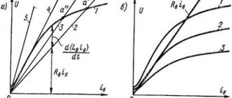
The external characteristic is the dependence of the voltage at the generator terminals on the load current. This characteristic corresponds to the natural operating conditions of the machine, i.e. the machine is unregulated (the excitation circuit resistance rв is constant) and is removed at a constant rotation speed.
For independent excitation generators at constant rв, the excitation current Iв is also constant. The external characteristics of such a generator are shown in Fig. 145.
Curve 1 represents an external characteristic taken to reduce the voltage. To remove this characteristic, such a current is set in the excitation winding so that when the generator is idling, the voltage at its terminals is equal to the nominal one. Then the generator load increases while the current in the field winding remains constant. With increasing load (armature current
generator Iа) increases both the voltage drop in the resistance of its winding and the demagnetizing effect of the armature reaction, which causes a decrease in voltage. When the load changes from zero to nominal, the voltage at the generator terminals decreases by the amount ΔUpn.
When taking the voltage increase characteristic (curve 2), the excitation current is set such that, at the rated load of the generator, the voltage at its terminals is equal to the rated one, after which the generator load is reduced.
As the load (armature current) decreases, both the voltage drop in the armature winding resistance and brush contacts and the demagnetizing effect of the armature reaction also decreases, causing the voltage to increase. When the load changes from nominal to 0, the voltage at the generator terminals increases by the amount ΔUpn. Due to the saturation of the steel, the increase in voltage will be less than the decrease, so. the demagnetizing effect of the armature reaction will be more pronounced, the lower the degree of saturation of the steel.
In parallel excitation generators, with a constant resistance of the excitation circuit gv, the excitation current does not remain constant, since it depends on the voltage at the generator terminals, which changes as the load changes. In independent excitation generators, an increase in load causes a decrease in voltage under the influence of a voltage drop in the machine resistance and armature reaction (curve 1 in Fig. 146).
In parallel excitation generators, as the voltage decreases, the excitation current also decreases, which causes a decrease in the magnetic flux and a decrease in voltage. Consequently, with increasing load, the voltage at the terminals of a generator of this type decreases to a greater extent (curve 2) than in independent excitation generators, since, in addition to the voltage decrease due to the voltage drop, in the machine resistance and armature reaction, there is also a voltage decrease due to reducing the excitation current.
A decrease in the external load resistance causes an increase in the current to a certain value Imax, not exceeding the rated current by more than 2-2.5 times. With further decrease
external resistance, the current decreases and during a short circuit it will be significantly less than the rated one. A decrease in load resistance causes a decrease in excitation current, as the generator voltage decreases. If the excitation current has decreased so much that the machine is demagnetized, then e.g. d.s. decreases to a greater extent than the load resistance, which: causes a decrease in the current in the armature.
When the parallel excitation generator is short-circuited, the current Ib is zero, and the field winding does not create a magnetic flux. Therefore, there will be e in the armature winding. d.s. only from the residual magnetic flux E0,
having a small value, and, therefore, the short circuit current Ik will also be small.
Despite the low value of the steady-state short-circuit current, it cannot be said that for generators of this type the short-circuit mode does not pose a danger. In the event of a sudden short circuit of such a generator, the current in the excitation winding cannot instantly decrease to zero, just like the magnetic flux. Therefore, a large e will be induced in the armature winding at the moment of a short circuit. d.s. and a current flows many times greater than the rated one, as a result of which intense sparking is created under the brushes, turning into a circular fire, and the machine can be disabled.
External characteristics
to increase the voltage of the parallel excitation generator (curve
3)
has the same form as that of the independent excitation generator.
For a series excitation generator, the external characteristic is shown in Fig. 147. In generators of this type, the excitation current is equal to the armature current (Iв=Iя), and during idling (Iа=0) an e will be created in the armature winding. d.s. due to residual magnetism Eo;
As the load increases, the current in the field winding will also increase, which causes an increase in e.
d.s. (curve 1).
The voltage at the generator terminals under load is less than e.
d.s. due to the voltage drop in the machine resistance and the armature reaction (curve 2).
Thus, in a series excitation generator, the voltage changes sharply with changes in load, so they are not widely used.
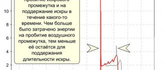
In mixed excitation generators, consonant and counter-connection of series and parallel windings is possible.
When the excitation windings are switched on concordantly, the resulting magnetizing force creating a magnetic flux is equal to the sum of the magnetizing forces of the parallel and series windings, and when switched on oppositely, it is the difference between these magnetizing forces.
In Fig. 148 shows the external characteristics of the mixed excitation generator.
An increase in the load of such a generator causes a decrease in the voltage at its terminals due to a voltage drop in its resistance and armature reaction. However, as the load increases, the current in the series field winding also increases. Therefore, when the windings are switched on in agreement, an increase in load will cause an increase in magnetic flux and e. d.s. armature windings. If e. d.s. with increasing load increases by an amount equal to the decrease in generator voltage due to the voltage drop in its resistance and armature reaction, then the voltage at the generator terminals will practically remain unchanged when the load changes from no-load to nominal (curve 1).
Such a generator, called normally excited, does not require a change in the excitation current when the load changes. With a decrease in the number of turns of the series winding, e. d.s. with increasing load it will increase to a lesser extent and will not compensate for the decrease in voltage, so the voltage at the generator terminals will decrease (curve 2), i.e. the generator is underexcited. If the number of turns of the series field winding is greater than that corresponding to the normal excitation of the machine, then the generator will be overexcited and the voltage at its terminals will increase with increasing load (curve 3).
When the excitation windings are turned on oppositely, the external characteristic is similar to this dependence for the parallel excitation generator (curve 4), however, the maximum /m and short circuit currents Ik for this generator will be less than the corresponding currents of the parallel excitation generator due to the demagnetizing effect of the magnetizing forces of the series winding.
Most often, normally excited generators are used, as well as overexcited generators, which make it possible to compensate for the voltage drop in the line, connecting wires, etc. so that the voltage across the load remains constant when the current changes.
Generators with counter-connected excitation windings do not provide constant voltage and are not widely used. They are used in cases where it is necessary to limit short circuit currents (for example, during electric welding).
The regulating characteristic of the generator shows to what extent the current in the field winding should be changed so that the voltage at the generator terminals remains constant when the load current changes.
Thus, the regulating characteristic of the generator is the dependence of the excitation current on the load current, taken at a constant voltage at the generator terminals
In generators of independent and parallel excitation! By increasing the load current, it is necessary to increase the excitation current in order to compensate for the voltage drop across the internal resistance of the machine and the demagnetizing effect of the armature reaction flux to ensure constant voltage.
In mixed excitation (normally excited) generators, the voltage does not change when the load changes, and, therefore, there is no need to regulate the excitation current, i.e., the regulation characteristic in such generators does not make sense, since the excitation current is constant when the load current changes.
Previous | Contents | Next >>
Alternator Design
In the most general case, the most commonly used three-phase alternating current generator consists of a salient-pole rotor with one pair of poles (low-power high-speed generators) or 2 pairs of them, arranged crosswise (the most common generators with powers up to several hundred kilowatts. This design not only allows for more efficient use material, but also for an industrial AC frequency of 50 Hz gives an operating rotor speed of 1500 rpm, which is in good agreement with the traction speed of diesel engines of this power), as well as a stator with 3 (in the first case) or 6 (in the second) power windings and poles. The voltage from the power windings is that which is supplied to the consumer.
The rotor can be made with permanent magnets only for very low-power generators; in all other cases it has a so-called winding. excitation winding, that is, it is a direct current electromagnet, powered in a rotating rotor through a brush-commutator assembly with simple ring contacts that are more resistant to wear than the split lamella commutator of DC machines.
In any powerful alternating current generator with an excitation winding on the rotor, the question inevitably arises: what magnitude of excitation current should be supplied to the coil? After all, the output voltage of such a generator depends on this. And this voltage must be maintained within certain limits, for example, 380 Volts, regardless of the current in the consumer circuit, a significant value of which can also significantly reduce the output voltage of the generator. In addition, the load across phases can generally be very uneven.
This issue is solved in modern generators, as a rule, by introducing electromagnetic current transformers into the output circuits of the generator phases, connected by secondary windings in a triangle or star, and producing at the output an alternating three-phase voltage with an amplitude of one - tens of volts, strictly proportional and phase-matched with the value of the load current of the phases generator - the greater the currently consumed current in a given phase, the greater the voltage at the output of the corresponding phase of the corresponding current transformer. This achieves a stabilizing and auto-regulating effect. All three regulating phases from the secondary windings of the current transformers are then connected to a conventional 3-phase rectifier of 6 semiconductor diodes, and its output produces a direct current of the required value, which is supplied to the rotor excitation winding through a brush-collector assembly. The circuit can be supplemented with a rheostat unit for some freedom in regulating the excitation current.
In outdated or low-power generators, instead of current transformers, a system of powerful rheostats was used, with the isolation of the operating excitation current by changing the voltage drop across the resistor when the current through it changes. These schemes were less accurate and much less economical.
In both cases, there is the problem of the appearance of an initial voltage on the power windings of the generator at the moment it begins to operate - indeed, if there is no excitation yet, then the current in the secondary windings of the current transformers has nowhere to come from. The problem, however, is solved by the fact that the iron of the rotor yoke has some capacity for residual magnetization; this residual magnetization is sufficient to excite a voltage of several volts in the power windings, sufficient to self-excite the generator and reach its operating characteristics.
In self-excited generators, a serious danger is posed by the accidental supply of external voltage from an industrial electrical network to the stator power windings. Although this does not lead to any negative consequences for the generator windings themselves, the powerful alternating magnetic field from the external network effectively demagnetizes the stator, as a result of which the generator loses the ability to self-excite. In this case, an initial application of excitation voltage from some external source, for example, a car battery, is required; sometimes this procedure completely cures the stator, but in some cases the need for external excitation remains forever.
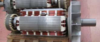
Main alternator
The main generator consists of a rotating magnetic field, as stated earlier, and a stationary armature (generator windings)
Operating principle of a DC generator
If a load is connected to the ends of the conductor loop, inside which a permanent magnet rotates, then alternating current will flow in it. This will happen because the poles of the magnet change places. The operating principle of alternating current generators, which are twin brothers of constant voltage machines, is based on this effect.
The whole trick, thanks to which the resulting current does not change direction, is to have time to switch the load connection points at the same speed as the magnet rotates. This task can only be accomplished by a collector - a special device consisting of several conductive sectors separated by dielectric plates. It is attached to the armature of an electric machine and rotates synchronously with it.
Electrical energy is collected from the armature by brushes - pieces of graphite, which has high electrical conductivity and a low coefficient of sliding friction. At the moment when the current-carrying sectors of the collector change places, the induced EMF becomes zero, but it does not have time to change sign, since the brush is transferred to the current-collecting sector connected to the other end of the conductor.
Read also: How to break through a Hyundai Solaris catalyst
Detailed instructions will tell you how to find possible generator malfunctions and repair them.
As a result, the output of the device produces a pulsating voltage of the same magnitude. To smooth out voltage ripple, several armature windings are used. The more there are, the lower the voltage surges at the generator output. The number of current-collecting sectors on the collector is always twice as large as the armature windings.
Removing the generated voltage from the armature winding, and not the stator, is the fundamental difference between a DC machine and an AC machine. This also predetermined their significant drawback: friction losses between the brushes and the commutator, sparking and heating.
Generator malfunctions and ways to eliminate them
The electrical equipment of a car tends to break down. In this case, the greatest problems arise with the battery and generator.
If any of these elements fails, operation of the vehicle in normal operating mode becomes impossible or the vehicle becomes completely immobilized.
All generator breakdowns are divided into two categories:
- Mechanical
. In this case, problems arise with the integrity of the housing, springs, belt drive and other elements that are not related to the electrical component. - Electrical
. These include malfunctions of the diode bridge, wear of the brushes, short circuits in the windings, breakdowns of the regulator relay, and others.
Now let's look at the list of faults and symptoms in more detail.
1. There is insufficient charging current at the output:
- Drive belt slipping. The solution is to tighten the belt and check the bearings for serviceability; the symptoms are whistling of the generator belt.
- Brushes stuck. First, you should clean the brush holder and brushes from dirt and make sure that the force is sufficient.
- Break in the excitation chain, burning of the contact wheels. The first problem is solved by finding and eliminating the break, and the second by stripping and grooving the slip rings (if required).
- Failure of the voltage regulator.
- The rotor touches the stator pole.
- Open circuit connecting the generator and battery.
2. Second situation.
When a car alternator produces the required level of current, but the battery still does not charge.
The reasons may be different:
- Poor quality of drawing the ground contact between the regulator and the main unit. In this case, check the quality of the contact connection.
- Voltage relay failure - check and replace it.
- If the brushes are worn out or stuck, replace them or clean them from dirt.
- The regulator's protective relay has tripped due to a short to ground. The solution is to find the location of the damage and fix the problem.
- Other reasons are oily contacts, breakdown of the voltage regulator, short circuit in the stator windings, poor belt tension.
3. The generator works, but makes a lot of noise.
Possible malfunctions:
- Short circuit between stator turns.
- Wear of the bearing seat.
- Loosening the pulley nut.
- Bearing failure.
Repairing a car generator should always begin with an accurate diagnosis of the problem, after which the cause is eliminated through preventive measures or replacing the failed unit.
Connection diagrams
According to the number of phases used, all generating sets are divided into two groups:
- single-phase;
- three-phase.
Single phase generator
Single-phase equipment connection diagram
This type of device is used to work with any electricity consumers, the main thing is that they are single-phase.
The simplest designs consist of:
- magnetic field;
- scrolling frame;
- collector device designed to drain current.
Due to the presence of the latter, as a result of frame scrolling through the brushes, constant contact with the frame is formed. The parameters of the current, which changes taking into account the harmonic law, will be different and are transmitted to the brush assembly, as well as to the voltage consumer circuit. Today, single-phase units are the most popular type of autonomous power source. They can be used to connect almost all household electrical appliances.
Three phase generator
This type of device belongs to the class of universal, but more expensive units. A distinctive feature of three-phase generators is the need for constant and expensive maintenance. Despite this, this type of installation is most widespread.
This is due to the following advantages:
- The unit is based on a rotating circular magnetic field. This provides the opportunity for good savings in equipment development.
- Three-phase generators consist of a balanced system. This ensures the service life of the unit as a whole.
- In the operation of a three-phase device, two voltages are used simultaneously - linear and phase. Both are used in a single system.
- One of the main advantages is increased economic performance. This ensures a reduction in the material consumption of power wires, as well as transformer units. Thanks to this feature, the procedure for transmitting electricity over long distances is simplified.
Star connection diagram
This type of connection involves electrically connecting the ends of the windings at a certain point, which is called “zero”. When making this connection, the load can be supplied to the generator unit via three or four cables. The conductors from the beginning of the windings are considered linear. And the main cable that comes from the zero point is zero. The voltage parameter between the conductors is considered linear (this value is 1.73 times higher than the phase value).
Star circuit for connecting three-phase equipment
One of the main features of this option is the equality of currents. The four-wire star type with a neutral cable is considered the most common. Its use helps prevent phase imbalance when connecting an asymmetrical load. For example, if it is active on one contact and reactive or capacitive on the other. When using this option, maximum protection of the switched-on electrical equipment is ensured.
Delta connection diagrams
This connection method is a series connection of the windings of a three-phase unit. The end of the first winding must be connected to the beginning of the second, and its contact to the third. Then the conductor from winding number 3 is connected to the beginning of the first element.
With this scheme, the linear cables are diverted from the connection points of the windings. The linear voltage parameter corresponds in magnitude to the phase voltage. And the value of the first current is 1.73 times higher than the second. The described properties are relevant only in the case of a uniform phase load. If it is uneven, then the parameters must be recalculated graphically or analytically.
Electrical diagrams of the unit's "triangle" connections
Characteristics of parallel excitation DC generator
Definition. Parallel excitation generators are generators whose excitation winding is powered by the EMF of the armature winding and is connected to the armature terminals of the machine parallel to the load circuit.
Parallel excitation generator circuit. The diagram is shown in Fig. 1.20. The armature current IА = I+ IВ at the brushes branches into the load current I and the excitation current IВ. Usually the excitation current is small and amounts to (0.01-0.05) Ir.nom. A rheostat RP is connected in series with the excitation winding to regulate the excitation. The rheostat allows you to change the excitation current and, therefore, the generator voltage.
The no-load characteristic of a self-excited generator is always removed with independent excitation (the field winding is disconnected from the armature and powered from an external source) and is therefore similar to the no-load characteristic of a generator with independent excitation.
Idle characteristics
U=f (Iв) at I=0 and n=const. In the process of self-excitation in parallel excitation generators Ia=Iв, and Iв=(0.02...0.03) Iн. Therefore, we can neglect the armature reaction and the voltage drop in the armature winding and assume that there is practically no difference between the no-load characteristics of the parallel excitation generator and the independent excitation one. It should be taken into account that this characteristic can only be measured in one quadrant, since the self-excitation process in this generator can only occur in one direction under the concordant action of the residual magnetic flux and the flux created by the excitation current, and in the straight section of the characteristic the generator voltage cannot be regulated like an independent excitation generator, which determines a smaller range of regulation of its voltage.
Load characteristic
U=f (Iв) with I=const and n=const. The load characteristics of a parallel excitation generator practically coincide with the characteristics of an independent excitation generator, since an increase in current Ia by the value of the excitation current during parallel excitation cannot have a noticeable effect on the generator voltage.
External characteristics
U=f (I) with rв=const and n=const (Figure 1) shows the effect of load changes on the generator voltage. In this case, the excitation current is not regulated using a control rheostat. It should be taken into account that with independent excitation
and with parallel excitation
The last equality means that when the external characteristic is removed, the excitation current of the generator changes in proportion to the voltage on the generator. Thus, a decrease in the voltage of the parallel excitation generator with an increase in its load is caused not only by the demagnetizing effect of the armature reaction and the voltage drop in the armature circuit, but also by a decrease in the excitation current. Therefore, the external characteristic of the parallel excitation generator (Figure 1) (curve 1) is located below the external characteristic of the independent excitation generator (curve 2).
In a parallel construction generator, the load current I will increase only up to a certain critical value Icr = (2. 2.5) In, after which it will begin to decrease to Iko M
1, then the speed of the electric motor will begin to decrease.
At the same time it decreases against e. d.s., and the current in the armature winding, according to expression (22), will increase, which will cause an increase in torque. The number of revolutions will decrease until the torque becomes equal to the moment of resistance M c2
.
When the moment of resistance decreases, the reverse process occurs. If the moment of resistance becomes less than the torque developed by the electric motor, then the rotation speed of the latter will begin to increase. This will cause an increase in counter e. d.s., which means a decrease in current and torque. The process will stop when the torque becomes equal to the resistance moment on the motor shaft.
28. Electromechanical (speed) and mechanical characteristics of a series-excited DC motor.
Series-excited commutator motors are more often used in uncontrolled electric drives. Their advantage is the ability to simultaneously provide large starting torque and high idle speed, which facilitates their use as traction motors in transport or actuator motors for mechanisms with a wide range of speeds. Recently, such motors have found application in household appliances. For example, in the drum drive of a washing machine, where these motors are used and controlled
The equivalent circuit of the engine, to a first approximation, can be presented in the form of Fig. 2.12, where, in addition to the notation adopted in the previous paragraph, it is designated R
W,
L
W – active resistance and inductance of the short-circuited eddy current circuit.
Rice. 2.12. Equivalent circuit of a series-excited DC motor
From the theory of electrical machines it is known that eddy currents are formed in the poles and in the magnetic circuit of the motor with a rapid change in flux. In high-power engines, the effect of a short-circuited circuit on dynamic properties can be significant. However, for the class of drives under consideration with power up to several kilowatts, this influence can be neglected. Then, in accordance with the equivalent circuit and taking into account expression (2.3), the voltage equation of the armature circuit will take the form
Car alternator malfunctions
| VISIBLE PROBLEM | CAUSE | SOLUTION METHOD |
| The charge indicator lamp does not light up when the ignition is turned on. | The battery is discharged or faulty | Charge or replace the battery |
| The lamp on the dashboard is burnt out | Replace | |
| There is no contact of the ground wire with the rear of the generator | Check the reliability of the ground contact, clean and tighten the bolts securing the ground wire | |
| Violation of the integrity of the wire between the lamp connection terminal on the generator and the instrument panel | Check with a voltmeter or ohmmeter according to the electrical diagram | |
| The connectors between the generator and the dashboard are not connected | Check and, if necessary, replace connectors | |
| The brushes do not fit tightly to the slip rings (“stuck” or worn out) | Check the length (min=5 mm) and freedom of movement of the brushes in the brush holder | |
| Voltage regulator defective | Replace voltage regulator | |
| Severe wear on the rotor rings | Check and, if necessary, replace rotor rings | |
| Broken generator rotor windings | Check the rotor and replace if necessary. | |
| The charge indicator lamp goes out when the engine speed increases, but the battery is not charging | The V-belt tension is loose | Tension the V-belt |
| Broken diodes of the diode bridge | Check and replace diode bridge | |
| Voltage regulator defective | Check and, if necessary, replace the voltage regulator relay | |
| The wire between the generator and the battery has poor contact | Check and replace the wire, and then check the diode bridge in the generator. | |
| The charge indicator lamp does not go out when the engine speed increases | The V-belt tension is loose | Tension the V-belt |
| Malfunction of the diode bridge or stator winding | Check and replace diode bridge or winding | |
| Voltage regulator defective | Check and, if necessary, replace the voltage regulator relay | |
| The wire between the generator and the control lamp has contact with ground | Find and repair the short circuit or replace the wiring harness, then check the diode bridge in the generator | |
| The charge indicator lamp lights up when the ignition is turned off. | Diode short circuit | Check the diodes and replace the diode bridge |
| The battery is boiling over | Voltage regulator relay malfunction | Replace the relay regulator and check the diodes, if necessary, replace the diode bridge |
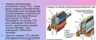
Story
Systems producing alternating current have been known in simple forms since the discovery of magnetic induction of electric current. Early machines were developed by pioneers such as Michael Faraday and Hippolyte Pixie.
Faraday developed a "rotating triangle" whose action was multipolar
- each active conductor was passed sequentially through an area where the magnetic field was in opposite directions. The first public demonstration of the most powerful "alternator system" took place in 1886. A large two-phase alternating current generator was built by British electrician James Edward Henry Gordon in 1882. Lord Kelvin and Sebastian Ferranti also developed an early alternator that produced frequencies between 100 and 300 hertz. In 1891, Nikola Tesla patented a practical "high frequency" alternator (which operated at a frequency of about 15,000 hertz). After 1891, multiphase alternators were introduced.
The principle of operation of the generator is based on the action of electromagnetic induction - the occurrence of electrical voltage in the stator winding located in an alternating magnetic field. It is created using a rotating electromagnet - a rotor - when direct current passes through its winding. The alternating voltage is converted to direct voltage by a semiconductor rectifier.
Operating modes
To understand the operating features of a car generator, it is important to understand the features of each mode:
- When starting the engine, the main consumer of electrical energy is the starter. A feature of the mode is the creation of increased load, which leads to a decrease in the voltage at the battery output. As a result, consumers draw current only from the battery. That is why in this mode the battery is discharged with the greatest activity.
- After starting the engine, the car generator switches to power source mode. From this moment on, the device provides the current necessary to power the load in the car and recharge the battery. As soon as the battery reaches the required capacity, the charging current level decreases. In this case, the generator continues to play the role of the main power source.
- After connecting a powerful load, for example, air conditioning, interior heating, etc., the rotor rotation speed slows down. In this case, the car generator is no longer able to cover the current needs of the car. Part of the load is transferred to the battery, which operates in parallel with the power source and begins to gradually discharge.
https://youtube.com/watch?v=feRhd7xg6R0