As you know, an insulated neutral central line is not used in apartment or home electrical wiring. However, for transformers and high-voltage generators, it is an integral part of the entire electrical network.
In this article we will delve into the terminology and scope of the isolated neutral type.
Isolated Neutral Definition and Terminology
The term “isolated central neutral” is described in the PUE, chapter 1.7, paragraph 1,7,6, as well as in GOST 2009-009, 12.1. These legislative sources clearly state that an isolated neutral is the central neutral of a generator or transformer of an electrical network, which is not connected to a grounding device or is connected, but through safety or alarm devices.
Also, the central isolated neutral can be a certain point, which is the center of the connection of the cores according to the “star” scheme.
Some, even professional, electrical specialists are convinced that an isolated neutral is an IT grounding system, which is described in PUE 1,7,3.
However, this is false information and deeply misleading, since the same paragraph of the PUE states that this system is used exclusively for power networks up to one kV.
In addition, paragraph 1,7,2 states that, depending on safety, isolated installations are divided into four categories from isolated to solidly grounded, as well as up to one kV and above.
Based on the above-described points of the isolated PUE, the conclusion follows: the isolated central neutral and the solid grounding system are completely different devices with different types of applications.
What is the definition of an isolated neutral
In the operating rules for electrical installations (PEU), there is a definition of what a circuit with an isolated neutral is. Let's consider what is called an IT scheme. This is a system in which the neutral wire of the generator or transformer is not connected to the ground electrode. It can be connected to the ground loop by connecting signaling, measuring, protection or similar devices to zero. All these devices must have high resistance.
A system with an isolated neutral can be represented by a three-phase network, the transformer winding in which is connected by a delta, but it can also be a star. And resistors extend from the line, connected to ground, and capacitors stand parallel to the resistance. Through which leakage currents flow in a cable or overhead line, they can be represented by two components. One of which is active, and the second is reactive.
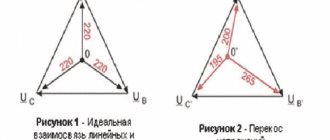
Since the resistance of undamaged insulation is about a megaohm. With such resistance, the leakage current is very small and is calculated according to Ohm's law. I=U/R, and with a resistance value of 0.5 MΩ and a voltage of 220 V, it is 0.44 Ma. The reactive component is represented as a capacitor. One cover is the line wire, and the other is the ground.
When there is a working three-phase network with an isolated neutral, the load between the phases is distributed evenly. When a breakdown of one phase to ground occurs, that is, single-phase faults to ground occur in networks with an isolated neutral.
In this case, a single-phase fault current occurs. Most often, a short circuit occurs on the body of the electrical consumer. The latter can be electric motors or metal structures.
If they are not grounded, then phase voltage or close to it appears on the device body. A person touching the body will be equivalent to touching a phase. Which is deadly. When a single-phase short circuit occurs in a network with an isolated neutral, the short-circuit current is small, its value is milliamps. At such currents it is impossible to install protective devices.
Therefore, to ensure shutdown, devices are used that automatically monitor the insulation condition. Such systems are installed when protection against ground faults is needed in networks with an isolated neutral.
Use of isolated neutral in networks up to 1000 V
Thanks to the use of an insulated neutral in the transformer, any possible probability of a voltage drop between the “zero” and “phase” conductors is eliminated.
Therefore, even accidental contact with a live electrical wire is safe.
To explain this process in technological language, you can familiarize yourself with the exact formula below, which demonstrates the equality of electric current upon contact with a person.
Ich = 3Uph/(3rch+ z)
As you can see, the electric current immediately returns to the isolated power source, rather than rushing into the ground through a conductor, in this case a person.
In addition, since the current resistance is about one hundred kOhms per phase conductor, then the current voltage will be equal to no more than a few milliamperes, which is absolutely safe.
In addition to the protective benefits of an insulated neutral described above, it is worth mentioning the minimization of any risks of current leakage into the metal frame of the transformer or generator.
Although the isolated protective relay or circuit breaker will not operate in this device, the insulator resistance control system will certainly operate, which will eliminate the possibility of an unsafe situation.
As a result of such well-established operation of an isolated electrical installation, an electrical network with three phases will continue to operate even in the event of a short circuit in one “phase” core.
In this case, the voltage of the electric flow in the active two phases will increase evenly and in case of accidental contact with one of them, the user will come under linear current voltage.
As you can see, due to the special contraction of the device, there is only one type of current voltage in the electrical network, in contrast to the isolated solid grounding system.
If the user wants to connect the system to the electrical network with a load on one active phase, it is recommended to always use step-down electrical installations, such as a 380 to 220 generator.
What it is
The definition of “isolated neutral” is given in Chapter 1.7. PUE, in paragraph 1.7.6. and GOST R 12.1.009-2009. Where it is said that the neutral of a transformer or generator is called isolated when it is not connected to a grounding device at all, or when it is connected through protection, measurement, and alarm devices.
The neutral is the point at which the windings of transformers or generators are connected when switched on in a star configuration.
There is a misconception among electricians that the abbreviated name for an insulated neutral is an IT system, according to the classification of clause 1.7.3. Which is not entirely true. The same paragraph states that the designations TN-C/CS/S, TT and IT are accepted for networks and electrical installations with voltages up to 1 kV.
In the same chapter 1.7 of the PUE there is paragraph 1.7.2. where it is said that with regard to electrical safety measures, electrical installations are divided into 4 types - isolated or solidly grounded up to 1 kV and above 1 kV.
Thus, there are some differences in the safety and application of such a network in different voltage classes, and calling a 10 kV line with an isolated neutral “IT system” is at least incorrect. Although schematically it’s almost the same.
Application of insulated neutral
An insulated central neutral has been actively used for urban transformers for power supply to residential neighborhoods, houses and domestic premises since the middle of the last century.
In addition, grounding systems are essential for power supply to buildings made of wooden materials, since they are in an area of increased risk of emergency and fire situations.
Experts report that most often a solid grounding system is used for apartment buildings, since if the user accidentally comes into contact with a live wire or surface with leakage current, the entire electrical network will continue to function, isolating only one phase, and all other residents of the house will not suffer from a complete power outage general power grid.
As you can see, in the case of a grounding system, DIP protection is necessarily activated, and if a dangerous situation arises for the safety of users, the machine will operate.
However, at the end of the last century, specialists abandoned this isolated system and began to use updated electrical installations.
At the moment, isolated central neutral is widespread in every electrical network, which requires an increased safety system. For example, where any possibility of proper grounding is excluded for various reasons.
These may include the following isolated electrical networks:
- On platforms, ships, vessels and all objects located in the sea or other waters, whose hull does not allow the network to be grounded.
- In places of work underground: wells or mines.
- In underground transport.
- On large installation cranes and other machines.
- In gasoline or diesel generators for domestic, non-industrial use. Also, according to PTEEP, paragraph 2.12.6, an insulated neutral can act as a consuming device of the network connecting contact to power electrical appliances up to twelve watts.
In networks up to 1 kV
General information
Let's figure out where, how and in what cases an insulated neutral is used in electrical installations with voltages up to 1000 V, the so-called IT system. In PUE chapter 1.7. clause 1.7.3. The definition given is similar to that given above, but it is slightly different. It says that housings and other conductive parts in IT system installations must be grounded. Let's see how it looks in the diagram.
Since the neutral of the IT network transformer is not connected to the ground, then, in simple terms, we do not have a dangerous potential difference between the ground and the phase wires. And accidentally touching 1 live wire in an IT system is safe. Due to the relatively low voltage, the capacitive conductivity of the phases is neglected here.
In networks with an isolated neutral, there are no distinct phases and zeros - both conductors are equal.
The current through the human body is equal to:
Ich = 3Uph/(3rch+ z)
Uph - phase voltage; rch is the resistance of the human body (assumed 1 kOhm); z is the total insulation resistance of the phase relative to ground (100 kOhm or more per phase).
The current in this case returns to the power source through the insulation of the wires, and not to the ground, as is the case with TN.
Since the insulation resistance is more than 100 kOhm per phase, the current through the body will be a few milliamps, which will not cause harm.
The next feature of this system is that the leakage currents to the frame and short-circuit currents to the ground will be low. As a result, protective automation (relay or circuit breakers) do not operate in the manner to which we are accustomed in networks with a solidly grounded neutral. But the insulation resistance monitoring system is triggered.
Accordingly, in case of a single-phase short circuit of a three-phase line, the system will continue to function. At the same time, the voltage on the two remaining wires increases relative to ground. If a person touches a phase wire, he comes under line voltage.
Due to this design, in a network with an isolated neutral there are no two types of voltage, unlike a solidly grounded one, where between the phases there is Ulinear (in everyday life 380V), and between the phase and zero there is Uphase (220V). To connect a single-phase load to the network with an IT system with a voltage of 380V, you can use step-down transformers of type 380/220 and connect devices between two phases to line voltage.
Scope of application
Let's talk about where this solution is used. This power supply system was used in domestic power grids to transmit electricity to residential buildings during the Soviet era. Especially for the electrification of wooden houses, where using a solidly grounded neutral increased the risk of fire due to ground faults.
From the point of view of electrical safety, the difference between an insulated and solidly grounded neutral in the power supply of houses is that if in an IT network one of the conductors touches grounded conductive parts, for example, wall fittings or water pipes, the network will continue to function due to low leakage currents.
Accordingly, neither residents nor anyone else will know about the problem until someone touches one of the wires and the pipeline at the same time and someone gets an electric shock.
In a system with a solidly grounded neutral, at least the differential protection will work, and if there is a “good” metal circuit, the circuit breaker will turn off. With the beginning of the mass construction of panel houses (the so-called Khrushchev houses), they abandoned it and in the 60-80s they switched to TN-C, and in the late 90s to TN-CS, read about the reasons below.
Currently, insulated neutral is used wherever it is necessary to ensure increased safety or where it is not possible to make normal grounding, namely:
- At sea - on ships, oil and gas production platforms, where using the platform body as a grounding is impossible due to anodic protection, and in places where current flows into the water it will begin to rust and rot intensively.
- In mines and other places of mining (with voltage 380-660V).
- In the underground.
- On lighting and control circuits in stationary cranes, etc.
- Also, in household gasoline, gas or diesel generators, there is an insulated neutral at the output terminals.
It can be found not only in the form that we have shown in the diagram above, but also in the form of step-down and isolation transformers, which are used to power portable lighting devices (no more than 50V or 12V PTEEP clause 2.12.6.) and other equipment or tools, including those used in confined and damp areas.
Let's sum it up
We have figured out why an insulated neutral up to 1 kV is needed, now we will list the advantages and disadvantages of a power supply system with an insulated neutral for electricians for dummies.
Benefits of use:
- Greater security.
- Greater reliability, which allows it to be used, for example, for lighting in hospitals.
- Economic factor - in a three-phase network with an isolated neutral, it is possible to transmit electricity through the minimum possible number of wires - three.
- The system will continue to operate during single-phase ground faults.
Flaws:
- In the event of a ground fault, the danger of use increases as the power supply continues.
- Small short-circuit currents.
- No sparks during primary short circuit.
Advantages and disadvantages of isolated neutral
Below we describe the pros and cons of using a central insulated neutral in networks up to 1000 V.
Advantages of an isolated neutral:
- High level of security for the user.
- Duration of reliable operation without faulty situations.
- Saving electricity consumption.
- Maintains operability even if there is a short circuit in one of the three phases.
Disadvantages of an isolated neutral:
- When one of the phases is short-circuited, the voltage in the current ones increases, which reduces the safety of use.
- Low current when closing.
- No signs at the first phase closure.
Solidly grounded neutral
A more progressive method is the solidly grounded neutral mode. In this case, the neutral of the generator or transformer is directly connected to the grounding device. In some cases, the connection is made using a low resistance, such as a current transformer. Unlike protective grounding, such neutral grounding is called working. The resistance value of grounding devices connected to the neutral should not exceed 4 Ohms in electrical installations with a voltage of 380/220 volts.
In electrical installations where a solidly grounded neutral is used, the damaged section must be quickly and reliably disconnected automatically in the event of a short circuit between the phase and the grounding conductor. In this regard, at voltages up to 1000 volts, equipment housings must be connected to the grounded neutral of the installations. This ensures that the damaged area is quickly disconnected in the event of a short circuit using an overcurrent relay or fuse.
Applications of insulated neutral for networks over 1000 V
For safety of use and reduction of consumables in electrical networks over 1000 V, solid grounding insulating systems are most often used.
However, it is worth noting that in some transformers the cores are connected in a “three corners” rather than a “star” pattern and the central neutral is not provided initially.
For high-voltage wire systems, insulated solid grounding is extremely necessary for stable operation of the electrical network, since thanks to it the current voltage during a phase short circuit is minimal, and even when one phase is disconnected, the other two will continue to operate.
In addition, even a single contact with an uninsulated high-voltage wire is mortally dangerous to human life, therefore the system for ensuring safety must not be neglected.
In addition to the above-described factors for the need to use insulation, there is another one associated with damage to one of the phases.
As is known, when a grounded phase is short-circuited through another in a transformer of high-voltage wires, a significant overload occurs, which leads to the destruction of insulation and an interphase short circuit.
To eliminate the slightest possibility of a grounded arc and the ensuing emergency consequences, the isolated central neutral must be connected to the “ground” through a special reactor that extinguishes the arc.
It must be selected and installed according to all the characteristics of a particular network so that it provides maximum protection and security.
The reactor described above for arc extinguishing contributes to the following processes:
- Reduces short circuit current.
- Destroys the arc by affecting its unstable physical characteristics.
- Reduces the risk of a repeat arc fault by slowing down the current rise after extinguishing.
- Reduces reverse current voltage.
Networks with isolated neutral
Networks with voltages up to 1 kV in our country are in the vast majority of cases operated in the solidly grounded neutral mode. This means that the neutral point of the secondary winding of the transformer in the substation is short-circuited to the grounding device.
Thus, between any phase in a 0.4 kV network and the ground there is always a voltage, called “phase” and having a value of 220 volts. But in some cases, 0.4 kV networks with an isolated neutral are used (IT system).
This can happen, for example, if the secondary windings of the transformer are connected in a “triangle” and the neutral point is simply missing. Or, suppose, for some reason, an emergency network shutdown associated with a short circuit to ground is unacceptable.
Due to the fact that there is no electrical connection between the network conductors and the ground in IT networks, a single-phase ground fault can no longer be called a “short”. However, one cannot assume that there will be no leakage current at all with such a short circuit.
The fact is that the insulation of the supply cable cores is not an absolute dielectric. The same can be said about all the insulators available on the network, as well as other insulating materials.
They all have some kind of minimum conductivity, so there is always leakage current through them. And the greater the length of the line, the greater it is. In addition, each core of the supply cable can be thought of as one of the plates of a capacitor.
The second layer is the ground, and the dielectric is the insulating layer and the air layer between the cable and the nearest live parts that are not energized. The capacity of such a capacitor will be greater, and the resistance of the leakage circuit will be less, the more extended the line is.
Taking into account the insulation resistance and specific electrical capacity, a network with an isolated neutral can be represented as an equivalent circuit, as shown in the figure. Each phase is connected to ground through a capacitor and resistor connected in parallel.
Thanks to these elements of the replacement circuit, in the event of a single-phase fault to ground in the network, a leakage current occurs along the circuit: “damaged phase - ground - elements of the replacement circuit - serviceable phases.” Under almost any conditions in networks with an isolated neutral of 0.4 kV, this current is small and can be calculated in milliamps.
Despite the fact that the current of a single-phase ground fault in networks with an isolated neutral is relatively small, and the network can still operate after its occurrence, such a fault leads to emergency operation of the network.
It must be taken into account that in such networks, in the event of a single-phase ground fault, the voltage between the serviceable phases and the ground increases sharply. In fact, this voltage becomes equal to linear - 380 volts. This poses a risk of electric shock to electrical and electrical engineering personnel.
And, in addition, a single-phase ground fault in networks with an isolated neutral contributes to the breakdown of insulation and the occurrence of a ground fault in two other phases.
In essence, there is the possibility of a short circuit between phases with characteristic overcurrents, for protection from which circuit breakers or fuse links will be required.
At the same time, the small value of the single-phase ground fault current in IT networks becomes the reason that it is simply impossible to detect such a fault and turn it off using circuit breakers or fuses - additional relay equipment is required to signal an accident.
Thus, IT networks require more protection and signaling devices, and increased qualification requirements can be placed on the personnel servicing such networks.
Example IT diagram
For an example of a practical circuit, see the fragment of the DC rectifier cabinet wiring diagram. Please note that the power is supplied from a 3-phase 230 V network, each of the three rectifiers is connected between phases, in line voltage.
An example of constructing a circuit with an IT grounding system
In fact, there is a protective grounding wire, it comes from the supply generator, but it only serves to ground the power supply housings.
In this case, the output voltage is constant 12 V, but can be anything! And the “minus” of all power supplies is grounded. The outputs of each power supply are supplied to the loads through circuit breakers (not shown).
Isolated neutral. Device and operation. Application
Isolated neutral - in the process of transmission, distribution and consumption of electrical energy, a symmetrical 3-phase system is used.
Such symmetry can be achieved by bringing line and phase voltages to the same position. Therefore, a uniform current load and an equal phase shift of voltages and currents are created in all phases. But during the operation of such a system, emergency modes often arise, leading to various malfunctions of the conductors. As a result, a violation of the symmetry of the three-phase system occurs. Such violations must be quickly corrected. This is greatly influenced by the speed of relay protection.
Its correct functioning depends on the neutrals, which can be insulated or solidly grounded. Each of them has its own disadvantages and advantages, and is used in appropriate operating conditions. Its normal operation depends on the technical condition of the relay protection.
Device
An isolated neutral creates a mode that has found application in Russian power systems for transformers and generators. Their neutral points are not connected to the ground loop. In high voltage networks (from 6 to 10 kV), a neutral point is not necessary, since the transformer windings are made according to a delta circuit.
According to the rules, it is possible to limit the isolated neutral mode by the capacitor current. This current occurs when one phase is short-circuited.
The fault current can be compensated by using arc suppression reactors in the following cases:
- More than 30 A, voltage from 3 to 6 kV.
- More than 20 A, voltage 10 kV.
- Current is more than 15 A, voltage is from 15 to 20 kV.
- Current is more than 10 A, voltage is from 3 to 20 kV, with power transmission line supports.
- All power supply networks are 35 kV.
- In the “generator-transformer” group with a load of 5 A and a voltage at the generator from 6 to 20 kV.
It is possible to compensate for the fault current to the ground loop by replacing it with grounding the neutral with a special resistor. In this case, the order of operation of the relay protection will change. The insulated neutral was grounded for the first time in electrical devices with low voltage.
In domestic power supply networks, isolated neutral is used in:
- 2-wire DC networks.
- 3-phase AC networks up to 1 kV.
- 3-phase networks from 6 to 35 kilovolts, subject to permissible fault current.
- Low-voltage networks with protective devices in the form of separating transformers, protective insulation, to create safe human conditions.
Operating principle
An insulated neutral is used in power supply circuits in cases where the secondary windings of transformers are connected in a delta circuit, as well as when it is impossible to turn off the power in case of an emergency. Therefore there is no neutral point.
A phase-to-ground fault is not considered a short in a network diagram with an isolated neutral, since there is no connection between the ground and the network conductors. But this does not mean that there will be no leakage current during a short circuit.
This is explained by the fact that cable insulation is not an absolute dielectric, like other insulators that have a certain minimum conductivity. The longer the line, the higher the leakage current. Let's imagine a cable core as a capacitor plate. The second covering will be the ground. The air and insulation will be a dielectric between the live parts without voltage and the cable. The longer the transmission line, the higher the capacitance of such an imaginary capacitor.
A network with an isolated neutral is an equivalent circuit, taking into account the specific electrical capacity of the network and the insulation resistance. This is shown in the picture.
Such circuit components create leakage current. Under various conditions in such 380-volt networks, the leakage current is insignificant, amounting to several milliamps. Despite this, such a short circuit leads to a network failure, although the network may still work for some time.
We must not forget that in similar networks, when a 1-phase is shorted to ground, the voltage between the ground and the serviceable phases increases significantly. This voltage approaches 380 volts (line voltage). This fact may result in electrical shock to electrical workers.
Also, an isolated neutral, when one phase is shorted to ground, contributes to the breakdown of insulation and the appearance of a short circuit in other phases, that is, an interphase short circuit with high currents can occur. To provide protection in such a situation, fuse links or circuit breakers are needed.
A double ground fault is very dangerous for network maintenance workers. Therefore, if there is a single-phase fault in the network, then such a network is considered emergency, since safety conditions are sharply reduced. The presence of “ground” increases the risk of electric shock when touching live parts. Therefore, short circuits of even one phase to earth must be eliminated immediately.
The insignificant value of the 1-phase fault current with an isolated neutral is the reason for such a factor that such a fault cannot be turned off by fuses and circuit breakers. Therefore, auxiliary relay electrical installations will be required that will warn of emergency mode.