Color of zero, neutral
The “zero” wire should be blue
. In the distribution board it must be connected to the zero bus, which is designated by the Latin letter N. All blue wires must be connected to it. The bus is connected to the input via a meter or directly, without additional installation of the machine. In the distribution box, all wires (except for the wire from the switch) of blue color (neutral) are connected and do not participate in switching. To the sockets, the blue “zero” wires are connected to the contact, which is designated by the letter N, which is marked on the back of the sockets.
The designation of the phase wire is not so clear. It can be either brown, or black, or red, or other colors besides
blue, green and yellow. In an apartment switchboard, the phase wire coming from the load consumer is connected to the lower contact of the circuit breaker or to the RCD. In switches, the phase wire is switched; during switching off, the contact closes and voltage is supplied to consumers. In phase sockets, the black wire must be connected to the contact marked with the letter L.
How to find ground, neutral and phase in the absence of a designation
If there is no color marking of the wires, then you can use an indicator screwdriver to determine the phase; upon contact with it, the screwdriver indicator will light up, but not on the neutral and ground wires.
You can use a multimeter to find ground and neutral. We find the phase with a screwdriver, fix one contact of the multimeter on it and “probe” the wires with another contact; if the multimeter shows 220 volts, this is neutral; if the values are below 220, then it is grounding.
Letter and numeric wire markings
The first letter “A” denotes aluminum as the core material; in the absence of this letter, the core is copper.
The letters “AA” denote a multi-core cable with an aluminum core and an additional braid made of it.
"AC" is indicated in case of additional lead braiding.
The letter “B” is present if the cable is waterproof and has an additional double-layer steel braid.
“BN” cable braid does not support combustion.
"B" polyvinyl chloride shell.
"G" does not have a protective shell.
“g” (lowercase) bare, waterproof.
“K” is a control cable wrapped with wire under the top sheath.
"R" rubber casing.
"NR" non-flammable rubber casing.
Wire colors abroad
The color marking of wires in Ukraine, Russia, Belarus, Singapore, Kazakhstan, China, Hong Kong and the countries of the European Union is the same: Ground wire - Green-yellow
Neutral wire - blue
phases are marked with different colors
The neutral designation is black in South Africa, India, Pakistan, England, but this is the case with old wiring.
Currently the neutral is blue.
In Australia it can be blue and black.
In the USA and Canada it is designated white. You can also find gray labeling in the USA.
The ground wire is yellow, green, yellow-green in color everywhere, and in some countries it may also be without insulation.
Other wire colors are used for phases and may be different, except for the colors indicating other wires.
13 ways to save electricity
Color coding abroad
The yellow and green marker of the grounding wire PE and the blue working zero N are designated absolutely identically in all CIS countries, while they are clearly unified with the countries of the European Union. The color designation of the phase wire varies slightly, but this is not of fundamental importance in terms of electrical safety.
In other countries, such as Brazil, the USA, Canada, Australia and New Zealand, the PE ground wire, along with the yellow-green color, can be simply green, and the working zero N is indicated by any of black, white or blue.
In the UK, Australia, New Zealand, Canada and the USA, the PE conductor may not have any insulation at all.
Important! Previously in the USSR, according to the old edition of the PUE, there was color marking that was radically different from today. Thus, the black color indicated the solidly grounded neutral and all grounding conductors, and the white color of the wire corresponded to the working zero.
It is worth remembering that electrical installation work requires an electrician to have knowledge of electrical installations and safety precautions. Once you clearly know the markings, the question of how to choose the right wire color during work will no longer arise, and repairing electrical wiring or installing equipment will become not only safe, but also convenient.
Color of wires plus (+) and minus (-) in DC networks
Is the red wire positive or negative? Such questions arise when working with DC electrical circuits.
Red
To remember which plus is red or black, they use the name of a well-known international organization - the Red Cross. This phrase suggests that red means plus.
Black
Black color indicates the negative conductor. These markings can be seen on typical household equipment:
- power supplies;
- audio, video equipment;
- other devices with electronic software control units.
Plus
The polarity of conductors must be observed when repairing standard electrical equipment of cars. In some situations, confusion with plus and minus is accompanied by a violation of the functional state.
Minus
The high power of connected consumers increases the responsibility for performing repair and adjustment work. In such situations, it is necessary to eliminate errors in determining polarity. Strong direct current is used to supply electricity:
- warehouse and municipal transport;
- lifting mechanisms;
- sensors and automation.
DC network
A DC network differs from an AC network in that it contains two conductors: plus and minus. The core of the positive conductor is marked in red, and the core of the negative conductor is marked in blue.
The practice of color separation of wires is familiar to professionals and amateurs; it is actively used in electrical engineering, but still you should not blindly trust the markings. Backing up with a measuring device is a thoughtful and balanced move when installing electrical networks; you should not neglect it.
Find the neutral wire in the apartment
According to the rules, the housing of the access panel is grounded. It is carried out using a solid-sized terminal, tightened with a powerful bolt in old-built houses; it will be easier for residents of modern buildings to navigate by the number of cores. The zero bus has the largest number of connections, the phases are separated into apartments (good electricians hang up stickers A, B, C; evil ones don’t). We can easily follow the layout of circuit breakers and meters.
230 volt UK plug
In each case, the common wire will be zero. Color does not play a decisive role. Although according to standards, modern cables are equipped with colored insulation
Please note that if the house is equipped with grounding, there will be at least 5 cores at the input. The panel body is mounted on a yellow-green one. The neutral wire will serve to drain the operating current from the devices (closes the circuit)
Merging branches on the consumer side is prohibited. Here are three rules to help you understand the entrance panel (please note, according to the rules, the tenant should not show his nose there at all - we have warned):
The neutral wire will serve to drain the operating current from the devices (closes the circuit). Merging branches on the consumer side is prohibited
Here are three rules to help you understand the entrance panel (please note, according to the rules, the tenant should not show his nose there at all - we have warned):
- The circuit breaker breaks the phase. There are two-pole models; they are used relatively rarely for rooms with particular danger (bathroom). Therefore, by the position of the wire you can tell: this is a phase. Then you can turn off the machine and ring the wire on the side of the apartment. It will definitely give the phase position.
- The voltage between the neutral wire and any phase is 230 volts. Based on the key characteristic, we will select a vein that gives the specified difference to another. The spread between phases is 400 volts. The percentage values are 10 percent higher; Russian networks are trying to meet European standards.
- We use current clamps to measure the values on the conductors. For each phase there will be a certain value, the sum of which (in three) should flow back to the network via zero (or a suitable phase). Grounding is rarely used; the current here will be close to zero if the branches are evenly loaded. The place where the value is greatest is traditionally the neutral conductor.
- The grounding terminal of the distribution board is visible. The sign will help you find the neutral wire in houses with NT-CS. In other cases, grounding is supplied here.
Wire color coding
Anyone who has ever dealt with wires and electricity has noticed that conductors always have different insulation colors. This was done for a reason
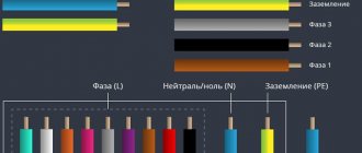
The colors of the wires in electrics are designed to make it easier to recognize the phase, neutral wire and ground. They all have a certain color and are easily distinguished during operation. The color of the phase, neutral, and ground wires will be discussed further.
How phase wires are painted
When working with wiring, phase wires pose the greatest danger. Touching the phase, under certain circumstances, can become lethal, which is probably why bright colors were chosen for them. In general, the colors of electrical wires allow you to quickly determine which of a bunch of wires are the most dangerous and work with them very carefully.
Coloring of phase wires
Most often, phase conductors are red or black, but other colors are also found: brown, lilac, orange, pink, purple, white, gray. Phases can be painted in all these colors. It will be easier to deal with them if you exclude the neutral wire and ground.
In the diagrams, phase wires are designated by the Latin (English) letter L. If there are several phases, a numerical designation is added to the letter: L1, L2, L3 for a three-phase 380 V network. In another version, the first phase is designated by the letter A, the second by B, and the third by C .
Ground wire color
By modern standards, the ground conductor is yellow-green. It usually looks like yellow insulation with one or two longitudinal bright green stripes. But there are also transverse yellow-green stripes in color.
Grounding may be this color
In some cases, the cable may only have yellow or bright green conductors. In this case, the “earth” has exactly this color. It is displayed in the same colors on diagrams - most often bright green, but it can also be yellow. Signed on circuit diagrams or on ground equipment in Latin (English) letters PE. The contacts to which the “ground” wire must be connected are also marked.
What color is the neutral wire?
Zero or neutral is blue or light blue, sometimes blue with a white stripe. Other colors are not used in electrical engineering to indicate zero. It will be like this in any cable: three-core, five-core or with a large number of conductors.
What color is the neutral wire? Blue or cyan
“Zero” is usually drawn in blue on diagrams and signed with the Latin letter N. Experts call it a working zero, since, unlike grounding, it participates in the formation of the power supply circuit. When reading a diagram, it is often defined as "minus", while the phase is considered "plus".
How to check the correctness of marking and wiring
Take a multimeter and/or an indicator screwdriver. It’s easy to work with a screwdriver: when you touch a phase, the LED built into the housing lights up. So it will be easy to identify phase conductors. If the cable is two-wire, there are no problems - the second conductor is zero. But if the wire is three-wire, you will need a multimeter or tester - with their help we will determine which of the remaining two is phase and which is zero.
Determining the phase wire using an indicator screwdriver
We set the switch on the device so that the selected jackal is more than 220 V. Then we take two probes, hold them by the plastic handles, carefully touch the metal rod of one probe to the found phase wire, the second to the supposed zero. The screen should display 220 V or the current voltage. In fact, it may be significantly lower - this is our reality.
If 220 V or a little more is displayed, this is zero, and the other wire is presumably “ground”. If the value is less, we continue checking. With one probe we again touch the phase, with the second - to the intended grounding. If the instrument readings are lower than during the first measurement, there is “ground” in front of you and it should be green. If the readings turn out to be higher, it means that somewhere there was a mistake with “zero” in front of you. In such a situation, there are two options: look for exactly where the wires were connected incorrectly (preferable) or simply move on, remembering or noting the existing position.
And, in conclusion, let me give you some advice: when laying wiring and connecting wires, always connect conductors of the same color, do not confuse them. This can lead to disastrous results - at best, equipment failure, but there may also be injuries and fires.
This is interesting: How to unscrew the valve axle box from the mixer if it is stuck?
Wire Classification Options
The typical cable name contains letters and numbers. By decoding these symbols you can find out the main characteristics of products in this category:
- conductor (shell) materials;
- number of cores;
- cross-sectional area;
- Extra options.
Example of decoding (AVBbv-ng):
- A – the core is made of aluminum (copper is not marked);
- B – insulating shells are made of PVC;
- BB – protection against mechanical damage, made of steel tape without a damping gasket;
- ng – components that prevent combustion have been added to the polymer shell.
Ground wire color
By modern standards, the ground conductor is yellow-green. It usually looks like yellow insulation with one or two longitudinal bright green stripes. But there are also transverse yellow-green stripes in color. This color can be grounding.
In some cases, the cable may only have yellow or bright green conductors. In this case, the “earth” has exactly this color. It is displayed in the same colors on diagrams - most often bright green, but it can also be yellow. Signed on circuit diagrams or on ground equipment in Latin (English) letters PE. The contacts to which the “ground” wire must be connected are also marked.
Sometimes professionals call the grounding wire “neutral protective”, but do not be confused. This is an earthen one, and it is protective because it reduces the risk of electric shock.
What color is the neutral wire?
Zero or neutral is blue or light blue, sometimes blue with a white stripe. Other colors are not used in electrical engineering to indicate zero. It will be like this in any cable: three-core, five-core or with a large number of conductors.
What color is the neutral wire? Blue or light blue. “Zero” is usually drawn in blue on diagrams and signed with the Latin letter N. Experts call it a working zero, since, unlike grounding, it participates in the formation of the power supply circuit. When reading a diagram, it is often defined as "minus", while the phase is considered "plus".
Color of zero, neutral
The “zero” wire should be blue
. In the distribution board it must be connected to the zero bus, which is designated by the Latin letter N. All blue wires must be connected to it. The bus is connected to the input via a meter or directly, without additional installation of the machine. In the distribution box, all wires (except for the wire from the switch) of blue color (neutral) are connected and do not participate in switching. To the sockets, the blue “zero” wires are connected to the contact, which is designated by the letter N, which is marked on the back of the sockets.
The designation of the phase wire is not so clear. It can be either brown, or black, or red, or other colors besides
blue, green and yellow. In an apartment switchboard, the phase wire coming from the load consumer is connected to the lower contact of the circuit breaker or to the RCD. In switches, the phase wire is switched; during switching off, the contact closes and voltage is supplied to consumers. In phase sockets, the black wire must be connected to the contact marked with the letter L.
How to find ground, neutral and phase in the absence of a designation
If there is no color marking of the wires, then you can use an indicator screwdriver to determine the phase; upon contact with it, the screwdriver indicator will light up, but not on the neutral and ground wires.
You can use a multimeter to find ground and neutral. We find the phase with a screwdriver, fix one contact of the multimeter on it and “probe” the wires with another contact; if the multimeter shows 220 volts, this is neutral; if the values are below 220, then it is grounding.
Letter and numeric wire markings
The first letter “A” denotes aluminum as the core material; in the absence of this letter, the core is copper.
The letters “AA” denote a multi-core cable with an aluminum core and an additional braid made of it.
"AC" is indicated in case of additional lead braiding.
The letter “B” is present if the cable is waterproof and has an additional double-layer steel braid.
“BN” cable braid does not support combustion.
"B" polyvinyl chloride shell.
"G" does not have a protective shell.
“g” (lowercase) bare, waterproof.
“K” is a control cable wrapped with wire under the top sheath.
"R" rubber casing.
"NR" non-flammable rubber casing.
Wire colors abroad
The color marking of wires in Ukraine, Russia, Belarus, Singapore, Kazakhstan, China, Hong Kong and the countries of the European Union is the same: Ground wire - Green-yellow
Neutral wire - blue
phases are marked with different colors
The neutral designation is black in South Africa, India, Pakistan, England, but this is the case with old wiring.
Currently the neutral is blue.
In Australia it can be blue and black.
In the USA and Canada it is designated white. You can also find gray labeling in the USA.
The ground wire is yellow, green, yellow-green in color everywhere, and in some countries it may also be without insulation.
Other wire colors are used for phases and may be different, except for the colors indicating other wires.
13 ways to save electricity
Phase conductor, its definition by color or otherwise
The phase is always mounted with wires whose insulation is painted in any color, but not blue or yellow and green: only green or only yellow. The phase conductor is always connected to the switch contacts. If during installation there are sockets that have a terminal marked with the letter L, it is connected to a conductor in black insulation. But it happens that the installation is carried out without taking into account the color marking of the phase, neutral and grounding conductors.
In this case, to determine the identity of the conductors, you will need an indicator screwdriver and a tester (multimeter). By the glow of the indicator of a screwdriver, which is touched to the current-carrying core, the phase wire is determined - the indicator lights up. Touching the grounding or grounding conductor does not cause the indicator screwdriver to light up. To correctly determine grounding and grounding, you need to measure the voltage using a multimeter. The readings of a multimeter whose probes are connected to the conductors of the phase and neutral wires will be greater than if the probes touch the conductors of the phase conductor and grounding.
Since the phase wire is previously clearly identified by an indicator screwdriver, the multimeter allows you to complete the correct determination of the assignment of all three conductors.
The letter designations printed on the wire insulation are not related to the purpose of the wire. The main letter designations that are present on the wires, as well as their contents, are shown below.
The colors adopted in our country to indicate the purpose of wires may differ from similar colors of wire insulation in other countries. The same wire colors are used in
- Belarus,
- Hong Kong,
- Kazakhstan,
- Singapore,
- Ukraine.
A more complete picture of the color coding of wires in different countries is given by the image shown below.
Wire color codes in different countries
In our country, color markings L, N in electrical equipment are specified by the GOST R 50462 - 2009 standard. The letters L and N are applied either directly to the terminals or to the equipment housing near the terminals, for example, as shown in the image below.
These letters denote neutral (N) and line (L - “line”) in English. It means "phase" in English. But since one word can take on different meanings depending on the meaning of the sentence, concepts such as lead or live can be applied to the letter L. And N in English can be interpreted as “#NULL” - zero. Those. On diagrams or devices, this letter means zero. Consequently, these two letters are nothing more than the designations of phase and zero in English.
Also taken from the English language is the designation of conductors PE (protective earth) - protective grounding (i.e. earth). These letter designations can be found both on imported equipment, the markings of which are made in Latin, and in its documentation, where the designation of the phase and neutral wire is done in English. Russian standards also require the use of these letter designations.
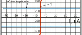
Since in industry there are also electrical networks and direct current circuits, the color designation of conductors is also relevant for them. Current standards require buses with a plus sign, as well as all other conductors and cores of positive potential cables, to be red. The minus is indicated in blue. As a result of this coloring, it is immediately clear where the potential is.
In order for readers to remember the color and letter designations, in conclusion we list them together once again:
the phase is designated by the letter L and cannot be yellow, green or blue in color.
The N ground, PE ground and PEN combined conductor use the colors yellow, green and blue.
Red and blue colors are used for conductors and buses.
Colors of DC buses and wires
It would not be superfluous to show the color designation of buses and wires for three phases:
The Electrician's Bible PUE (Electrical Installation Rules) states: electrical wiring along its entire length should make it possible to easily recognize the insulation by its color.
In a home electrical network, as a rule, a three-wire conductor is laid, each wire has a unique color.
- Working zero (N) is blue, sometimes red.
- The neutral protective conductor (PE) is yellow-green.
- Phase (L) – can be white, black, brown.
In some European countries there are constant standards for the colors of wires by phase. Power for sockets - brown, for lighting - red.
Electrical wire colors
Certain colors of electrical wires are chosen for a reason. Electrical wiring marked in different colors is needed for reliable electrical installation work in order to save yourself from electrical short circuits and electric shocks.
Electrical engineers used to work exclusively with two colors, black and white. This caused great inconvenience when connecting contacts. Marking the color of cables in electrical wiring allows you to identify the neutral wire, grounding and phase.
In accordance with the European standard, each electrical wire has its own color.
The ground wire is almost always marked yellow-green. The neutral color should be blue. The phase wire can be of various colors, ranging from brown to light green. In addition to color differences, there are letter markings, as well as using a screwdriver with an indicator.
how to deal with wiring
There is such a rather interesting book called PUE (Electrical Installation Rules). It describes how the wiring should be done. We are not interested in the whole book yet, let's look at how the wires are marked by color. Why was this marking invented? So that electricians understand each other without words.
For single-phase wiring with grounding, this color coding is adopted. The yellow, yellow-green or green (rarely happens, you have to be careful) wire is grounding. The blue or blue-white wire is the “zero” of the network. And the rest of the gamut (red, black, brown, orange, pink and other warm colors) is always a phase wire.
In a three-phase circuit, the color markings of the wires are slightly different. Blue - in the same way means zero (but not grounding!), each phase is indicated by its own color. Phase “A” is yellow, phase “B” is green, phase “C” is red.
The terminals for connecting the wiring are also marked. Terminal “0” or “N” - the neutral wire (blue or blue-white) is always connected to it. Terminal “L” - the phase wire (red, brown, etc.) is connected to it. The ground terminal is most often located on the metal body of the product and is often not marked. A yellow-green wire is connected to it.
The terminals for connecting three-phase wiring are also marked. But a little differently. The phases “A”, “B” and “C” and the neutral wire “N” or “0” are indicated there. Therefore, it is very important not to make a mistake - in a single-phase circuit the green wire is grounding, and in a three-phase circuit it is the phase wire.
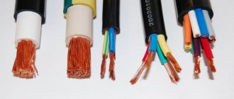
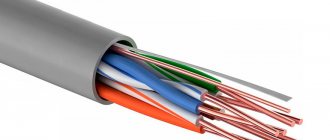
Distinguishing wires by insulation color in multi-core cables
Cables with a large number are used for laying AC networks. In these situations, it is possible to use different shades of the insulating layer. The color of the phase-zero-ground wires is important if the wiring is installed and serviced by different specialists. This allows you to get started right away.
Different shades of insulation save timeSource domamaster.net
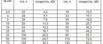
The colors of the wires in the 220 electrics with 3 cores must accurately indicate the phase, working zero and protective ground. There are state standards that allow the use of nine color options to indicate phase and two for neutral and ground.
If a five-wire conductor is used, then the colors according to the requirements are used to mark the zero and ground, and the remaining colors are used for the phase, one of which is usually brown.
Standard colors are used for grounding and neutral, and all others are used to indicate phase. Source magnetic.uz
Designation of colors on electrical diagrams
The number of colors used in the work depends directly on the specific scheme. If the work is carried out according to generally accepted standards, then an experienced electrician will easily understand your network in the future. You don’t have to use additional devices to determine the phase; knowledge of color designation is enough. The standard palette is:
- zero – blue;
- earth – yellow;
- phase – red.
In a single-phase network, one color is used, but if more massive networks are used, the phase can be marked in black and green.
When branching a single-phase network from a three-phase network, the same colors are used.
Before you begin any electrical wiring work, it is important to know the color codes for each wire. Firstly, for the sake of your own safety, and secondly, this approach will provide maximum comfort. Such knowledge simplifies the installation process and future network maintenance. You don't have to use a special screwdriver every time to determine the phase. Experienced electricians will be able to “speak” the same language using color-letter marking standards.
How to determine ground, zero and phase on wires if there are no markings
It is more difficult to determine in practice than in theory. Not all manufacturers comply with the standards. Therefore, when laying a two-phase 220 V network with grounding, you have to use a VVG cable with blue, brown and red colors. Combinations may be different, but without complying with regulatory requirements.
For your information. In old wiring from “Soviet times” there is no color marking. Identical white (gray) shells do not allow the purpose and correspondence of the lines to be known by simple visual inspection.
To avoid problems, it is recommended to carry out installation work using the same type of cable products. When color coding is not available, it should be created at the joints using insulating tape or heat shrink tubing. The latter option is preferable, as it is designed to maintain integrity for a long time.
Below are methods for determining phase and neutral wires with the advantages and disadvantages of each option. In any case, first clarify the network parameters. In old houses, for example, a two-wire connection scheme with a single working and grounding conductor is often used.
The figure shows a modern network with separate grounding and working zero connections. It is possible to connect three- and single-phase loads.
Determining the phase using an indicator screwdriver
Touching the tip of such a device to the phase wire closes the current circuit. This is accompanied by the warning lamp or LED lighting up. A built-in resistor limits the current to a safe level.
Advantages of the indicator:
- minimum cost;
- compactness;
- reliability;
- durability;
- autonomy;
- good protection from adverse external influences.
The disadvantage is the limited measurement accuracy. Under certain conditions, false positives cannot be ruled out.
Determination of ground, zero and phase using a test lamp
To reproduce this technology, you need to prepare a simple design. An incandescent lamp designed for the appropriate mains voltage is screwed into a standard socket. Connect wires of sufficient length to perform work operations in a specific location.
Next, connect one of the wires to the known zero line. Others sequentially check other cable cores. Lighting of the lamp indicates the presence of a phase.
Using a measuring device
When checking a 220 V household network, you do not need to know how to determine the polarity. The power supply is organized using alternating current, so set the multimeter switch to the appropriate position. Touching the phase-zero (phase-ground) wires with the probes is accompanied by an indication of the corresponding voltage (≈220 V). The potential difference between the neutral conductor and ground is minimal.
For your information. When checking an old two-wire circuit, one of the probes touches the reinforcement in a concrete slab, a radiator of a heating system, or another grounded element of a building structure.
When switching to constant voltage, the multimeter will show where the plus and minus are. In the absence of reliable information about the electrical parameters in the circuit, they begin with the maximum measurement range with a sequential transition to smaller values with insufficient accuracy.
Such a “device” is useful for testing DC circuits in the absence of specialized measuring instruments. Bubbles near the negative wire are the release of hydrogen during the electrolysis reaction. The area near the plus will take on a greenish tint after a few minutes.
Using LED
You can create a control device with your own hands by analogy with an indicator screwdriver. Instead of a light bulb, install AL 307 or another LED with similar characteristics. A 100-120 kOhm resistor with a power of 1-2 W is added in series to the circuit.
Wire color marking
For those who deal with electrical wires every day, they know what the colors of the conductor insulation are related to. At the same time, it should be noted that wires are produced that do not have color markings. As a rule, it is more difficult to work with such electrical wires, since you have to use special tools to determine the phase and neutral conductors, as well as grounding.
Marking of wires in a single-phase 220 V network
Considering this type of network, two variations can be distinguished. The first consists of two cores, the second - of three. As you can understand, the main difference between them is the presence or absence of a grounding conductor (PE).
Two-wire wiring is an outdated type and is becoming less common. This design is permitted by GOST and is suitable for premises with low safety requirements. The two-wire TN-C wiring used in older homes had a combined neutral and ground (PEN). Taking into account modern requirements, such a scheme is considered unsafe.
How and with what colors are the wires marked in two-wire single-phase wiring? Let's consider several options:
| (L) | (N) | If you use a solid wire with a brown and blue core, then the first should go to the phase, and the second to the neutral working conductor. This order should not be changed. The only exception is that black, red, gray, purple, pink, white, orange, and turquoise can be used to mark the phase conductor. To be on the safe side, it is recommended to mark the corresponding cores at both ends with tags labeled L (phase) and N (zero). |
| (L) | (PEN) | This circuit has a traditional brown conductor as a phase conductor (L). As in the previous case, the brown coating can be replaced with one of the acceptable colors. The three-color (yellow, green, blue) conductor (PEN) is used simultaneously as a zero working (N) and a zero protective (PE). Despite the combination of N and PE, in fact, the end user does not have grounding. |
Starting from the seventh edition of the PUE (electrical installation rules), electrical wiring in an apartment or house must be carried out with a three-core cable with copper conductors (three-wire circuit).
Let's look at which conductors are included in a three-wire circuit and how they are marked:
| Phase L (from English Live - live) is a working wire under high voltage. | The main color of the core is brown (possibly a brown stripe on a white background) |
| Acceptable core color: black, red, gray, purple, pink, white, orange, turquoise. | |
| Neutral (working zero) N (from English Neutral) is a voltage-free auxiliary conductor through which load current flows in operating condition. | The main color of the core is blue, light blue (possibly a blue stripe on a white background) |
| Earth (protective zero) PE (from English Protective Earth - protective earth) is a separate unloaded conductor for grounding. Under normal conditions, no current flows through the protective zero. | The main color of the core is yellow and green stripes (possibly a green stripe on a yellow background). |
Additional marking of wires
If the purchased cable has conductors of a color that does not comply with the standards, or the wiring has already been laid and is incorrectly marked, additional identification must be carried out.
Additional marking of wires.
During the electrical installation process, the ends of the wires are marked using heat-shrinkable tubing or colored insulating tape. Additionally, the letter designation of the cores can be applied to the wire or a tag attached to the wire:
- L – phase.
- N – neutral (working zero).
- PE – ground (protective grounding).
Ground color
The color of the grounding wire, “ground”, is almost always indicated by yellow-green color
. Windings that are either completely yellow or light green are less common. The wire may be marked “PE”. You can also find green-yellow wires marked “PEN” and with blue braiding at the ends of the wire at the fastening points - this is grounding combined with neutral.
In the distribution panel (DP) it should be connected to the grounding bus, to the housing and the metal door of the panel. As for the distribution box, the connection goes to the grounding wires from the lamps and from the grounding contacts of the sockets. The ground wire does not need to be connected to the RCD (residual current device), therefore RCDs are installed in houses and apartments, since electrical wiring is usually carried out with only two wires
Grounding designation on the diagrams:
Conventional ground(1) Clean ground(2) Safety ground(3) Chassis ground(4) DC ground(5)
What is the difference between grounding
Wire Definition
Sometimes situations arise when it is necessary to determine the purpose of a particular wire if there is no marking on it. The simplest and most common way is to use an indicator screwdriver. With its help, you can accurately determine which wire will be phase and which will be neutral. First of all, you need to turn off the power supply to the panel. After this, the ends of the two conductors are stripped and separated to the sides away from each other. Then you need to turn on the electricity supply and use the indicator to determine the purpose of each wire. If the light bulb lights up upon contact with the core, this is a phase. This means the other core will be neutral.
If there is a ground wire in the electrical wiring, it is recommended to use a multimeter. This device is equipped with two tentacles. First, the measurement of alternating current in the range of more than 220 volts is set at the appropriate mark. One tentacle is fixed at the end of the phase wire, and the second one determines grounding or zero. In case of contact with zero, the device display will display a voltage of 220 volts. When you touch the ground wire, the voltage will be noticeably lower.
Color of zero, neutral
The “zero” wire should be blue
. In the distribution board it must be connected to the zero bus, which is designated by the Latin letter N. All blue wires must be connected to it. The bus is connected to the input via a meter or directly, without additional installation of the machine. In the distribution box, all wires (except for the wire from the switch) of blue color (neutral) are connected and do not participate in switching. To the sockets, the blue “zero” wires are connected to the contact, which is designated by the letter N, which is marked on the back of the sockets.
The designation of the phase wire is not so clear. It can be either brown, or black, or red, or other colors except
blue, green and yellow. In an apartment switchboard, the phase wire coming from the load consumer is connected to the lower contact of the circuit breaker or to the RCD. In switches, the phase wire is switched; during switching off, the contact closes and voltage is supplied to consumers. In phase sockets, the black wire must be connected to the contact marked with the letter L.
How to find ground, neutral and phase in the absence of a designation
If there is no color marking of the wires, then you can use an indicator screwdriver to determine the phase; upon contact with it, the screwdriver indicator will light up, but not on the neutral and ground wires.
You can use a multimeter to find ground and neutral. We find the phase with a screwdriver, fix one contact of the multimeter on it and “probe” the wires with another contact; if the multimeter shows 220 volts, this is neutral; if the values are below 220, then it is grounding.
Letter and numeric wire markings
The first letter “A” denotes aluminum as the core material; in the absence of this letter, the core is copper.
The letters “AA” denote a multi-core cable with an aluminum core and an additional braid made of it.
"AC" is indicated in case of additional lead braiding.
The letter “B” is present if the cable is waterproof and has an additional double-layer steel braid.
“BN” cable braid does not support combustion.
"B" polyvinyl chloride shell.
"G" does not have a protective shell.
“g” (lowercase) bare, waterproof.
“K” is a control cable wrapped with wire under the top sheath.
"R" rubber casing.
"NR" non-flammable rubber casing.