Selection of current transformers for a 0.4 kV electric meter
Electricity metering with a current consumption of more than 100A is carried out by transformer connection meters, which are connected to the measured load through measuring transformers. Let's consider the main characteristics of current transformers.
1 Rated current transformer voltage.
In our case, the measuring transformer should be 0.66 kV.
2 Accuracy class.
The accuracy class of measuring current transformers is determined by the purpose of the electric meter. For commercial accounting, the accuracy class must be 0.5S; for technical accounting, 1.0 is allowed.
3 Rated current of the secondary winding.
4 Rated current of the primary winding.
This parameter is the most important for designers. Now we will consider the requirements for choosing the rated current of the primary winding of an instrument transformer. The rated current of the primary winding determines the transformation ratio.
The transformation ratio of an instrument transformer is the ratio of the rated current of the primary winding to the rated current of the secondary winding.
The transformation ratio should be selected according to the design load, taking into account operation in emergency mode. According to the PUE, the use of current transformers with an increased transformation ratio is allowed:
1.5.17. It is allowed to use current transformers with an increased transformation ratio (according to the conditions of electrodynamic and thermal resistance or busbar protection), if at the maximum load of the connection the current in the secondary winding of the current transformer is at least 40% of the rated current of the meter, and at a minimum operating load - at least 5 %.
In the literature you can also find requirements for the selection of current transformers. So, a current transformer should be considered overestimated in terms of transformation ratio if, at 25% of the calculated connected load (in normal mode), the current in the secondary winding will be less than 10% of the rated current of the meter.
Now let’s remember the mathematics and look at these requirements using an example.
Let the electrical installation consume a current of 140A (minimum load 14A). Let's choose a measuring current transformer for the meter.
Let's check the measuring transformer T-066 200/5. Its transformation coefficient is 40.
140/40=3.5A – secondary winding current at rated current.
5*40/100=2A – minimum current of the secondary winding at rated load.
As you can see 3.5A>2A – the requirement is met.
14/40=0.35A – secondary winding current at minimum current.
5*5/100=0.25A – minimum secondary winding current at minimum load.
As you can see 0.35A>0.25A – the requirement is met.
140*25/100 – 35A current at 25% load.
35/40=0.875 – current in the secondary load at 25% load.
5*10/100=0.5A – minimum secondary winding current at 25% load.
As you can see, 0.875A>0.5A – the requirement is met.
Conclusion: the T-066 200/5 measuring transformer for a 140A load is selected correctly.
For current transformers, there is also GOST 7746-2001 (Current Transformers. General Technical Conditions), where you can find the classification, main parameters and technical requirements.
When choosing current transformers, you can be guided by the data in the table:
Selection of current transformers by load
Please note that there are typos there
Source
Selection of current transformers
We start choosing by type of installation. Why do you need a current transformer:
- for work in enclosed spaces
- for outdoor work
- for installation in cavities of electrical equipment
- for special installations
and then select by installation method:
- checkpoints
- supporting
- built-in
and according to other conditions by which current transformers are classified.
It’s really easy to choose because you already know where and how you will install the current transformer.
Of course, we do not forget what the current transformer is intended for: for measurements, or for use in protection devices. And besides, if for measurements, then what will be the accounting?
If it is commercial, then current transformers for connecting meters for which cash payments are made will have to have an accuracy class of at least 0.5. For various types of technical accounting, it is allowed to use current transformers of accuracy class 1, for connecting indicating ammeters - accuracy class not lower than 3. If a current transformer is intended for operation in relay protection devices, it must have a special accuracy class, designated 10(P).
Selection of CT by rated voltage
The rated voltage of the selected CT must not be lower than the maximum operating voltage: Unom ≥ Uset
Selection of CT by rated primary current
The rated primary current of the selected CT must not be lower than the maximum operating current of the installation: I1nom ≥ Ioper.max
After this, it is necessary to carry out a verification calculation on the electrodynamic and thermal resistance of the current transformer to short-circuit currents.
Selection of current transformers by load
Next, check the permissible load of the secondary circuit. To ensure that the previously mentioned error of the selected current transformer does not exceed the permissible value for a given accuracy class, the secondary load of the CT Z2p should not exceed the rated Z2nom indicated in the product passports.
The reactance of current circuits is small, so they take Z2р=R2р. Then the secondary load has the form: R2= Rprib+Rpr+Rk where Rpr is the total resistance of the devices, Rpr is the resistance of the connecting wires, Rk is the contact resistance.
To determine the resistance of devices powered by current transformers, it is necessary to determine the total power of electrical measuring instruments installed in this connection. We find the total resistance of the devices as:
Rarrib = S2 / I22nom,
where: S2 - total power consumed by devices, VA; I2nom - rated current of the secondary winding of the transformer, A.
I almost forgot about the transformation ratio - choose - which one do you need?
Selection of current transformers for connecting meter meters
To correctly select current transformers (CTs) for rated meters, we need to correctly select the transformation ratio of the current transformer, based on the fact that the estimated load of the connection will operate in emergency mode.
The transformation ratio is considered overestimated if, at a 25% connection load in normal mode, the current in the secondary winding will be less than 10% of the rated current of the connected meter - 5 A.
In order for the connected devices to operate in the required accuracy class (I remind you that for commercial metering meters the accuracy class of current transformers must be - 0.2; 0.2S; for technical metering - 0.5; 0.5S), it is necessary that, the connected secondary load Zн did not exceed the rated secondary load of the current transformer for a given accuracy class, and the condition Zн ≤ Zadd must be met. This is discussed in detail in the article: “Selection of current transformers for voltage 6(10) kV.”
Another condition for the correct selection of current transformers is checking the current transformers for current ΔI and angular error δ.
The angular error is taken into account only in the readings of meters and wattmeters, and is determined by the angle δ between the vectors I1 and I2.
The current error is determined by the formula [L1, p61]:
- Knom. – transformation ratio;
- I1 – current of the primary winding of the CT;
- I2 – current of the secondary winding of the CT;
Current transformers for meters: operating principle and purpose
The task of the CT is to protect the power system from damage. The design of electricity meters is designed for operation in specific conditions. The current and voltage characteristics are indicated in the manufacturer's passport. Exceeding the permissible values causes a short circuit and burnout. In installations with current transformers, secondary measuring lines are separated from the primary consumer circuits. The load on the metering unit is reduced to the required values. Small values are safe. Repairs are completed faster. It is easier to replace a compact current transformer than a meter.
CTs are converters of high current loads to low ones. Each brand has its own transformation level K. The coefficient shows how many times the secondary current is less than the primary. Electricity consumption is defined as the difference between readings multiplied by K. Models with a multiplicity of 10/5 to 100/5 are popular. The formula 100/5 means that the device is ready to convert the power supply load equal to 100A into the 5 Amps required for the meter to operate.
The installation characteristics of the structure contribute to full operation.
- The electrical alloy core has low magnetic resistance.
- Insulated windings are resistant to overheating. Material – copper, aluminum. The type of primary winding influences the method of installation of devices: coil, busbar, rod, single-turn, multi-turn.
- The terminals on the inputs and outputs of the windings are marked at the manufacturer. The quality of fastener tightening affects the accuracy of the readings.
- The casing protects the elements.
- Small size, weight. The device fits into an apartment panel.
- Service life – 25 years.
The action is based on electromagnetic induction. The primary winding is connected to the power section, the secondary winding is connected to the coil of a three-phase meter. The phase current creates magnetic waves in a closed circuit of the core. Under the influence of the driving force of the particles, electricity appears in the secondary winding. The signal reaches the accounting node.
The primary winding is connected in series, the secondary winding is connected to the load. Consumer and measurement indicators are proportional to each other.
Converters are more often found on 3-phase lines. Most single-phase devices are installed directly into the network. The recommended load for direct connection is 60 Amperes.
An example of selecting a current transformer for installing metering meters
It is necessary to select current transformers for the outgoing line feeding the TM-2500/6 transformer. The calculated current in normal mode is 240.8A, in emergency mode, when the transformer is overloaded by 1.2, the current will be 289A.
We choose a CT with a transformation ratio of 300/5.
1. Calculate the primary current at 25% load:
2. Calculate the secondary current at 25% load:
As you can see, the current transformers are selected correctly, since the following condition is met:
I2 > 10%*In counter, i.e. 1 > 0.5.
When choosing current transformers for metering meters, I recommend using tables II.4 – II.5.
Table II.5 Technical data of current transformers
Table II.4 Selection of current transformers
| Maximum rated power, kVA | Voltage | |||
| 380 V | 10.5 kV | |||
| Load, A | Transformation coefficient, A | Load, A | Transformation coefficient, A | |
| 10 | 16 | 20/5 | — | — |
| 15 | 23 | 30/5 | — | — |
| 20 | 30 | 30/5 | — | — |
| 25 | 38 | 40/5 | — | — |
| 30 | 46 | 50/5 | — | — |
| 35 | 53 | 50/5 (75/5) | — | — |
| 40 | 61 | 75/5 | — | — |
| 50 | 77 | 75/5 (100/5) | — | — |
| 60 | 91 | 100/5 | — | — |
| 70 | 106 | 100/5 (150/5) | — | — |
| 80 | 122 | 150/5 | — | — |
| 90 | 137 | 150/5 | — | — |
| 100 | 152 | 150/5 | 6 | 10/5 |
| 125 | 190 | 200/5 | — | — |
| 150 | 228 | 300/5 | — | — |
| 160 | 242 | 300/5 | 9 | 10/5 |
| 180 | — | — | 10 | 10/5 (15/5) |
| 200 | 304 | 300/5 | — | — |
| 240 | 365 | 400/5 | 13 | 15/5 |
| 250 | — | — | 14 | 15/5 |
| 300 | 456 | 600/5 | — | — |
| 320 | 487 | 600/5 | 19 | 20/5 |
| 400 | 609 | 600/5 | 23 | 30/5 |
| 560 | 853 | 1000/5 | 32 | 40/5 |
| 630 | 960 | 1000/5 | 36 | 40/5 |
| 750 | 1140 | 1500/5 | 43 | 50/5 |
| 1000 | 1520 | 1500/5 | 58 | 75/5 |
Considering the need to connect current transformers to power measuring instruments and relays, which require different accuracy classes, high-voltage current transformers are made with two secondary windings.
1. Handbook for calculating electrical networks. I.F. Shapovalov. 1974
Source
What are current transformers used for?
For energy meters and other measuring instruments, connection to a high-voltage line is fraught with complication of the design (accordingly, the cost of the device can increase significantly). The situation is similar with other control devices and safety devices. It is necessary to ensure decoupling between the high-voltage line and parameters acceptable for operation. Based on this, the purpose of the current transformer is as follows:
- By calculating the proportions of operating parameters on the secondary winding, engineers obtain a measurement coefficient. The secondary connects to any measuring instruments: ammeters, wattmeters, electricity meters, etc. Low-value alternating current is convenient to use, does not pose a danger to personnel, and is measured with conventional instruments without expensive protection systems. Given their compactness, the transformers are easily mounted in a standard distribution panel.
- Another function of a current transformer is to ensure the operation of control and protection systems. To display information about the state of electrical circuits, a small signal level is sufficient. The enormous voltage values on the power lines do not allow connecting control circuits to them. Therefore, relay protection and control components are connected to the secondary windings of transformers, and operate on lines of tens of thousands of volts, as if it were a household input panel in an apartment. Of course, safety is also top notch.
We will consider the main task of the device: connecting the meter through current transformers. Since single-phase systems operate without high voltage potentials, current transformers most often provide operation of a three-phase meter.
Description and principle of operation
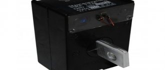
Current transformer is an electromagnetic converting device, structurally consisting of:
- one-piece magnetic circuit;
- two windings, necessarily isolated from each other and from the ground (primary and secondary);
- plastic sealed non-separable case;
- contact terminals for connecting a measuring device;
- fastening elements for mounting the device;
- plate on the case, paper passport.
The windings of the converter are divided among themselves into primary and secondary, and are included in the energy circuit strictly according to certain rules.
The primary winding is connected to the electrical circuit in series (cutting the conductor). The secondary winding is closed to a certain load of measuring elements, relay equipment and automation. It passes through itself an amount of current that is proportional to the current value of the primary winding.
The operating principle of any of them is based on the law of electromagnetic induction, which operates equally in the electric and magnetic fields of electrical machines and mechanisms.
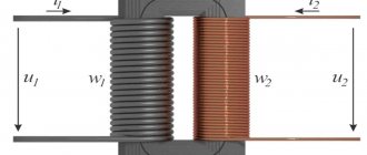
Its essence is the conversion of the amount of current flowing through the power circuit of the power plant, to which the primary winding of a current transformer with a certain number of turns is connected, into a secondary reduced current value, while maintaining the proportionality of the value.
This proportional amount of electric current at the output terminals of the secondary winding of the transformer is necessary for the normal operation of measuring, relay equipment, and electricity metering devices in power energy systems up to and above 1000 volts.
There is a direct dependence of the nominal operation of all measuring systems, monitoring and control devices on the correct choice of current transformers.
Connecting the meter via current transformers
What features of connecting a meter through current transformers should you be aware of?
The purpose of electric meters is well known to any person, even if they are terribly far from the electricity sector. Meters are used to keep track of the electricity consumed in AC power networks with a 50 Hz frequency. They are connected to 3 or 4-wire electrical networks using current measuring transformers of 5 amperes and 100 volts.
The greatest interest among electricity consumers is most often caused by questions of the correct and competent connection of meters through current transformers to electrical networks, since without this it is impossible to properly organize an efficient power supply system at any facility, regardless of its purpose. It is worth emphasizing that in this particular case it is absolutely not important what type of meter is used - induction or electronic, the main thing is what is the most optimal circuit that needs to be selected to make such a connection to electricity.
Another extremely important issue that requires serious attention is maintaining the polarity of the primary and secondary windings of the current transformer, their beginning and end, as well as the polarity of the windings itself with the polarity of the transformer.
Before proceeding directly to connecting the electric meter, you should pay attention to a number of the following points. A diagram of the correct connection of an electric meter is almost always depicted on its cover along with markings and information about the output. Plus, such a process is always described in detail in the product data sheet attached to the device. In any case, it is better to have information in advance about such issues as the location of installation of the meter, its type and the intended connection diagram in each specific case.
It is also necessary to take into account the fact that all electrical installation work must be organized only in accordance with the PUE, and no exceptions are allowed. The wire must, of course, be copper with a cross-section of 2.5 square meters. mm (this is for current circuits) and 1.5 sq. mm (for voltage circuits). Finally, it should be noted that to facilitate the use and maintenance of the electric meter in the future, it makes sense to use colored wires when installing and connecting.
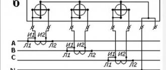
Several options for connecting a three-phase meter with current transformers
Option #1.
This diagram represents the organization of connecting an electric meter to a 3-wire network, consisting of three phases, the number of current transformers is 2.
Option number 2.
This version of the connection diagram for a three-phase meter with current transformers includes the organization of connecting an electric meter to a 3-wire network consisting of three phases, the number of current transformers is 3.
Option number 3.
Finally, the third version of the circuit involves connecting an electric meter to a 3-wire network consisting of three phases, the number of current transformers is 2, the number of voltage transformers is 2.
Below you can use the online calculator to calculate the cost of electrical installation work.
Contents
show
1. Online calculation of design costs 1.1. Electric installation work
2. Submit an application for the selected
Online design cost calculation
Classification
Converters, in addition to the areas of operation described above, are usually classified according to their main characteristics, knowledge of which is necessary for their correct selection in various power electrical installations.
Series transformers are usually classified according to:
By type of installation
The class of current measuring devices is divided into several options for general or special purposes:
- Portable – special-purpose transformers used for control measurements or tests in mobile electrical laboratories;
- Overhead – special-purpose conversion devices used in high-voltage installations by placing the bushing insulators of the network power transformer circuits on top;
- Built-in – special type instrument transformers used inside various electrical devices and machines to convert values of the internal circuit of the equipment;
- Indoor installation – general-purpose electrical devices used on high-voltage electrical distribution systems, or low-voltage power circuits (400V);
- Outdoor installation – general-purpose conversion devices used in open high-voltage distribution networks (over 1000V).
Precise determination of the equipment in the circuit section to which serial converters will be connected becomes one of the important criteria for their selection.
By installation method
The type differences in the housings of series transformers of the electrical network divide them by installation class into:
- Feedthroughs - play the role of a feedthrough insulator through a certain obstacle in the electrical installation system. The leads of their primary windings are always located at the top, the other at the bottom;
- Support - structurally have all primary terminals located on one side. They are always installed on a flat supporting surface.
Correctly determining the type of installation of a measuring device for current conversion will prevent errors in the further design of a new energy system or repair of an already created installation.
By type of insulation
Groups of conversion measuring instruments have differences in the composition of the insulation material of their windings and housings, and are divided into several main ones:
- Solid - type of dry insulation in the form of porcelain, bakelite and similar materials;
- Viscous - insulation obtained by pouring with various compounds.
- Mixed - the use of paper-oil elements as an insulating material;
- Gas - the primary winding is isolated from the secondary winding by an air gap.
The insulating material of the equipment is selected depending on the type of electrical installation where it is used. It also depends on the rated voltage at the installation site of the devices, the climatic conditions where the switchgear will be operated and other factors.
By the number of transformation steps
Transformers are divided into two main types in this classification section:
- Single-stage - such devices have one primary and one secondary winding in the device, one unchangeable transformation ratio;
- Multistage - electromagnetic devices of a cascade type, the device of which contains either the ability to change the number of turns of the primary or secondary winding, or contains several secondary windings with a trim of their number of turns. This design allows you to have multiple transformation ratios in one device;
The first class of transformers is the most common in the use of general-purpose power plants. The second type is used in specialized areas of distribution networks as needed.
By the number of secondary windings
Accordingly, based on the number of transformation stages, devices are divided into:
- With one secondary winding;
- With two or more secondary windings.
The main type of transformers in this division classifies the first type as a general-purpose device, and the second as a special-purpose type.
By purpose
The main purpose of this electromagnetic device is to transform current from one value to another. There are two main directions for using transformers:
- For measurements – transfer of measuring parameters to instruments, the readings of which are taken by electrical installation personnel in order to analyze the operation of high-voltage power plants (>1000V). The primary winding of the current transformer is connected to a break in the energy circuit, and the required measuring device, such as an ammeter, wattmeter windings or electricity meters, is connected to its secondary winding. Their installation is carried out in power installations where direct connection of measuring equipment and electric meter windings directly is impossible, but their normal functioning is necessary.
- For protection – transfer of measurement information to protection devices, or any control modules of the energy system in which they are included. Ensures isolated operation of these devices in high-voltage installations or power circuits with a voltage of 400V. Isolation of relays and control devices from the primary circuit of the installation ensures safe accessibility to such modules by maintenance personnel for their repair and operation.
Current transformers for electric meters - characteristics and connection options
When operating energy systems of various types, situations often arise that require converting electrical quantities into analogues with certain ratios.
Current transformers for electric meters can significantly expand the standard measurement limits of metering devices.
Current transformer rated voltage
One of the main parameters related to current transformers for electric meters is the rated voltage level, which is indicated in the passport for the device. Voltage ratings range from 0.66kW to 1150kW:
- 0.66 kW;
- 6.0 kW;
- 10 kW;
- 15 kW;
- 20 kW;
- 24 kW;
- 27 kW;
- 35 kW;
- 110 kW;
- 150 kW;
- 220 kW;
- 330 kW;
- 500 kW;
- 750 kW;
- 1150 kW.
The rated values of the primary current level on an electrical circuit indicate the current indicators on the primary transformer winding.
The secondary rated current parameters are the standard values on the secondary type winding. The determination of such current flows is carried out based on the nominal values of power and voltage.
In this case, the primary type of winding is connected to a source of electrical energy, and the secondary winding is closed to measuring or protective type devices with low internal resistance.
The current parameters of the rated or line voltage, under the conditions under which the instrument current transformer remains operational, must be indicated in the accompanying documentation and reflected in the table for the device.
Accuracy class
With the correct choice of current transformer device, the consumer has a real opportunity to connect measuring and protective devices to high-voltage electrical lines. The accuracy class level is one of the most important characteristics indicating the measurement error, which should not be higher than the parameters according to regulatory documents.
The accuracy class is determined by several main factors, including current and angle errors, as well as relative total error indicators. The first two concepts are always characterized by magnetizing current.
Operating principle of current transformer
Industrial devices use several accuracy classes:
In accordance with the GOST currently in force in our country, the accuracy class should be focused on current errors, therefore for indicators of ±40′ class 0.5 is assumed, and for ±80′ – class 1.0. It should be noted that classes 3.0 and 10P are not standardized according to existing rules.
The presence of the letter “S” in the marking indicates an accuracy class within the range of 0.01-1.2.
Class 10P is used in protective circuits, and standardization is carried out in accordance with the relative total error of no more than ten percent.
The use of devices with an accuracy class of 1.0 is allowed, but only if the electric meter has an accuracy class of two units.
The measuring and information system, represented by devices that receive, process and transmit data, as well as metering devices, is capable of generating correct indicators only with high accuracy of current transformers.
For commercial accounting, the accuracy class level should be 0.5S, and for technical accounting – 1.0S.
Rated secondary current
The structure of the secondary winding of current transformers, which are designed for voltages of no more than a thousand volts, has some differences. At least two secondary windings are installed on a high-voltage device.
The principle of their operation is similar to the functioning of a step-up transformer. Regardless of the power level of the primary winding, the current rating on the secondary winding is usually stable at 5A.
Current transformer design
The rated values of the secondary current “I2n” are indicated in the table attached to the device passport. The rated currents on the secondary winding are equal to unity or 5A, but the second indicators are allowed only in devices with primary currents not exceeding 4000A.
However, it is also possible to manufacture modern current transformer devices on individual orders with secondary current ratings of 2.0A or 2.5A.
Rated primary current
Depending on the design features of the primary winding, current transformers can be not only multi-turn, but also single-turn and busbar.
Today, the second version of the device is most widespread.
Single-turn models of current transformers are represented by varieties that do not have an individual primary winding or with an individual primary winding.
Single-turn models without their own primary winding are characterized by a built-in, busbar or detachable design. The primary current level, in this case, is always determined in accordance with the standardized rated currents.
Rated currents of the primary type “I1н” are indicated in the passport tabular data of the transformer device, and determine the standard transformation ratios in the form of the ratio of the rated current indicators on two types of windings of the device.
It is necessary to select the transformation ratio in strict accordance with the design load, as well as with mandatory consideration of the possibility of functioning of the installed device in emergency situations. The current rating on the primary winding cannot be less than the maximum operating current values of the operated electrical installation: I2nom.tt>Imax.eu.
It is allowed to use devices that have overestimated coefficient values, provided that the maximum load level of the current connection on the secondary winding is 40% or more of the rated current of the electric meter. Minimum workload requirements are 5% or more.
Connection diagram
Let's look at how to connect a current transformer. Depending on the design features of the current transformer for electric meters, there are several types of such devices:
- current transformers intended for outdoor installation in outdoor switchgear;
- current transformers intended for closed installation of distribution devices;
- built-in current transformers;
- current transformers intended for installation on bushing-type insulators;
- current transformers in portable or mobile design.
Current transformers provide complete insulation of the operated power electrical circuits. A measuring device in everyday life is a guarantee of safe operation, so experts recommend using the so-called galvanic isolation. The disadvantages of this installation method include a fairly large number of electrical wires.
The connection of the electric energy meter through current transformers is carried out using ten-core cables. The design uses separate circuits for both current and voltage. The standard installation diagram requires the mandatory connection of three elements of the electric meter in compliance with the polarity rules with direct phase rotation relative to “U”.
Electric meter connection diagram via current transformers
In the process of self-installation of electrical energy measuring instruments, current transformers are connected to circuit breaks using special, very easy-to-use clamps “L-1” and “L-2”.
Video on the topic
How to choose
The choice of current transformers (CTs) depends not only on knowledge of their classification in a general format, but also requires a correct assessment of many other transformer quantities. In electrical engineering, such values are usually called nominal parameters.
Ratings
The correct choice of CT consists of selecting your own nominal values, conducting test checks, the results of which will become fundamental for determining the required brand of transformers.
The main nominal parameters of the CT consist of:
Operating voltage
The value of the operating voltage - that is, the value of the effective voltage of the distribution installation where a certain instrument transformer is selected must be less than or equal to the rated voltage of the transformer. For effective selection, there is a standard range of operating voltage ratings, expressed in kilovolts: 0.66, 3, 6, 10, 15, 20, 24, 27, 35, 110, 150, 220, 330, 750.
CT primary current
The second main parameter for choosing a measuring device occurs in almost the same way as selecting the operating voltage: tabulated current standards of CT currents are compared with the value of the operating current of the circuit section or the entire electrical installation where the converter device is planned to be installed.
However, here one more criterion must be taken into account: in a network with active loads and general-purpose consumers, the ratings are selected without taking into account correction current margins, but for electrical equipment of generators, engines or other active-reactive consumers, it is necessary to take into account a 10% margin when choosing the primary CT current its size. This is due to surges in current values at the time of startup of such equipment.
The standard values by which the current of the primary winding of the transformer is selected are enclosed in a certain table row, the units of measurement are amperes: 1, 5, 10, 15, 20, 30, 40, 50, 75, 80, 100, 150, 200, 300, 400 , 500, 600, 750, 800, 1000, 1200, 1500, 1600, 2000, 3000, 4000, 5000, 6000, 8000, 10000, 12000, 14000, 16000, 18000, 20000, 25000, 28000, 30000, 32000, 35000 , 40000.
If the choice of primary current, taking into account the 10% margin, is between the standard values of the series, the larger of their values is taken.
However, here it is necessary to obtain data from two more mandatory tests of transformers in order to be completely sure of its correct choice:
Thermal resistance test
Thermal resistance ensures that the selected CT can withstand thermal shock and remain in normal operating condition, without any damage, in an emergency short circuit (SC) condition when a certain amount of short circuit current passes through it over a certain period of time. There is a special formula for test values for the thermal resistance of converter devices up to and above 1000 V.
If the selected transformer does not meet the calculated thermal resistance values, you should pay attention to another transformer model in order to avoid problems with the power plant during its further operation.
For electrodynamic resistance
This experimental-calculation process tests the selected transformer for resistance to the dynamic impact of short-circuit current on it during emergency operation in the circuit. An electromagnetic device must withstand such an impact for a certain period of time and remain in working condition.
Otherwise, a change in the brand or model of the transformer is required. The electrodynamic resistance test is determined by a special formula, which involves constant values and emergency mode values.
Secondary load power test
The third mandatory parameter for selecting a CT. The test is carried out by comparative analysis of the rated power of the CT and the total power of the secondary load over the entire section of the circuit in which the selected current transformer is planned to be installed. The power rating must be greater than or equal to the value in the existing or planned installation.
It is important to know that the total load power of the circuit is the sum of the resistances of all switching, measuring, relay devices and control equipment of the section multiplied by the square of the current of this equipment.
If the selection is carried out in the switchgear being designed, the resistance values are taken from the passport data of the equipment installed there; if the object is already operating, the resistance values are obtained by measuring the resistance of ohmmeters or other known methods.
Key parameters of instrument transformers
Operating principle of a current transformer
The rated voltage determines the circuits in which the transformer can operate. There are two large groups: up to 1 kV and above. Converters of the 0.66 kV class are common in everyday life.
Transformation ratio is the ratio of the rated primary and secondary currents. At the input, the values vary depending on the parameters of the supply network: 1, 2, 5, 10, 15, 20, 30, 40, 50, 75, 80, 100, 150, 200, 300, 400, 500, 600, 750, 800 , 1000, 1200, 1500, 1600, 2000, 3000, 4000, 5000, 6000. At the output, it is unified to the scale of measuring instruments 1, 2, 5. The marking with the designation looks like a fraction (50/5, 100/5, 200/ 5, etc.).
The accuracy class indicates the maximum permissible error in energy metering as a percentage. The most accurate instruments are used for commercial purposes:
- 0.2s;
- 0.5s.
The symbol s indicates that accounting is possible within the minimum division.
For other models this is a blind spot. In measuring circuits of different directions:
- 0,1;
- 0,2;
- 0,5;
- 1;
- 3.
Relay protection: 10R.
If the number of windings is more than one, the accuracy class for each is determined separately. Up to 1000 V, it is customary to connect simple CTs in series, but above 1000 V this is expensive, so one converter with several windings is installed. For example, the first may be for the protection circuit - 10P, the second - 0.5, the third - 0.5s.
If the rated load power specified in the characteristics of the transformer is not observed (5 VA, 10 VA, 15 VA, 30 VA, etc.), the accuracy class drops relative to the declared one.
Connection schemes
To power relay equipment, current windings for electricity metering for general or commercial purposes, there are three main circuits for connecting current transformers:
Each type of connection for various purposes optimizes the operation of measuring and metering systems of electrical equipment, and makes it possible to optimize the parameters of electricity metering in the circuits of new or existing distribution devices up to and above 1000 volts.
METER CONNECTION DIAGRAMS
RICE. 8
. INCLUDING A SINGLE-PHASE METER DIRECTLY INTO THE 022 kV NETWORK
RICE. 9. TURN ON
READING THE ACTIVE ENERGY METER DIRECTLY INTO THE 0.4 kV NETWORK
Rice. 10.
CONNECTION OF AN ACTIVE ENERGY METER THROUGH CURRENT TRANSFORMERS INTO A 0.4 kV NETWORK
RICE. eleven.
switching on a two-tariff electricity meter type SEB-2
Note. In a single-tariff meter, clamp 14 is missing, and tariff P control lines are not connected.
RICE. 12
. DIRECT: TURNING ON THE THREE-PHASE TWO-TARIFF METER SETC-2
RICE. 13
. ACTIVATION OF THREE-PHASE DV9KhTARIFF METER SETC-2 WITH CURRENT TRANSFORMERS
A) DIRECT ACTIVATION:
B) TRANSFORMER CONNECTION
RICE. 14
. INCLUSION OF THREE-PHASE METERS OF TYPE PSC, PSC-ZM, PSC-ZT INTO THE 0.4 kV NETWORK
THREE-PHASE METER PSCH-3
THREE-PHASE METER PSCH-3M
THREE-PHASE TWO-TARIFF METER PSCH-ZT
RICE. 15.
INCLUSION OF THREE-PHASE METERS OF TYPE PSCH-3, PSCH-3N, PSCH-3T INTO THE INFORMATION NETWORK
RICE. 16
. DIAGRAM FOR CONNECTING AN ACTIVE METER IN A FOUR-WIRE NETWORK WITH A TEST (ADAPTER) BOX
How to choose the right CT for relay protection
In order to correctly select current transformers for various relay protection and automation units, you should pay attention to several important parameters for their selection:
- The maximum and nominal voltage value in the primary winding of the transformer;
- Rated value of current in the primary winding;
- Accuracy class.
The last parameter has different values for different types of transformers, but for relay protection and automation units it has priority due to the fact that the accuracy of the output signal depends on it, in other words, the quality of power supply of the entire protection and automation unit. For more accurate operation of protection and automation systems in distribution networks, the use of transformers with an increased accuracy class of 10 (P) is used. A detailed discussion of the concept of accuracy class in the article is published below.
Type of devices
When choosing a transformer, you need to take into account its location (closed or open distribution installations, embedded systems), as well as design features (feed-through, busbar, support, detachable).
The bushing CT is installed in complex switchgear and used as a bushing insulator. Supporting ones are used for installation on a flat surface. The busbar CT is installed directly on live parts. The bus section acts as the primary winding of the transformer. Built-in models as a structural element are installed in power transformers, oil switches, etc. Detachable CTs are made dismountable for quick installation on cable cores, without physical interference with the integrity of electrical networks.
In addition, the division also takes place according to the type of insulation used:
- cast;
- plastic case;
- hard;
- viscous compound;
- oil-filled;
- gas-filled;
- mixed oil-paper.
And they are distinguished by specification and scope of application:
- commercial accounting and measurements;
- protection of power supply systems;
- measurements of current parameters;
- control and recording of current values;
Transformers also differ in voltage: for electrical installations up to 1000 Volts and above.
Selection of accuracy class
Current transformer parameter indicating that the measurement error of the current value of the secondary winding of the CT does not exceed the values specified in regulatory documents in accordance with GOST 7746-2011. According to this GOST, the nominal values of accuracy classes are as follows: 0.1, 0.2S, 0.2, 0.5, 0.5S, 1, 3, 5, 10.
For circuits of measuring instruments, metering equipment and relay protection systems, the accuracy classes of current converters will be different.
And for electricity metering of a general or commercial type, the usual accuracy classes of current converters are used equal to 1, 3. It should be added that to power measuring instruments such as ammeters and the like, current transformers with an accuracy class of 0.5 or increased accuracy are selected, the error of which is 0. 5S.
Automation and relay protection units require the use of high-precision equipment for their power sources in distribution networks, in which the error in the current value of the secondary winding of the transformer will not exceed 10% of the value. The marking of this accuracy class is 10 (P).
Replacing electric meters – Electrics – Some tips
Home / Some tips / Electrics / Replacing electric meters
An electric meter is a device that keeps track of electricity consumed at home and in industrial enterprises. Today the market offers a wide selection of different counters, in order to choose the right one, you need to understand what they are.
Meters are divided by type of operation into induction and electronic. Induction meters are a cheaper option, while electronic ones are more reliable and accurate. There are also single-phase and three-phase meters for various networks.
The accuracy class of electricity meters is divided from 0.2 to 2.5. This figure shows the level of instrument error. Not long ago, a new GOST was introduced, according to which devices with an accuracy class of at least 2 percent can be used in everyday life.
note
Whereas previously a measurement error of 2.5 was allowed. Depending on the connection, electricity meters can be directly connected or connected via transformers. If the total load does not exceed 100 amperes, a direct connection meter can be used.
For larger loads, it should be connected via a current transformer.
There are 2 voltage classes: 220/380 V and 100 V.
There are single-tariff, double-tariff and multi-tariff models. Two-tariff devices allow you to take into account the amount of energy spent separately during the day and at night. The use of such devices helps to significantly save money. After all, the cost of energy differs by almost 2 times at different times of the day.
Calculation examples
As an example of the selection of current transformers, let us consider a calculation check of the correct choice of CT for an electricity meter in a distribution installation, with a rated current of 150A, with a minimum load of 15A.
T-0.66 200/5 is tested, with a transformation ratio of 40.
Secondary winding current at rated current: 150/40 = 3.75A;
Minimum secondary winding current at rated load: (5*40)/100 = 2A;
The resulting current of the secondary winding of the transformer being tested is greater than the obtained minimum current value, which indicates that the first test requirement has been met;
Let's calculate the minimum current of the secondary winding at minimum load: 15/40 = 0.38A;
Let's find out the minimum current in the secondary winding at minimum load: 5*5/100 = 0.25A;
0.38A> 0.25A – one more point does not go beyond the required rules for compliance of the selected current transformer;
Let's calculate the current value at ¼ load: 150*25/100 = 37.5A;
Let's calculate the value of the secondary winding current at ¼ load: 37.5/40 = 0.94A;
Let's find out the minimum current of the secondary winding at ¼ load: 5*10/100 = 0.5A;
Comparing both values of the secondary winding currents, we see that here the calculated value is normal: 0.94A> 0.5A;
Conclusion: the current transformer T-0.66 200/5 for electricity metering was selected correctly and complies with all standard “PUE” values.
Accuracy class and error
To ensure the correct recording of electricity consumption readings, regulatory standards establish the following accuracy classes for current transformers:
- commercial metering meters: 0.2;
- technical accounting counters: 0.5.
The conditions are considered met if the actual load on the secondary winding of the transformer does not exceed the rated load for a given accuracy class.
In addition, the device parameters must provide current and angular errors. For normal operation of protection devices and accurate readings, the current error should not exceed 10%, and the angular error should not exceed 7°.
The result of constructing a vector diagram of currents in the illustration:
Iµ=I1+I2, other parameters and notations are taken from the school physics course. By carrying out test measurements, you can verify whether the assembled circuit complies (or does not comply) with the requirements of GOST and PUE.
Tips and tricks for choosing
The main recommendation for the selection of current transformers is to carefully and fully use all parameters and criteria for selecting current transformers according to classification and equipment ratings equally, without taking any of them lightly.
The selection of current transformers, depending on their purpose, must necessarily comply with all regulatory documents and GOST standards in force at the current time of their selection.
When using automated programs for calculating the ratings of series transformers, double-checking the obtained values with several similar services will not be superfluous to confirm the correctness of the received data.
Source