Theory and model
A real transformer operates on the principle of inducing an induced emf by an input alternating current. Magnetic induction lines propagate along ferromagnetic cores and penetrate the turns of the secondary windings. The magnetic flux generates an alternating electric current with the same frequency as at the input of the primary coil.
Induction emf occurs on the turns of all windings, as well as in the magnetic circuit. Eddy currents in the core create additional resistance. Part of the alternating voltage power supplied to the circuits of the primary windings is spent on overcoming resistance and is released in the form of heat. Therefore, the efficiency of a real transformer, although quite high, never reaches 100%.
Theoretically, one can imagine an imaginary device with 100 percent efficiency.
To do this, let's assume that:
- both windings are inductive;
- the active resistance of the windings is zero;
- there is no hysteresis caused by magnetization reversal of the magnetic circuit;
- there are no Foucault currents in the core;
- magnetic fluxes do not dissipate, but circulate along an ideal magnetic circuit.
In a device with such properties, all the energy supplied to the input of the primary winding is converted into voltage in the secondary winding without any losses. That is, we will get an ideal transformer (Fig. 1).
Rice. 1. Model of an ideal transformer
The figure shows a two-winding device. But it costs us nothing to idealize a family of power transformers with several windings. We can apply the ideal transformer model for three-phase transformers (Fig. 2), and for other types of devices, for example, for toroidal transformers (Fig. 3).
Rice. 2. Three-phase transformer
Rice. 3. Toroidal transformer model
Transformer working process
We will consider the transformer operation process based on the equivalent equivalent circuit from the previous article
Equivalent equivalent circuit of a transformer.
If there is a load ZH at the terminals of the secondary winding 3-4 and a voltage U1 at the terminals of the primary winding 1-2, a magnetic flux is created in the transformer magnetic circuit, which induces an EMF in the windings: in the primary - E1, and in the secondary - E2. As a result, the applied voltage in the primary winding U1 is balanced by the emf E1 and the voltage drop across the active resistance of the winding R1 and the leakage inductance reactance Ls1. In a similar way, the voltage is balanced in the secondary winding of the transformer.
The determination of the main parameters of the transformer: voltages U1 and U1, emf E1 and E2, losses in the windings and in the magnetic circuit occurs when considering the operating modes of the transformer, and the determination of their real values is from no-load and short-circuit experiments.
Ideal Transformer Equation
The property is attributed to the imaginary ideal device: the ratio of the primary and secondary voltages is inversely proportional to the ratio of the complex electric current in the primary and secondary coils. For an ideal device, an equation is valid, which is called the equation of an ideal transformer.
U1 / U2 = I2 / I1 = N1 / N2 = n , where N is the number of turns.
The number n is the transformation coefficient of the invented ideal transformer.
It is clear from the equation that as the voltage in the secondary winding circuit increases, the electric current decreases by the same amount in this circuit. That is, there is an inversely proportional relationship between the output current and voltage. This dependence also exists in real devices, but in such devices the linearity is slightly disrupted due to thermal losses.
If an external load with a complex resistance Z2 , then the input resistance Zin will be n2 times greater than the resistance of this load Zin = U1 / I1 = n* U1 / ( I1 / n) = n2*Z2
If such a load having a complex resistance Z1 is connected to the primary coil, and power is supplied to the secondary, then we get: Z2in = Z1 / n2 .
These relationships characterize the transformation of resistances for an ideal apparatus. In particular, when the secondary winding is open, Z1in = ∞ , and when the secondary winding is closed, Z1in = 0 .
The properties of a real device approach those of an ideal one, provided that the magnetic coupling coefficient of the device tends to unity and the power loss approaches zero.
Transformer current equation. Formula.
⇐ PreviousPage 3 of 4Next ⇒Current equation:
,
where Ix is the no-load current of the transformer.
18. How does the above transformer differ from the real one? The above transformer differs in the following: 1) the number of turns of its secondary winding is equal to the number of turns of the primary winding of a real transformer; 2) active, reactive and apparent powers, as well as losses of the secondary windings of the reduced and real transformers, respectively, are equal. 3) transformation ratio
k=El/E2=wl/w2=1
Since the number of turns of the reduced secondary winding is equal to the number of turns of the primary, the electromotive forces of both windings induced by the flow of mutual induction are equal, i.e.
It is necessary that the reduced winding be equivalent to the actual secondary winding. Therefore, losses should remain:
In the reduced winding, the same relationships between active and inductive voltage drops that exist in the actual winding must be preserved. From here we obtain an expression for the inductive resistance of the reduced winding
The phase shift angle between the emf and the magnetic flux. Number.
phase shift between E and Ф m = equal to 90°
What determines magnetizing current?
magnitude of magnetizing current
and its shape are largely determined by the magnetic properties of the transformer magnetic circuit, which depend on the amount of induction in the steel. With increasing saturation of the magnetic circuit, the magnetizing current increases sharply.
Magnetizing current is the main component of the current X.H. This current is Reactive Ip.
The phase shift angle between the magnetizing current and the magnetic flux. Number.
Magnetizing current, i.e. reactive component Iр, is in phase with the magnetic flux in the core
phase shift between components. active Ia and Ip are equal to 90°.
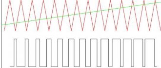
The shape of the magnetizing current of the transformer in saturation mode. Schedule.
Rice. 2.3. Construction of the magnetizing curve
transformer current
If the magnetic circuit of the transformer is not saturated, then the magnetizing current is sinusoidal; if the magnetic circuit is saturated, then the current is non-sinusoidal. But in any case, the magnetizing current is in phase with the magnetic flux. In a saturated transformer, the current is determined by the magnetization curve shown in Fig. 2.3 in the first quadrant.
What determines the active component of the no-load current?
The active component of the no-load current goes to cover power losses
(14.4)
Active component of no-load current I
0а =
I
0cosφ0 depends on no-load losses.
Almost I
0
I
c.
The active component Ica
, as indicated, is determined by losses.
Thus, the active component of the no-load current
,
where , and no-load current
.
How do constant losses in a transformer differ from variable losses?
A working transformer always has both magnetic and electrical losses. Magnetic losses in a transformer are composed of losses due to eddy currents and hysteresis:
The magnitude of these losses depends on the voltage U1 and magnetic induction B. We can assume that when U1 = const, ron = B2. They do not depend on the load, that is, they are constant.
Electrical losses in the windings , on the contrary, are variable , that is:
where pkn corresponds to losses during a short circuit of the transformer.
What can be done to reduce eddy current losses?
To reduce eddy current losses
- The magnetic cores of transformers and other electromagnetic devices are made not from solid masses, but from separate plates isolated from each other.
- The magnetic cores are made from sheets of high-alloy steel, the electrical resistivity of which is significantly greater than that of ordinary steel.
Thus, eddy current losses depend on the material of the magnetic circuit, the thickness of the steel plates and the insulation between them. In addition, eddy current losses are proportional to the squares of frequency and magnetic induction.
⇐ Previous3Next ⇒
What Causes Trends in Stock and Commodity Markets Freight Train Theory Explained My first 17 years of market research consisted of trying to figure out when...
Live by the rule: IS THERE NOT MUCH THING IN THE WORLD EXISTING? It is no coincidence that I emphasize that the space in your head is limited, but there is a lot of information around, and that your right...
What does the IS operation and maintenance department do? Responsible for the safety of data (copying schedules, copying, etc.)…
System of Protected Areas in the USA The study of specially protected natural areas (SPNA) in the USA is of particular interest for many reasons...
Didn't find what you were looking for? Use Google search on the site:
Why do we need a model of an ideal device?
The ideal transformer is often used in calculations of real structures. It is used as an equivalent of a real device in circuit diagrams and in problems of constructing electrical circuits. (For an example of constructing a circuit, see Fig. 4)
Rice. 4. Example of circuit synthesis
In practice, it is often necessary to make calculations for single-phase transformers and calculate the parameters of toroidal cores in order to provide the required power of toroidal devices. The size of the single-phase load determines what kind of electrical insulation needs to be used for power isolation models.
The choice of type of cooling of the windings of structures depends on the load mode in order to ensure the reliability of the transformer.
The fact is that it is very difficult to make an accurate calculation of a real device, since its parameters depend on variable magnetic components, including those that extend beyond the core. Foucault eddy currents create additional load resistance.
An isolation transformer is very difficult to calculate because its windings overlap each other, creating tangled eddy currents. It is almost impossible to monitor the phase shift occurring in these alternating currents.
The problem is simplified by the model of an ideal device. Using the equation for this imaginary device, it is easy to calculate all its parameters. They do not differ much from the parameters of the corresponding type of real device. The relative error does not exceed several percent, so it can be neglected.
By making calculations in various operating modes of a real device, it is possible to determine with high accuracy the values of rated loads using the equation for an imaginary transformer.
Instrument transformers.
At high voltages it is difficult to make measurements because high voltage instruments are expensive and usually bulky; their accuracy is susceptible to static electricity and they are not safe. When the current exceeds 60 A, it is not easy to ensure high accuracy of ammeters due to the large leads and significant errors caused by the parasitic field of the terminal leads. In addition, ammeters and current coils in high-voltage circuits are dangerous for the operator. Current and voltage instrument transformers use 100 V voltage coils and 5 A current coils. The secondary windings must be grounded. If instrument scales are not calibrated in transformation ratios, then the readings must be multiplied by the appropriate transformation ratio.
Voltage equations and MMF of a transformer
Based on the T-shaped equivalent circuit, the following voltage equilibrium equations (EMF) of the transformer can be written:
U1 = –E1+I1(R1+jX1)= –E1+I1Z1 , (1)
U2'= E2' – I2' (R2'+jX2' )= E2' – I2'Z2' . (2)
A feature of the operation of the transformer is that, due to the relative smallness of the resistances R1 and X1, the voltage drop I1Z1 in the range of normal loads is relatively small, as a result of which, according to equation (1),
E1~U1. In turn, the effective value of the emf E1 is proportional to the amplitude of the magnetic flux in the magnetic circuit Фm
U1 ~ E1 = 4.44f1W1Фm, (3) where W1 is the number of turns of the primary winding phase.
As follows from (3), the value of the magnetic flux is determined mainly by the primary voltage:
Фm ~ U1/4.44f1W1 (4) and for U1 = const also Фm ~ const.
When idling, the transformer consumes from the network the current Ix = I1 that is needed to create the required flux at a given voltage U1.
The value of the flux Фm is always such that the emf E1 induced by it, together with the voltage drop I1Z1 in accordance with equation (1), balances the applied voltage U1.
When connected to the secondary winding of the load, current I2 flows in it. Magnetomotive force of the secondary winding (its number of turns W2)
W2I2 = W1I2' (5).
strives to create its own flux in the magnetic circuit and thus change the flux that existed in the idle mode. However, as noted above, when U1=const this flow cannot change significantly (see formula 4). Therefore, the primary winding will consume from the network, in addition to the magnetizing current Ix, an additional current (–I2') of such a magnitude that the MMF created by it (–W1I2') will balance the MMF W1I2' of the secondary winding.
The current (–I2'), which magnetically balances the secondary current I2', is called the load component of the primary current.
The total primary current I1 consists of magnetizing Ix and load (–I2') components:
I1 = Ix+ (–I2'). (6)
Equality (6) is called the equilibrium equation of the MMF windings of the reduced transformer.
Transformer load mode.
If you turn on the secondary winding of the transformer to an external circuit by closing switch 4, the transformer goes from no-load mode to load mode.
It is obvious that from the moment the switch is turned on, a load current /2 appears in the secondary winding circuit. This current, like any changing current, creates its own alternating magnetic flux F2. Most of the F2 flux is closed along the transformer's magnetic conductor, and a smaller part of F2 is closed through the air around the turns of the secondary winding; it constitutes the magnetic leakage flux.
Being induced, the current of the secondary winding, according to Lenz’s rule, counteracts the cause that caused it, i.e., it has the direction opposite to the current /o, therefore its magnetic flux Ф2 is directed towards the flow Фo. In other words, the flume created by the secondary current would weaken the main magnetic flux Fo.
Kirchhoff equations for transformer circuits.
Reduction of numbers of turns of windings and vector diagram of the transformer.
When studying and analyzing the operating modes of a transformer, the task is complicated by the fact that the transformation coefficient k can have a relatively large value, and therefore difficulties arise in constructing a vector diagram of the transformer. The problem is solved by bringing the number of turns of the secondary winding to the number of the primary. Thus, the transformation ratio will become
For a transformer in which the parameters of the secondary winding are recalculated to the number of turns of the primary (reduced), the following equations are valid:
Let us determine the components of these equations, taking into account that the reduction should not change the operating mode of the primary circuit and the energy parameters of the secondary circuit should remain the same.
During reduction, the magnetizing force of the secondary winding should not change, therefore
Based on the fact that the electromagnetic power of the secondary winding should not change, we find the reduced EMF of the secondary winding E'2
Reduced voltage of the secondary winding
The reduced active resistance is found under the condition of equality of losses in the secondary winding
The reduced inductive reactance of the secondary winding is found similarly if the reactive powers are equal
Reduced impedance
Reduced load impedance
Current I0 is the no-load current, which is determined from the experience of no-load operation of the transformer.