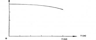
The most advanced method for diagnosing the ignition systems of modern cars is carried out using a motor tester . This device displays a high voltage waveform of the ignition system and also provides real-time information on ignition pulses, breakdown voltage, burn time and spark strength. The motor tester is based on a digital oscilloscope , and the results are displayed on the screen of a computer or tablet.
The diagnostic technique is based on the fact that any malfunction in both the primary and secondary circuits is always reflected in the form of an oscillogram. It is affected by the following parameters:
Checking the ignition with an oscilloscope
- ignition timing;
- crankshaft rotation speed;
- throttle opening angle;
- boost pressure value;
- composition of the working mixture;
- other factors.
Thus, using an oscillogram, you can diagnose faults not only in the car’s ignition system, but also in its other components and mechanisms. Ignition system failures are divided into permanent and sporadic (occurring only under certain operating conditions). In the first case, a stationary tester is used, in the second - a mobile one, used while the car is moving. Due to the fact that there are several ignition systems, the resulting waveforms will provide different information. Let's look at these situations in more detail.
Classic ignition
Let's look at specific examples of faults using oscillograms. In the figures, graphs of a faulty ignition system are indicated in red, respectively, in green - a working one.
Break after capacitive sensor
Break in the high-voltage wire between the capacitive sensor installation point and the spark plugs . In this case, the breakdown voltage increases due to the appearance of an additional spark gap connected in series, and the spark burning time decreases. In rare cases, the spark does not appear at all.
It is not recommended to allow prolonged operation with such a malfunction, since it can lead to breakdown of the high-voltage insulation of the ignition system elements and damage to the power transistor of the switch.
Broken wire in front of the capacitive sensor
Broken central high-voltage wire between the ignition coil and the installation point of the capacitive sensor . In this case, an additional spark gap also occurs. Because of this, the spark voltage increases and its lifetime decreases.
In this case, the reason for the distortion of the oscillogram is that when the spark discharge burns between the spark plug electrodes, it burns in parallel between the two ends of the broken high-voltage wire.
The resistance of the high-voltage wire between the installation point of the capacitive sensor and the spark plugs is significantly increased.
Increased resistance of the high-voltage wire between the installation point of the capacitive sensor and the spark plugs . The resistance of a wire can be increased due to oxidation of its contacts, aging of the conductor, or the use of too long a wire. Due to the increase in resistance at the ends of the wire, the voltage drops. Therefore, the shape of the oscillogram is distorted in such a way that the voltage at the beginning of the spark is significantly greater than the voltage at the end of the combustion. Because of this, the duration of the spark burning becomes shorter.
Faults in high-voltage insulation most often result in breakdowns. They can happen between:
- the high-voltage terminal of the coil and one of the terminals of the primary winding of the coil or “ground”;
- high-voltage wire and motor housing;
- ignition distributor cap and distributor housing;
- distributor runner and distributor shaft;
- “cap” of the high-voltage wire and the motor housing;
- the tip of the wire and the spark plug housing or engine housing;
- the central conductor of the spark plug and its body.
As a rule, in idling mode or at low engine loads, it is quite difficult to find insulation damage, including when diagnosing the engine using an oscilloscope or motor tester. Accordingly, the engine needs to create critical conditions for the breakdown to manifest itself clearly (engine starting, sharp opening of the throttle, operation at low speeds at maximum load).
After a discharge occurs at the site of insulation damage, current begins to flow in the secondary circuit. Therefore, the voltage on the coil decreases and does not reach the value required for a breakdown between the electrodes on the spark plug.
On the left in the figure you can see the formation of a spark discharge outside the combustion chamber due to damage to the high-voltage insulation of the ignition system. In this case, the engine operates under high load (over-throttle).
The surface of the spark plug insulator is heavily contaminated on the combustion chamber side.
Contamination of the spark plug insulator on the combustion chamber side . This can occur due to deposits of soot, oil, and residues from fuel and oil additives. In these cases, the color of the deposit on the insulator will change significantly. You can read information about engine diagnostics based on the color of carbon deposits on a spark plug separately.
Significant contamination of the insulator can cause surface spark discharges. Naturally, such a discharge does not ensure reliable ignition of the air-fuel mixture, which is why misfires occur. Sometimes, if the insulator is dirty, surface breakdowns may occur intermittently.
The shape of high voltage pulses generated by an ignition coil with interturn breakdown.
Breakdown of the interturn insulation of the ignition coil windings . In the event of such a malfunction, a spark discharge occurs not only on the spark plug, but also inside the ignition coil (between the turns of its windings). It naturally takes energy away from the main discharge. And the longer the coil is operated in this mode, the more energy is lost. At low engine loads, the described malfunction may not be felt. However, as the load increases, the engine may begin to “triple” and lose power.
Spark plug electrode gap and compression
The gap between the spark plug electrodes has been reduced. The engine is idling without load.
The mentioned gap is selected for each machine individually, and depends on the following parameters:
- maximum voltage developed by the coil;
- insulation strength of system elements;
- maximum pressure in the combustion chamber at the moment of spark formation;
- planned service life of the spark plugs.
The gap between the spark plug electrodes has been increased. The engine is idling without load.
By checking the ignition with an oscilloscope, you can find discrepancies in the distance between the spark plug electrodes. So, if the distance has decreased, then the likelihood of ignition of the fuel-air mixture decreases. In this case, a lower breakdown voltage is required for breakdown.
If the gap between the electrodes on the spark plug increases, the value of the breakdown voltage increases. Therefore, in order to ensure reliable ignition of the fuel mixture, it is necessary to operate the engine at low load.
Please note that long-term operation of the coil in a mode where it produces the maximum possible spark, firstly, leads to its excessive wear and early failure, and secondly, this is fraught with insulation breakdown in other elements of the ignition system, especially in high-voltage . There is still a high probability of breakdown of the switch elements, in particular, its power transistor servicing the problematic ignition coil.
Low compression . When checking the ignition system with an oscilloscope or motor tester, you can identify low compression in one or more cylinders. The fact is that with low compression at the moment of spark formation, the gas pressure is underestimated. Accordingly, the gas pressure between the electrodes of the spark plug at the moment of spark formation is also underestimated. Therefore, a breakdown requires less voltage. The shape of the pulse does not change, but only the amplitude changes.
In the figure on the right you see an oscillogram when the gas pressure in the combustion chamber at the moment of sparking is underestimated due to low compression or due to a large ignition timing. The engine in this case runs at idle speed without load.
Diagnostics by primary voltage
To diagnose an individual coil based on the primary voltage, you need to view the voltage oscillogram at the control terminal of the primary winding of the coil using an oscilloscope probe. Description of the picture:
Voltage oscillogram at the control terminal of the primary winding of a working individual ignition coil.
- The moment of opening of the power transistor of the switch (beginning of energy accumulation in the magnetic field of the ignition coil).
- The moment of closing the power transistor of the switch (the current in the primary circuit is abruptly interrupted and a breakdown of the spark gap occurs between the electrodes of the spark plug).
- The spark burning area between the spark plug electrodes.
- Damped oscillations that occur immediately after the end of the spark burning between the spark plug electrodes.
In the figure on the left you can see a voltage oscillogram at the control terminal of the primary winding of a faulty individual short circuit. A sign of a malfunction is the absence of damped oscillations after the end of the spark burning between the electrodes of the spark plug (section “4”).
DIS ignition system
High-voltage ignition pulses generated by healthy DIS ignition coils of two different engines (operating at idle speed without load).
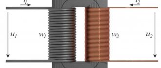
The DIS (Double Ignition System) ignition system has special ignition coils. They differ in that they are equipped with two high-voltage terminals. One of them is connected to the first end of the secondary winding, the second - to the second end of the secondary winding of the ignition coil. Each such coil serves two cylinders.
In connection with the described features, checking the ignition with an oscilloscope and taking an oscillogram of the voltage of high-voltage ignition pulses using capacitive DIS sensors occurs differentially. That is, the actual recording of an oscillogram of the output voltage of the coil is obtained. If the coils are working properly, then at the end of the combustion damped oscillations should be observed.
To diagnose the DIS ignition system based on the primary voltage, it is necessary to take voltage oscillograms on the primary windings of the coils one by one.
Description of the picture:
Voltage oscillogram on the secondary circuit of the DIS ignition system
- Reflection of the moment of the beginning of energy accumulation in the ignition coil. It coincides with the moment the power transistor opens.
- Reflection of the transition zone of the switch to the current limiting mode in the primary winding of the ignition coil at a level of 6...8 A. Modern DIS systems have switches without a current limiting mode, so there is no high-voltage pulse zone.
- Breakdown of the spark gap between the electrodes of the spark plugs served by the coil and the start of spark burning. Coincides in time with the moment the switch's power transistor closes.
- Spark burning area.
- The end of the spark burning and the beginning of damped oscillations.
Description of the picture:
Voltage oscillogram at the control terminal DIS of the ignition coil.
- The moment of opening of the power transistor of the switch (beginning of energy accumulation in the magnetic field of the ignition coil).
- The zone where the commutator switches to the current limiting mode in the primary circuit when the current in the primary winding of the ignition coil reaches 6...8 A. In modern DIS ignition systems, commutators do not have a current limiting mode, and, accordingly, there is no zone 2 on the primary voltage oscillogram absent.
- The moment of closing the power transistor of the switch (in the secondary circuit, a breakdown of the spark gaps between the electrodes of the spark plugs served by the coil occurs in the secondary circuit and the spark begins to burn).
- Reflection of a burning spark.
- Reflection of the cessation of spark burning and the beginning of damped oscillations.
Recommendations
Comments 11
The oscilloscope is not working correctly. The alternator and battery don't look right. The voltage is higher than normal, there is no synchronization with engine speed.
The voltage is intentionally high and has nothing to do with noise or needles.
The oscilloscope is not working correctly. The alternator and battery don't look right. The voltage is higher than normal, there is no synchronization with engine speed.
Show the right waveforms and oscilloscopes
This oscillogram is from what point?
The oscilloscope is not working correctly. The alternator and battery don't look right. The voltage is higher than normal, there is no synchronization with engine speed.
Why do I need synchronization with engine speed?
This is a generator test, B+. Synchronization is needed to understand what is going on and at what point in engine operation it occurs. The oscilloscope must work intermittently. On the battery it will be the same, only the amplitude is lower
Hello! What is scary is not the noise in the power supply from the generator, but the noise of ground interference... If you mean further noise in audio and video.
good afternoon! in other words, it's radio frequency interference right?
Well, judging by the oscillogram, the period is somewhere around 500 microseconds (
2 kHz), this is far from radio frequencies... But it lies in the audio frequency range.
period - yes, but the pulses are quite narrow, and on another generator (the pulses are larger) the oscilloscope showed 1 kHz.
when I had noise in the speakers, the input wires to the amplifier and the output wires to the speakers lay together and in parallel, it turned out that if they were separated by 10 cm and the transitions were placed perpendicular, the noise disappeared. Yes, I probably didn’t put it that way, not radio frequency, but magnetic fluxes.
you need to try turning off the generator and it may turn out that the interference is from the ignition coils...
Individual ignition
Individual ignition systems are installed on most modern gasoline engines. They differ from classic and DIS systems in that each spark plug is served by an individual ignition coil . As a rule, the coils are installed directly above the spark plugs. Occasionally, switching is done using high-voltage wires. There are two types of reels - compact and rod .
When diagnosing an individual ignition system, the following parameters are monitored:
- the presence of damped oscillations at the end of the spark burning section between the spark plug electrodes;
- the duration of time for energy accumulation in the magnetic field of the ignition coil (usually in the range of 1.5...5.0 ms depending on the coil model);
- duration of spark burning between the electrodes of the spark plug (usually 1.5...2.5 ms depending on the coil model).
Diagnostics by primary voltage
To diagnose an individual coil based on the primary voltage, you need to view the voltage oscillogram at the control terminal of the primary winding of the coil using an oscilloscope probe.
Description of the picture:
Voltage oscillogram at the control terminal of the primary winding of a working individual ignition coil.
- The moment of opening of the power transistor of the switch (beginning of energy accumulation in the magnetic field of the ignition coil).
- The moment of closing the power transistor of the switch (the current in the primary circuit is abruptly interrupted and a breakdown of the spark gap occurs between the electrodes of the spark plug).
- The spark burning area between the spark plug electrodes.
- Damped oscillations that occur immediately after the end of the spark burning between the spark plug electrodes.
In the figure on the left you can see a voltage oscillogram at the control terminal of the primary winding of a faulty individual short circuit. A sign of a malfunction is the absence of damped oscillations after the end of the spark burning between the electrodes of the spark plug (section “4”).
Secondary voltage diagnostics using capacitive sensor
Using a capacitive sensor to obtain an oscillogram of the voltage on the coil is more preferable, since the signal obtained with its help more accurately repeats the voltage oscillogram in the secondary circuit of the ignition system being diagnosed.
Oscillogram of a high voltage pulse of a serviceable compact individual fault, obtained using a capacitive sensor
Description of the picture:
- The beginning of energy accumulation in the magnetic field of the coil (coincides with the moment the power transistor of the switch opens).
- Breakdown of the spark gap between the electrodes of the spark plug and the start of spark burning (at the moment the switch's power transistor closes).
- The spark burning area between the electrodes of the spark plug.
- Damped oscillations that occur after the end of the spark burning between the electrodes of the spark plug.
Oscillogram of a high voltage pulse of a serviceable compact individual short circuit, obtained using a capacitive sensor. The presence of damped oscillations immediately after the breakdown of the spark gap between the spark plug electrodes (the area marked with the symbol “2”) is a consequence of the design features of the coil and is not a sign of a malfunction.
Oscillogram of a high voltage pulse of a faulty compact individual fault, obtained using a capacitive sensor. A sign of a malfunction is the absence of damped oscillations after the end of the spark burning between the electrodes of the spark plug (the area marked with the symbol “4”).
Secondary voltage diagnostics using an inductive sensor
When performing secondary voltage diagnostics, an inductive sensor is used in cases where signal acquisition using a capacitive sensor is impossible. Such ignition coils are mainly rod-based individual short circuits, compact individual short circuits with a built-in power cascade for controlling the primary winding, and individual short circuits combined into modules.
Oscillogram of a high voltage pulse of a serviceable individual short-circuit rod, obtained using an inductive sensor.
Description of the picture:
- The beginning of energy accumulation in the magnetic field of the ignition coil (coincides with the moment the power transistor of the switch opens).
- Breakdown of the spark gap between the electrodes of the spark plug and the start of spark burning (the moment the switch's power transistor closes).
- The spark burning area between the spark plug electrodes.
- Damped oscillations that occur immediately after the end of the spark burning between the spark plug electrodes.
Oscillogram of a high voltage pulse of a faulty individual short-circuit rod, obtained using an inductive sensor. A sign of a malfunction is the absence of damped oscillations at the end of the spark burning period between the spark plug electrodes (the area marked with the symbol “4”).
Oscillogram of a high voltage pulse of a faulty individual short-circuit rod, obtained using an inductive sensor. A sign of a malfunction is the absence of damped oscillations at the end of the spark burning between the spark plug electrodes and a very short spark burning time.
· Part 1 · Part 2 · Part 3 · Part 4 · Part 5 · Part 6 · Part 7 · Part 8 · Part 9 · Part 10 · Part 11 · Part 12 · Oscilloscope.
With and without it · Typical faults. Checks using an oscilloscope · Diagnostics and repair: Do-it-yourself oscilloscope Auto repair. Oscilloscope for troubleshooting, part 7 Continued.
The cause of this malfunction is creeping salts and electrified dust inside the unit. The reference voltage is 5.369V, which is above the permissible deviation.
Photo 10
This signal can be seen at the sensor output when the ignition is on and the engine is not running. The gain value is set by the panel. The signal is quite strong. But neither evil spirits nor other otherworldly forces have anything to do with it. Many, having seen something like this, are lost. A few more oscillograms, and then I will try to explain the essence of what is happening.
Photo 11
Photo 11 shows the sensor signal, which will also mislead the control system. I won’t say what will happen when the signal is digitized. And additional characteristics that give an understanding that the impulse is not ideal are difficult to apply here.
Photo 12.
Photo 12 is also far from bubblegum. The signal must be at a clear frequency. But she's not here. And where does all this come from?
Photo 13
I repeated photo 13 of the rectangular pulse. Now, if you examine it on an oscilloscope as if it were a dark green oscillogram, but at the same time remember that in reality it is like a light green one, then you can find an explanation. To this oscillogram we must also add that most sensors have their own amplifier inside. And the amplifier is not entirely simple. Although from an economic point of view it is cheap, and therefore it is installed in most modern sensors. It is assembled according to a circuit with a common emitter. The amplifier uses negative feedback. Since this is a pulse amplifier, there are some requirements for it. Input signals change quite quickly. And the main indicator for this type of amplifier is the impulse transfer characteristic. Transient processes for such an amplifier are decisive. And for accurate transmission of pulsed signals, phase and dynamic distortions must be kept to a minimum. This is solved by introducing feedback into the amplifier. Part of the signal from the output is fed to the input. The feedback depth is calculated, and any change in it will lead to distortion of the output signal. What can affect it? Yes, the sensor operates in conditions that are not entirely favorable from the point of view of exposure to external factors. One such factor is temperature. And its swings.
Photo14
Here is a sensor that has been in unfavorable conditions (external view)
Photo 15
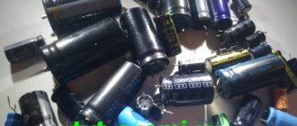
Photo 16.
Photos 15, 16 are what's inside. The soldering points made with refractory solder have acquired a “coarse” structure and we can talk about contact at the soldering points very conditionally. Even if it exists, the resistance at the solder points has clearly changed no less. This means that it is possible to change the value of the reference voltage inside the sensor itself, and the depth of feedback. That’s why we see “I don’t understand what” at the output. The speed of processes has changed. Phase distortions have emerged. In general, it is advisable to understand this... It seems to me that there is no particular point in analyzing the situation down to formulas for each case, modeling and determining what was the decisive factor: nutrition or changing the depth of feedback. It would be better to replace the sensor. But still, I’ll try to explain why the inversion occurs.
In photo 13, the oscillogram shows a short-term spike in amplitude when it reaches its maximum value. It is short-term and for rectangular pulses it must have a certain time and be a certain part of the maximum value. So, if “something” happens in the amplifier that will allow the process time to be delayed when the maximum surge occurs, and then the time for establishing the maximum amplitude follows (this is a section with damped amplitude oscillations at the maximum) and this time will be equal to the duration of the pulse itself - we will get at the output amplitude significantly exceeding the value of the reference voltage.
We look at the oscillograms, photo 1
And such a signal, with all its beauty and synchronicity, will not work. If this “something” occurs at the moment when the pulse amplitude is in the region of the minimum value emission and the time of establishment of the minimum amplitude, we get a “flip”, oscillogram 2:
That won't work either. It won’t work. If “something” that happened changed the depth of feedback in such a way that it turned the amplifier practically into a generator, leading to self-excitation, then you need to understand that the amplifier still did not lose its input. And since the system contains pulse signals even from the same clock generators, this means that their harmonics are also present. Which, yes, are weak, and even structurally weakened in order to exclude interference on other circuits, but they are there. And they also go to the amplifier input. And who said that they will not play the same role as the modulating signal in the modulator.
The carrier has already appeared, the amplifier is already excited. And then we get this, waveform 3:
For such an oscillogram there may be a question as an application: - “The sensor is in your hand, connected, the ignition is on... what is this?” You can consider more sensors... well, let's look again, but using not an oscilloscope, but a graphical display on a scanner, oscillogram 4:
After analyzing the graphs and data from the scanner and graphs, the decision was made to check the engine in more detail. Why? But because MAF readings directly depend on engine performance. It is not the sensor that “sucks” air, but the engine. And the sensor does not control anything, it simply records how much air has passed through it. And the system specifies - for a “certain period of time” (cycle). The sensor is working, there are no leaks. No, well, you can attack the corrections, the DC, the injectors, the ECU and try to hold them accountable ...
With signals to actuators it is much simpler. There are fewer white spots (which cannot be said about the errors that can be made), oscillogram 5:
There is a fault in the ignition coil.
You can, of course, give oscillograms of injectors, dampers and VVT valves, etc., but it seems to me that enough has already been said to determine the main thing when checking (diagnostics) a car when it does not work or does not work as it should.
What else plays a significant role? Of course, devices. Everyone's equipment is different. Therefore, without focusing on the oscilloscope, we have already given it its importance; we also talked about the scanner... A little can be said about ergonomics and capabilities.
Those who believe that a wide variety of devices allows for a better solution to the problem of troubleshooting... I don’t agree, or I agree, but with a reservation. Sometimes a specialist, using search techniques and completely unremarkable conventional devices, solves the problem no worse than someone who is equipped with dealer equipment. Of course, talking about the capabilities of the first and comparing them with the capabilities of the second is wrong. The capabilities of the devices are different and they not only expand the field of possibilities themselves, but also provide some advantages in the form of special functions. I would like to have a device with advanced capabilities. So that it allows you to reliably determine the malfunction, is easy to use and convenient to use. For example: oscillograms from the secondary ignition system are highly informative and reliable. But using an oscilloscope means... wires, a sensor, it’s a problem to get this sensor where it’s needed... In short, the device cannot be called ergonomic.
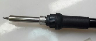
But such a device? –(photo by pribor)
It has a flexible probe, you can get it anywhere. Allows you to check any ignition system. Displays the number of revolutions, spark burning time, and breakdown voltage. I took it out, turned it on, brought the probe sensor to the desired point, received data (malfunction on the device screen). Agree, it’s both more convenient and faster than an oscilloscope (But such a device does not exclude an oscilloscope at all, rather it complements it). Various sensors are also not a hindrance, but help in certain moments (discharge, pressure, capacitive, inductive, etc. “stray” sensors... Even homemade ones. But if, using them, you find a malfunction, give up on critics who they puff out their cheeks because they use devices with branded stickers.The result is what is important.
By the way, about sensors, very good data are obtained from the use of an inductive sensor when checking injectors and other actuators. Still, a current oscillogram makes it possible to see a lot. What is not visible when connected directly to the circuit. The tactics for using sensors can be varied and are chosen based on need. A vacuum sensor, for example: it can be used as a probe, but with expanded capabilities, when you need to make sure that the mechanism is working correctly or that the timing belt is installed correctly. In this case, only the sensor signal is taken.
Graphic display of the signal allows you to quickly evaluate the operation of the mechanism.
Photo 18
The signals are simply compared. Visually, But this is already enough. If you need to look at something in more detail, you can do synchronization by injector or coil:
Photo 19.
Here, in photo 19. You can analyze it in more detail and with reference to a specific cylinder. Or, who can forbid you to use a pressure sensor to measure compression and compare it relative to cylinders (skeptics will ask: “why?”... but the compression meter is broken...). Moreover, I know how many Volts on the scale of my oscilloscope will correspond to 1KRA. In other words, no one limits your choice. But with opportunities the situation is somewhat different.
Photo 20
They used to do this too, especially when cars were being prepared for sale. We tightened the XX screw, the damper thrust screw, and turned the distributor body. In other words, “mechanical corrections” were performed, which made it possible to somewhat smooth out the manifestation of the malfunction, which manifested itself in unstable engine operation. Alas, now there is nothing to twist... or so little that the desired result cannot be achieved. The situation can be continued further: the client pays the money and leaves. Then, after some time, he realizes that the problem has not gone away... he goes to another specialist. And that one has more modest opportunities. He may not even be able to see with his instruments what the previous repairman did. And he will scrupulously check and, perhaps, eliminate the malfunction... but he will not get the desired result. And he will return the car, apologizing. Because he couldn’t... And he will be tormented by doubts. And the client will return to the one who had it, the one who made the corrections. And this same specialist, having forgotten what he did last time, simply sets “zeros”, and lo and behold! The machine is like a bird, and the specialist with puffed out cheeks and proudly raised head: “ We are here for you for a reason, we work at the program level
"It's a shame. Yes. But this option is quite possible.
But in this case, the client was lucky: they saw it, returned it to its place, and fixed the problem.
Photo 21
And two more points:
1 - the presence of various devices is not always beneficial. An example is when I was looking for a fault in a Qashqai. A cylinder-by-cylinder power balance test yielded results. But if you have an endoscope, you need to look inside. Visual perception is a convincing thing! ( and for the sake of a control check... and for the sake of curiosity... whatever, for self-affirmation “I’m right”
). Looked in... what did you get? And nothing but doubt. That’s why I didn’t see anything that would confirm the test result! All. And if doubt creeps in, then it’s time to roll “cotton balls”.
2 - I never give advice when asked what equipment is best to buy (options: this, or maybe this?)
Until he starts working, until he holds simple instruments in his hands, a person will not understand and will still have doubts. And when he starts working, the understanding of WHAT he needs will come to him on its own. And then he will be interested in the difference in characteristics and capabilities, based on working conditions.
That's all. It worked out a lot. Possibly stated “grumpily”. But he did not leave the intended line. And if anyone has found even a grain of useful information for themselves, then they wrote it for a reason.
· Part 1 · Part 2 · Part 3 · Part 4 · Part 5 · Part 6 · Part 7 · Part 8 · Part 9 · Part 10 · Part 11 · Part 12 · Oscilloscope. With and without it · Typical faults. Checks using an oscilloscope · Diagnostics and repair: Do-it-yourself oscilloscope
MARKIN Alexander Vasilievich
© Legion-Avtodata
Nickname on the Legion-Avtodata forum – A_V_M
Belgorod Tavrovo microdistrict 2, Parkovy lane 29B (4722)300-709
Design and principle of operation of the device
Let us explain the structure of an analog oscilloscope simply, “for dummies.” The device consists of the following elements:
- ray tube;
- power unit;
- vertical/horizontal deflection channel;
- beam modulation channel;
- synchronization and sweep trigger device.
There are controls to control the signal parameters and display it on the screen. Older models did not have a screen. The image was recorded on photographic tape.
Principle of operation
When the device starts, the signal is sent to the input of the vertical deflection channel. It has high input impedance. A voltmeter that measures voltage works on the same principle. However, the voltmeter does not show a time graph of voltage fluctuations.
The signal is amplified to the required level after being applied to the input. It is displayed on the screen along the vertical axis. Gain is required to operate the beam tube deflection system or the analog to digital signal converter. It allows you to change the scale of display of vibrations on the screen from large to small.
Device
The ray tube is sensitive to electrical impulses. The lower their frequency, the higher the sensitivity. In current tubes, the number of beams can range from one to 16. Their number corresponds to the number of signal inputs and graphs displayed simultaneously.
The peculiarity of a digital oscilloscope is that it has a screen and an analog signal converter. It has a memory to store data about the received oscillation graph. Some of the information is analyzed automatically and displayed in processed form. An analog oscilloscope does not store data, but only displays it in real time.
A sweep is the trajectory of a beam that picks up vibrations and displays an image on the screen. It comes in different shapes - elliptical, circular. The sweep value is adjusted depending on the signal being studied along the horizontal (time) axis.
The power supply supplies voltage from the 220 V network to the electronic circuits. There are also battery-powered models that can operate autonomously.
2Starting the DSO138 oscilloscope for the first time
Connect the power supply to the oscilloscope. The display should light up and the LED should blink twice. Then the manufacturer's logo and boot information will appear on the screen for a couple of seconds. After this, the oscilloscope will enter operating mode.
Let's connect the probe to the BNC connector of the oscilloscope and carry out the first test. Without connecting the black wire of the probe anywhere, touch the red wire with your hand. A pickup signal from your hand should appear on the oscillogram.
First test of the DSO138 digital oscilloscope - hand touch
What can you check with an oscilloscope?
This device can check all types of electrical signals from various parts of the car. Some of the most common uses of an oscilloscope are described below:
- Fuel supply system . Checking fuel injectors; checking the functionality of temperature sensors; as well as checking the mass air flow sensor, carburetor throttle position, oxygen sensor, and so on.
- Charging and power system . Checking the battery charging system, checking the operation of the generator.
- Ignition system. Determination of ignition timing, diagnostics of ignition system sensors, determination of faults in the ignition coil, determination of the condition of high-voltage spark plug wires and spark plugs.
- Gas distribution system. Checking the correct installation of the timing belt, assessing the relative compression of the cylinders when starting with the starter, assessing the compression in the engine operating mode and in the cranking mode, as well as checking the operation of the valves.