The most correct connection of several LEDs is in series. Now I will explain why.
The fact is that the determining parameter of any LED is its operating current. It is the current through the LED that determines what the power (and therefore the brightness) of the LED will be. It is the excess of the maximum current that leads to an excessive increase in the temperature of the crystal and failure of the LED - rapid burnout or gradual irreversible destruction (degradation).
Current is the main thing. It is indicated in the technical characteristics of the LED (datasheet). And depending on the current, the LED will have one voltage or another. Voltage can also be found in the reference data, but it is usually indicated in the form of a certain range, because it is secondary.
For example, let's look at the datasheet of LED 2835:
As you can see, the forward current is clearly and definitely indicated - 180 mA. But the supply voltage of the LEDs at this current has some variation - from 2.9 to 3.3 Volts.
It turns out that in order to set the required operating mode of the LED, it is necessary to ensure that a certain amount of current flows through it. Therefore, to power LEDs, you need to use a current source, not a voltage source.
A current source (or current generator) is a source of electrical energy that maintains a constant current through a load by varying the voltage at its output. If the load resistance, for example, increases, the current source automatically increases the voltage so that the current through the load remains unchanged and vice versa. The current sources that power LEDs are also called drivers.
Of course, you can connect a stabilized voltage source to the LED (for example, the output of a laboratory power supply), but then you need to know exactly what value the voltage should be to obtain a given current through the LED.
For example, in our example with the 2835 LED, we could apply about 2.5 V to it and gradually increase the voltage until the current becomes optimal (150-180 mA).
This can be done, but in this case you will have to adjust the output voltage of the power supply for each specific LED, because they all have technological variations in parameters. If, by connecting to one 3.1V LED, you received a maximum current of 180 mA, this does not mean that by replacing the LED with exactly the same one from the same batch, you will not burn it out (since the current through it at a voltage of 3.1V can easily exceed the maximum permissible value).
In addition, it is necessary to very accurately maintain the voltage at the output of the power supply, which imposes certain requirements on its circuitry. Exceeding the specified voltage by just 10% is almost guaranteed to lead to overheating and failure of the LED, since the current will exceed all imaginable values.
Here's a great illustration of the above:
Therefore, the most correct and simple solution would be to use a current driver (aka a current source) to connect the LEDs. And then it will be completely unimportant what kind of LED you take and what the forward voltage on it will be. You just need to find a driver for the required current and you're done.
Now, let's return to the main question of the article - why is there a serial connection and not a parallel one? Let's see what the difference is.
Parallel connection
When LEDs are connected in parallel, the voltage across them will be the same. And since there are no two diodes with absolutely identical characteristics, the following picture will be observed: through some LED a current will flow below the rated one (and the light will be so-so), but through the neighboring LED a current will flow twice as high as the maximum and It will burn out in half an hour (or maybe faster if you're lucky).
Obviously, such uneven distribution of power must be avoided.
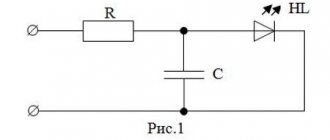
In order to significantly smooth out the spread in the performance characteristics of LEDs, it is better to connect them through limiting resistors. In this case, the power supply voltage can be significantly higher than the direct voltage on the LEDs. How to connect LEDs to a power source is shown in the diagram:
The problem with this LED connection circuit is that the greater the difference between the power supply voltage and the voltage on the diodes, the more useless power is dissipated in the limiting resistors and, accordingly, the lower the efficiency of the entire circuit.
Current limitation occurs according to a simple scheme: increasing the current through the LED leads to an increase in the current through the resistor too (since they are connected in series). The voltage drop across the resistor increases, and across the LED, accordingly, it decreases (since the total voltage is constant). Reducing the voltage on the LED automatically leads to a decrease in current. That's how it all works.
In general, the resistance of resistors is calculated using Ohm's law. Let's look at a specific example. Let's say we have an LED with a rated current of 70 mA, the operating voltage at this current is 3.6 V (we take all this from the datasheet for the LED). And we need to connect it to 12 volts. This means we need to calculate the resistance of the resistor:
It turns out that to power the LED from 12 volts you need to connect it through a 1-watt 120 ohm resistor.
In exactly the same way, you can calculate what the resistance of a resistor should be for any voltage. For example, to connect an LED to 5 volts, the resistor resistance must be reduced to 24 ohms.
The resistor values for other currents can be taken from the table (the calculation was made for LEDs with a direct voltage of 3.3 volts):
| 340 Ohm | 170 Ohm | 85 Ohm | 57 Ohm | 34 Ohm | 24 ohm | 17 ohm | 8.5 Ohm | 5.7 Ohm |
| 1.74 kOhm | 870 Ohm | 435 Ohm | 290 Ohm | 174 Ohm | 124 Ohm | 87 Ohm | 43 Ohm | 29 ohms |
| 4.14 kOhm | 2.07 kOhm | 1.06 kOhm | 690 Ohm | 414 Ohm | 296 Ohm | 207 Ohm | 103 Ohm | 69 ohms |
When connecting an LED to an alternating voltage (for example, to a 220 volt network), you can increase the efficiency of the device by using a non-polar capacitor (reactance) instead of a ballast resistor (active resistance). We discussed this point in detail and with specific examples in the article about connecting an LED to 220 V.
Series and parallel connections of diodes.
If for the rectifier circuit it is impossible to select the desired type of diode in accordance with the specified value of the reverse voltage or forward current, then two or more diodes of the same type with lower parameter values are used, including these diodes in series or in parallel.
Parallel connection of diodes
Parallel connection of diodes
When connecting diodes in parallel
due to possible scattering of parameters, their currents will be different. One of these currents may exceed the maximum permissible value, which will lead to failure of first one and then the other diode. A more uniform distribution of current between parallel-connected diodes is achieved by connecting resistors Rd of the same value in series with each of them. The resistance of the resistors Rd should be 5...10 times greater than the resistance of the diode in the forward direction. In powerful rectifier devices, inductive current equalizers are used for the same purpose.
Calculation of parallel connection of diodes
To start the calculation, you need to determine the required number of parallel-connected diodes
, based on the fact that the current passing through one diode should not exceed the maximum permissible current value for a given type of diode, then the number of parallel-connected diodes will be equal to
, Where
I
m
— maximum current value passing through the diodes,
k
T
– current load factor (can take values from 0.5 to 0.8),
I
n.p.
- average forward current for a given type of diode.
For fractional values of the estimated number of diodes, rounding is carried out upward.
value of additional resistors
determined by the formula
, Where
n is the number of rectifier diodes,
U
np.cp
— constant forward voltage for this type of diodes
The calculated resistance of additional resistors is rounded to the nearest standard resistance.
Example of calculation of parallel connection of diodes
Calculate a rectifier circuit that allows you to obtain a rectified current I rectified = 550 mA if D226B diodes are used.
Since the average forward current of the D226B diode Ipr. av = 300 mA, then it is necessary to use several parallel-connected diodes with additional resistors. Let's calculate the number of parallel-connected diodes, take kT = 0.8
Let's take n = 3.
Let's find the value of the resistance of additional resistors
Let's choose a resistor from the standard range of resistances E24 (± 5%) Rext = 6.2 Ohm
Series connection of diodes
Series connection of diodes
To ensure that the selected type of diode can operate in a rectifier circuit with a reverse voltage exceeding its maximum permissible value, diodes of the same type should be connected in series
. If the parameters do not match, then one of the diodes is under significantly higher voltage than the other. This can lead to breakdown of one and then another diode. Equalization of the reverse voltage on series-connected diodes is achieved by shunting each of the diodes with a resistor Rsh. The current flowing through these resistors should be 5...10 times greater than the maximum possible reverse current of the diodes. In powerful high-voltage rectifier devices, for the same purpose, diodes are shunted with capacitors Сш or an RC circuit.
Calculation of series connection of diodes
To start the calculation, you need to determine the number of diodes connected in series
, based on the fact that the voltage drop on each individual diode should not exceed the amplitude voltage value, then the number of diodes connected in series will be equal to
, Where
Um is the amplitude value of the voltage passing through the diode, kH is the voltage load factor (can take values from 0.5 to 0.8), Uobp max is the maximum permissible reverse voltage of the diode.
For fractional values of the estimated number of diodes, rounding is carried out upward.
Shunt resistor resistance values
determined by the formula
, Where
Iobp max - maximum permissible reverse current of the diode at maximum temperature.
An example of calculating a series connection of diodes
Calculate the rectifier circuit for a voltage with an amplitude value of 700V using D226B diodes.
Since the maximum permissible reverse voltage of the diode is Urev.max = 300V, for rectification it is necessary to use a chain of series-connected diodes with shunt resistors. Let's calculate the number of series diodes, take kH = 0.7
Let's take n = 4
Let's find the value of the resistance of the shunt resistors
Let's choose a resistor from the standard range of resistances E24 (± 5%) Rsh = 1 MOhm
The inclusion of additional and shunt resistors is inevitably associated with an increase in power losses and a decrease in the efficiency of the rectifier circuit.
Serial connection
When LEDs are connected in series, the same current flows through them. The number of LEDs does not matter, it could be just one LED, or it could be 20 or even 100 pieces.
For example, we can take one 2835 LED and connect it to a 180mA driver and the LED will operate normally, delivering its maximum power. Or we can take a garland of 10 of the same LEDs and then each LED will also work in normal passport mode (but the total power of the lamp, of course, will be 10 times greater).
Below are two LED switching circuits, pay attention to the difference in voltage at the driver output:
So to the question of how the LEDs should be connected, serial or parallel, there can only be one correct answer - of course, serial!
The number of LEDs connected in series is limited only by the capabilities of the driver itself.
An ideal driver can infinitely increase the voltage at its output to provide the required current through the load, so an infinite number of LEDs can be connected to it. Well, real devices, unfortunately, have a voltage limit not only from above, but also from below.
Here is an example of a finished device:
We see that the driver is able to regulate the output voltage only within the range of 64...106 volts. If to maintain a given current (350 mA) you need to raise the voltage above 106 volts, then it’s a bummer. The driver will output its maximum (106V), and what the current will be is no longer dependent on it.
The presence of a minimum voltage is explained (depending on the circuit design) by limitations on the power of the output control element or by exceeding the limiting generation modes of the pulse converter.
Of course, drivers can be for any input voltage, not necessarily 220 volts. Here, for example, is a driver that converts any constant voltage source (power supply) from 6 to 20 volts into a 3 A current source:
That's all. Now you know how to turn on an LED (one or more) - either through a current-limiting resistor or through a current-setting driver.
How to choose the right driver?
Everything is very simple here. You only need to choose according to three parameters:
- output current;
- maximum output voltage;
- minimum output voltage.
The output (operating) current of the LED driver is the most important characteristic. The current should be equal to the optimal current for LEDs.
For example, we had at our disposal 10 pieces of full-spectrum LEDs for a phytolamp:
The rated current of these diodes is 700 mA (taken from the reference book). Therefore, we need a 700 mA current driver. Well, or a little less to extend the life of the LEDs.
The maximum output voltage of the driver must be greater than the total forward voltage of all LEDs. For our phytoLEDs, the forward voltage is in the range of 3...4 volts. We take it to the maximum: 4V x 10 = 40V. Our driver must be able to output at least 40 volts.
The minimum voltage , accordingly, is calculated based on the minimum value of the forward voltage on the LEDs. That is, it should be no more than 3V x 10 = 30 Volts. In other words, our driver must be able to reduce the output voltage to 30 volts (or lower).
Thus, we need to select a driver circuit designed for a current of 650 mA (let it be slightly less than the nominal one) and capable of outputting a voltage in the range from 30 to 40 volts as needed.
Therefore, for our purposes something like this will do:
Of course, when choosing a driver, the voltage range can always be expanded in any direction. For example, instead of a driver with a 30-40 V output, one that produces from 20 to 70 Volts is perfect.
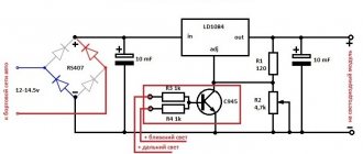
By the way, to connect the LEDs correctly, it is not at all necessary to buy a ready-made driver; you can simply take some suitable power supply (for example, a phone charger) and screw a simple current stabilizer to it on one transistor or on LM317.
Ready-made current stabilizer circuits for LEDs can be taken from this article.
In lamps and flashlights, two circuits are used - serial and parallel connection of LEDs. These schemes have a lot of variations and combined options, each of them has its own advantages and disadvantages.
To understand which connection diagram is better, you need to find out what the current-voltage characteristic is and what it is like for an LED.
The photo shows an LED matrix for connecting to a 220V network
Basic theoretical issues
Current-voltage characteristic (abbr. VAC) is a graph displaying the dependence of the amount of current flowing through any device on the voltage applied to it. A simple and very capacious characteristic for the analysis of nonlinear components. With its help, you can select operating modes and determine the characteristics of the power source for the device.
Take a look at an example of linear and nonlinear I-V curves.
Graph number 1 in the figure displays the linear dependence of current on voltage, which is what all resistive devices have, for example:
- Incandescent lamp;
- heater;
- resistor (resistance);
Graph number 2 is the current-voltage characteristic characteristic of pn junctions of diodes, transistors and diodes.
Common mistakes when creating a parallel connection
No one is immune from this, but we should try to prevent this from happening. The main mistakes that not only beginners, but sometimes even professionals make are:
- Ignoring the need to connect an LED with a limiting resistor.
- Switching several LED components through one resistor. In such a case, if one of the elements is broken, the current on the others will increase significantly. What this entails is not worth talking about.
- Series connection of LEDs with different characteristics.
- Insufficient resistance. The current passing through the emitter will be too large, which will lead to an increase in temperature and failure of the element.
- Connecting LEDs to a household network without a reverse voltage limiting device. The network current is 220 V AC, which means that the moment the sinusoid crosses the axis, a breakdown of the pn junction of the element will occur, which will lead to its failure.
- Low resistance power. Even with the correct parallel connection of the LEDs, such an error will lead to strong heating of the resistor, melting of the insulation and a short circuit.
It remains to advise home craftsmen to be more attentive to such work and avoid making the listed mistakes.
Learn more about how diodes work
Which LED connection should I choose: series or parallel? This greatly depends on the operating conditions and the power source, as well as the voltage and current stabilization system. To make the right choice, you need to consider both options.
Initially, we were talking about the current-voltage characteristic for a reason; let’s consider in detail its form for LED devices.
Please note that in the voltage range lower than 2.5V, very little or no current flows through the LED. Having overcome the level of 2.5 volts, current begins to flow through the diode and it lights up in the area from 2.5 to 3 volts. After this level, the current begins to increase rapidly.
For 5 mm white light diodes, the operating current is 20 mA at 3V, and at 3.5 volts the current will be 80 mA, which is four times higher than the nominal value.
Although the brightness of the diode depends on the current flowing through it, at excessively high values the LED does not glow much brighter than at nominal value. Therefore, you should not experiment with high indicators - your diodes will simply burn out.
Voltage values may vary depending on the types and design of LEDs, this is influenced by their number in one package, color, and even the material that was chosen as the basis of the chip.
How to connect correctly?
When connecting LEDs in parallel, you need to use a limiting resistor for each diode, as shown in the figure below. This makes it possible to set the current for each of the elements of the electrical circuit.
LED Parallel Connection Diagram
Below is a diagram of NOT correctly connecting a resistor to a circuit.
This is not the right way to connect
When connecting LEDs and any other consumers in parallel, the voltage at their terminals will be equal. On the one hand, this is good, but not for diodes. Each LED, even a set taken from the same batch, has a small technological variation in parameters. The voltage required to achieve the rated current may vary slightly within tenths of a volt.
Above you saw the current-voltage characteristic of the device and you can easily conclude that a slight excess of the rated voltage leads to an avalanche-like increase in current and overheating. Some suggest excluding the resistor from this circuit; this connection of LEDs is the worst!
The total current in the circuit is equal to the sum of the currents in each of the branches of the parallel circuit. If you choose how to connect LEDs to operate in a circuit with high voltage (6 volts or more), it is better to use a series connection.
Why are diodes connected in parallel?
The main purpose of paralleling a diode is to increase their forward current. This is the main parameter of each diode. However, there are a large number of diodes designed for different current values over a wide range. Therefore, a conventional parallel connection does not completely solve the issue of increasing the total forward current.
If each of the diodes connected in parallel has a forward current of 1 ampere and a maximum reverse voltage of 100 volts, then the entire chain will have parameters of 3 amperes and 100 volts. That is, parallel connection implies an increase in forward current, proportional to the number of connected diodes. At the same time, the maximum value of the reverse voltage remains unchanged.
When diodes with different characteristics are connected in parallel, the distribution of forward current will be uneven. The diode with the least resistance will carry more current in the forward direction. Under certain circumstances, such an excess can become critical and lead to diode breakdown. In order to avoid this situation, a resistor is connected in series with each LED. Their resistance is selected on the basis that the voltage will drop by no more than 1 volt.
Online calculator for calculating a resistor
| Connection type: | One LED Serial connection Parallel connection |
| Supply voltage: | Volt |
| LED forward voltage: | Volt |
| Current through LED: | Milliamp |
| Number of LEDs: | PC. |
| Results: | |
| Exact resistor value: | Ohm |
| Standard resistor value: | Ohm |
| Minimum resistor power: | Watt |
| Total power consumption: | Watt |
Serial connection
In electrical engineering, not only parallel connection of diodes is used. For high-voltage circuits, their series connection is often used. With this connection option, the voltage is distributed evenly between all connected diodes.
However, different values of return currents must also be taken into account here. Thus, in the case of a series connection, most of the applied voltage will drop across the diode having minimal reverse current. If the permissible reverse voltage value is exceeded, diode breakdown may occur. Therefore, here the voltage drop is also artificially equalized, for which special shunt resistors are used.
Connection options
To make a serial connection of 220V LEDs, use the diagram below.
In this case, capacitor C1 limits the current to a greater extent; it plays the role of reactance. We wrote more about calculating a capacitor in the article . To obtain the required capacitance value of the capacitor, use the online calculator:
This way you can connect even one LED.
If you want to build a 100 volt DC LED series circuit, you need to include about 30 LEDs in the circuit. Then the required voltage will be about 90 volts. Calculate the resistor using the formula in the previous sections of the article.
A capacitor is needed to smooth out current ripples, a resistor in parallel is needed to discharge the capacitor after turning off the device, for safety reasons. If the power source is sufficiently stabilized, they can be excluded.
Alternative connection type
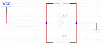
Series-parallel connection of LEDs - found in floodlights and other powerful lamps operating on both direct and alternating voltage.
As you can see, the matrix is divided into branches, each of which has a current-limiting resistor. A specific copy is intended to replace the standard courtesy lamp in the car interior. If one diode fails, one circuit will stop lighting, and the remaining circuits will continue to glow.
If you can't decide whether to connect LEDs in series or parallel, there is an alternative option - a hybrid connection. At first glance, it is not clear what the point is.
The hybrid version takes advantage of the serial and parallel connection of LEDs. The circuit will work fully even if one of the elements in the circuit burns out, while at the same time the remaining elements will not experience overload. The voltage on each segment will be limited to the LED with the lowest drop.
To assemble the lamp correctly, and to ensure that the LEDs work for a long time and do not overheat, you need to decide how to connect the LEDs - in series or in parallel. You have become familiar with the strengths and weaknesses of each option. Thanks to the knowledge gained, you can repair an LED lamp or spotlight.
Please rate the article. We tried our best:)
(ratings, average: out of 5)
Did you like the article? Tell us about her! You will help us a lot :)
Connecting one LED will never create big problems. What to do if you need to power two, three, four or more LEDs? Right. You need to collect LEDs into a string (chain). Connections can be of several types: parallel connection of LEDs, serial and parallel-series. I will write a few words about these connections. Perhaps it will be useful to someone.
For those who don’t know yet, the most optimal is a series connection of LEDs. In this case, the current on each LED connected in series will be the same. This connection allows us to easily control the currents.
However, despite this, there are power supplies whose power will not allow powering serial LEDs. In this case, parallel connection of LED sources will help us.
The nuances of connecting LEDs
As you know, there is a serial and parallel connection of LEDs. In this case, the question arises, why is one chosen for garlands with incandescent lamps and neon, and another for LED elements? Here it comes down to the characteristics of the emitters. Each LED has its own voltage drop indicator. Provided that the stabilizing power supply is not too powerful, a large number of LED elements cannot be connected in series to it. It is for this reason that parallel switching is used in garlands.
Someone may say that it is enough to take a more powerful power supply, because in this case it will be easier to control the voltage on the LEDs (it will be equal on each of them). But this is where the problem arises. Even if you take a regular garland of LEDs with 50 LED elements, the adapter will be of such a size that it will not be possible to hide it under a small Christmas tree.
Helpful information! If the voltage drop across the chips is higher than the power supply rating, such an adapter may not withstand long-term operation.
Parallel connection of LEDs is not correct
I repeat once again - parallel connection of LEDs is used only when the power source is low voltage.
Despite the fact that this type of connection is not very welcome, it is often used. There is one rule in these types of connections - parallel connection of LEDs is never done using ONLY ONE resistor!!!
Well, or for those who only understand visual pictures, an incorrect parallel connection will look like this:
Naturally, the question arises - WHY can’t it be connected like this? And the point here is simple...
Correct parallel connection of LEDs
The picture shows the correct parallel connection of LEDs. This method differs from the version with one resistor in that each diode is connected in parallel through its own resistor. Such a connection will not allow distortion to occur. Even if for some reason the LED burns out, the second one will not receive increased voltage.
Calculation of resistance when connecting LEDs in parallel
Let's consider parallel connection of LEDs using the example of two power supplies. The data will be obtained based on twice the current consumption. Those. the limiting resistor has half the resistance than. if we powered one LED. In any case, it is worth remembering that no two LEDs are identical, even if they were produced by the same factory and from the same batch. All diodes have a variation in current consumption and internal resistance. A crystal with less resistance will draw more current. Thus, some distortion will arise. This can be determined visually. With higher consumption, the diode will glow stronger, with lower consumption, weaker. If the diodes are from the same batch, then the distortion will not be very noticeable, but if the LEDs are also from different manufacturers, then it is quite possible that the diode will burn out.
Let's go back to our sheep... The resistor is designed for double current consumption, and therefore if one burns out, the second one receives double the voltage and double the current. This is also critical. This rule is true not only for connecting two LEDs in parallel, but also for larger numbers with one resistor. If one burns out, the rest will fail in the shortest possible time, due to proportionally increasing voltage and current.
Parallel connection
The need for parallel connection arises when the power source voltage is not enough to power several series-connected LEDs. Theoretically, in the simplest version, it would be possible to separately combine all the anodes and all the cathodes of the emitting diodes. Then connect them to the voltage source, observing the polarity. But such a circuit is not operational , since the differential resistance of an open LED is too small, which provokes a short circuit. As a result, all LEDs in the circuit will flash once and go out forever.
But as they say: “There are no rules without exceptions.” In Chinese illuminated toys and lighters, you can see that the LEDs are powered directly from batteries without any intermediate elements. Why don't they burn out? The fact is that the current in the circuit is limited by the internal resistance of round AG1 batteries. Their power is not enough to harm the LED.
You can limit a sharp increase in current in the load using a resistor. How to do this correctly with one LED is described in detail in this article. For a chain of several LEDs connected in parallel with one resistor, the circuit will take the following form. But this option is not suitable for designing lighting devices with high reliability. Why? The answer to this question lies in the structural features of semiconductors. During the production of semiconductor elements, it is impossible to obtain two absolutely identical devices. Even LEDs from the same batch will have different differential (internal) resistance, on which the forward voltage depends. This applies not only to LEDs, but also to other semiconductors. Among diodes, transistors and thyristors, you also cannot find two devices with equal electrical parameters.
From the second diagram it can be seen that resistor R1 limits only the total current of the circuit, which is then distributed among the branches with LEDs depending on their resistance. According to Ohm's law, the LED with the lowest pn junction resistance will receive the largest portion of current. And most likely it will be greater than the nominal value, which will accelerate the degradation of the crystal. Operating an LED in overcurrent mode will sooner or later lead to failure due to an open circuit. The remaining LEDs will distribute the current of the burnt element among themselves, which will also lead to a sharp loss of brightness.
As in the first option, the Chinese do not hesitate to design lamps based on “semi-working” circuits. A circuit with one resistor can often be found in cheap flashlights and low-power lamps using AA batteries. And in order for the LEDs to work for at least a year, the resistance of the resistor is deliberately increased, as if to exclude possible overloads.
Below is the only correct option for parallel connection of LEDs. Here a limiting resistor is connected in series with each LED. This circuit solution makes it possible to equalize the currents in each individual branch, not allowing them to exceed the operating value.
It is recommended to connect LEDs through a resistor only from a stabilized DC voltage source.
Calculation example
To consolidate theoretical knowledge, we will consider parallel connection of LEDs using a specific example. The circuit includes two LEDs: low-current red and powerful one-watt white, which for convenience can be powered from different switches.
Given:
- voltage source U = +5 V;
- LED1 – red light with ULED1 = 1.8 V and ILED1 = 0.02 A;
- LED2 – white light with ULED2 = 3.2 V and ILED2 = 0.35 A.
It is necessary to calculate the parameters and select resistors R1 and R2.
When connected in parallel, the same voltage of 5 V is applied to both branches (R1-LED1 and R2-LED2). The resistance of each resistor is determined by the formula: We round the resulting value of R2 to the nearest larger value from the standard E24 series - 5.1 Ohms. Substituting it back into the formula, we find the real current in the second branch: Taking into account the possible deviation of the resistance of the selected resistor, which for the E24 series can reach 5%, a current of 0.33 A is optimal. Reducing the operating current by about 4% will not greatly affect the brightness, but will allow the LED to operate without overload.
The power that the resistors must dissipate will be determined taking into account the recalculation of the LED2 current using the formula: Resistor R1 is suitable for any type, either planar or with leads with a resistance of 160 Ohms and a power of 0.125 W. The housing of resistor R2 must effectively remove heat during long-term operation of the lamp. Therefore, we choose it with a double power reserve, namely: 5.1 Ohm - 1 W.
Pros and cons of parallel LED connection
A big advantage of a parallel connection is that if the LEDs are connected correctly, if one of them burns out, the rest will work. When LEDs are connected in series, failure of one of them will cause the row of series-connected chips to stop lighting.
The disadvantage of parallel connection of LEDs is that the design becomes more expensive due to the fact that new elements appear in the circuit. As a result, the final product can be quite bulky.
It’s worth imagining a Christmas tree garland with such a connection of diodes... For it to work, you will have to connect another conductor to the LED-resistor pair. Therefore, 99.9% of all garlands are assembled from series-connected LEDs.
Parallel connection
Light-emitting diode (LED) is a microelement whose operation depends on many parameters. Errors in microtechnology lead to the fact that the current-voltage characteristic of each individual LED is different. Therefore, the response threshold (“turning on”) of all diodes is different at the same time. This is allowed by quality standards and must be taken into account when constructing electrical circuits. Parallel connection of LEDs requires exactly this setting for them to fire simultaneously.
Parallel connection diagram
The electrical diagram shows that each LED has its own resistor. When configured, resistors R1-R6 regulate the operation of the entire system. The response threshold of each diode is in the range of 2.5-3.0 Volts, so resistors must be selected for each diode.
A positive indicator is the low-voltage characteristic. The response level of one LED is up to 3.0 V, so the entire light assembly can be designed for low voltage.
A significant advantage of parallel connection is the “survivability” of this option. If one LED element fails, the system continues to operate and provide lighting.
This quality is used in mini-devices, when miniaturization is important and they are assembled on rechargeable “tablets”. Such crafts are widely produced by industry and are intended for small tasks - local illumination, advertising purposes, etc.