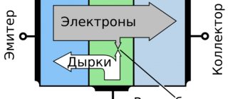
The standard design of a semiconductor diode is made in the form of a semiconductor device. It has two terminals and one rectifying electrical junction. The entire system is connected in a single housing made of plastic, glass, metal or ceramic. The part of the crystal with a higher concentration of impurities is called the emitter, and the area with a lower concentration is called the base. Diode markings and designation schemes are used in accordance with their individual properties, design features and technical characteristics.
Characteristics and parameters of diodes
Depending on the material used, diodes can be made of silicon or germanium. In addition, indium phosphide and gallium arsenide are used for their production. Germanium diodes have a higher transmission coefficient compared to silicon products. They have high conductivity at relatively low voltage. Therefore, they are widely used in the production of transistor receivers.
In accordance with technological characteristics and designs, diodes are distinguished as planar or point, pulse, universal or rectifier. Among them, a separate group should be noted, which includes LEDs, photodiodes and thyristors. All of the above signs make it possible to identify a diode by appearance.
The characteristics of diodes are determined by such parameters as forward and reverse currents and voltages, temperature ranges, maximum reverse voltage and other values. Depending on this, appropriate markings are applied.
Color coding
Many radio amateurs know that most diodes, unfortunately, are alike. However, it should be noted that some devices are still marked with special color markings, which make it possible to immediately identify such devices. If you look at the diode marking table, you can say that they are divided into 2 main types. We are talking about the designation of the anode and cathode, and manufacturers often replace the body color with a regular colored dot.
At first glance, you can distinguish any colored diodes, which will be discussed below.
For example, diodes of the KD410 family are distinguished by the fact that they have a point in the area of the anode. The case is transparent for KD102 diodes. The KD274 device has two colored rings near the cathode. It should be noted that there are also other distinguishable marks that will make it easy to distinguish devices from each other.
Many beginners, when considering the types of diodes, unfortunately, cannot determine where the anode is and where the cathode is. It should be noted that new devices that are being created in modern times operate in such a way that the anode has a tendril slightly longer than the cathode. Also, if a person knows how to use a multimeter, he can easily distinguish the anode from the cathode. The cathode can also be found by a dark stripe when looking at the side of the cylinder. This is also color coded.
Foreign manufacturers have their own designation system. If you need to select an analogue, you should use correspondence tables. Otherwise, the characteristics of the devices do not differ from domestic ones. Color marking, as well as many other designations of diode parameters, as a rule, corresponds to either US standards or the European system.
Marking of imported diodes
Currently, foreign-made SMD diodes are widely used. The design of the elements is made in the form of a board, on the surface of which a chip is fixed. The dimensions of the product are too small to allow marking to be applied to it. On larger elements, designations are present in full or abbreviated versions.
In electronics, SMD diodes make up about 80% of all products of this type used. Such a variety of details makes you pay more attention to the designations. Sometimes they may not coincide with the declared technical characteristics, so it is advisable to carry out additional checks of questionable elements if they are planned for use in complex and precise circuits. It should be borne in mind that the markings of diodes of this type may be different on completely identical cases. Sometimes there are only alphabetic symbols, without any numbers. In this regard, it is recommended to use tables with diode sizes from different manufacturers.
For SMD diodes, the SOD123 package type is most often used. A colored stripe or embossing may be applied to one of the ends, which indicates a cathode with negative polarity to open the pn junction. The only inscription corresponds to the designation of the case.
The type of housing does not play a decisive role when using a diode. One of the main characteristics is the dissipation of some amount of heat from the surface of the element. In addition, the values of the operating and reverse voltages, the maximum permissible current through the pn junction, power dissipation and other parameters are taken into account. All this data is indicated in reference books, and marking only speeds up the search for the desired element.
Marking
If we talk about the designation of diodes, then it should be said that in the first place there will be a letter or number that characterizes the material. These can be gallium, silicon, germanium and indium. Accordingly, the following letters (numbers) will be printed on the body: A (3), K (2), G (1), I (4). In second place will be the diode characteristic. It must be said that, as a rule, its decoding should be found in the instructions. The most popular designation is D. This means that the device is rectifier or impulsive type. In third place there will be a number that characterizes the scope of application of the diode. Numbers from 1 to 9 are used here. The minimum characteristic is 1 - low-frequency, which have a current below 0.3. Nine means impulsiveness, in which the carrier lifetime will be much lower than 1 ns. The development number may or may not be specified.
It should be noted that a denomination that has a single-digit number is always preceded by a zero. For example, batch 7 will be written as 07. The group number of manufacturers is usually indicated by a letter. Thanks to it, you can find out various properties and parameters of the device. It also indicates the voltage, current supplied, and so on.
Introduction
Light Emitting Diode (LED) is a semiconductor diode capable of emitting light when voltage is applied to it in the forward direction. Essentially, it is a diode that converts electrical energy into light. Depending on the material from which the LED is made, it can emit light of different wavelengths (different colors) and have different electrical characteristics. LEDs are used in many areas of our lives as means of displaying visual information. For example, in the form of single emitters or in the form of structures from several LEDs - seven-segment indicators, LED matrices, clusters, and so on. Also, in recent years, LEDs have actively occupied the lighting segment. They are used in car headlights, lanterns, lamps and chandeliers.
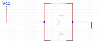
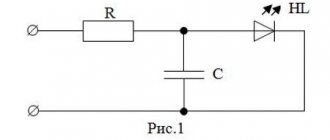
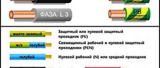
On electrical diagrams, an LED is indicated by a diode symbol with two arrows. The arrows are directed away from the diode, symbolizing light radiation. Do not confuse it with a photodiode, which has arrows pointing towards it. On domestic diagrams, the letter designation of a single LED is HL.
A standard single-color LED has two terminals - the anode and the cathode. You can determine which terminal is the anode visually. For lead wire LEDs, the anode is usually longer than the cathode.
SMD LEDs have the same leads, but on the back side there is usually a marking in the form of a triangle or something like the letter T. The anode is the lead to which one side of the triangle or the top of the letter T faces.
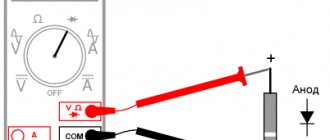
If you can’t visually determine which pins are which, you can ring the LED. To do this, you will need a power source or adapter capable of delivering a voltage of about 5 Volts. We connect any LED terminal to the negative terminal of the source, and connect the second to the positive terminal of the source through a resistance of 200 - 300 Ohms. If the LED is connected correctly, it will light up. Otherwise, we swap the pins and repeat the procedure. You can do without a resistor if you do not connect the positive terminal of the power source, but quickly “strike” it across the LED output. But in general, it is impossible to apply high voltage to the LED without limiting the current - it may fail!
An LED emits light if voltage is applied to it in the forward direction: positive to the anode and negative to the cathode.
The minimum voltage at which an LED starts to glow depends on its material. The table below shows the LED voltages at a test current of 20 mA and the colors they emit. I took this data from the Vishay LED catalog, various datasheets and Wikipedia.
The highest voltage is required for blue and white LEDs, and the smallest for infrared and red. The radiation of an infrared LED is not visible to the human eye, so such LEDs are not used as indicators. They are used in various sensors and video camera lights. By the way, if you power an infrared LED and look at it through a mobile phone camera, its glow will be clearly visible.
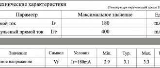
The table shown gives approximate LED voltage values. Usually this is enough to turn it on. The exact forward voltage of a particular LED can be found in its datasheet in the Electrical Characteristics section. It indicates the nominal value of the forward voltage at a given LED current. For example, let's look at the datasheet for a red SMD LED from Kingbright.
The current-voltage characteristic of an LED shows the relationship between the applied voltage and the current of the LED. The figure below shows a direct branch of the characteristic from the same datasheet.
If the LED is connected to a power source (to the anode +, to the cathode -) and gradually increases the voltage on it from zero, then the LED current will change according to this graph. It shows that after passing the “bending” point, the current through the LED will increase sharply with small changes in voltage. This is precisely the reason why an LED cannot be connected to any power source without a resistor, unlike an incandescent light bulb. The higher the current, the brighter the LED glows. However, it is naturally impossible to increase the LED current to infinity. If the current is high, the LED will overheat and burn out. By the way, if you immediately apply high voltage to the LED, it can even flop like a weak firecracker!
What other LED characteristics are of interest from the point of view of practical use? Maximum power dissipation, maximum values of direct and pulsed forward currents and maximum reverse voltage. These characteristics show the limit values of voltages and currents that should not be exceeded. They are described in the datasheet in the Absolute Maximum Ratings section.
If you apply voltage to the LED in the opposite direction, the LED will not light up, and may even fail. The fact is that with reverse voltage a breakdown may occur, as a result of which the reverse current of the LED will increase sharply. And if the power released by the LED (reverse current * reverse voltage) exceeds the permissible limit, it will burn out. Some datasheets also provide the reverse branch of the current-voltage characteristic, from which it is clear at what voltage a breakdown occurs. Radiation intensity (luminous intensity) Roughly speaking, this is a characteristic that determines the brightness of the LED at a given test current (usually 20 mA). It is designated Iv and is measured in microcandelas (mcd). The brighter the LED, the higher the Iv value. The scientific definition of luminous intensity is on Wikipedia. Also of interest is the graph of the relative intensity of the LED radiation versus the forward current. For some LEDs, for example, as the current increases, the radiation intensity grows less and less. The figure shows several examples.
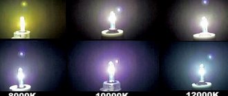
Spectral characteristic It determines in what wavelength range the LED emits, roughly speaking the color of the radiation. Usually the peak wavelength value and a graph of the LED emission intensity versus wavelength are given. I rarely look at this data. I know, for example, that the LED is red and that’s enough for me.
Climatic characteristics They determine the operating temperature range of the LED and the dependence of the LED parameters (direct current and radiation intensity) on temperature. If you plan to use the LED at high or low temperatures, you should pay attention to these characteristics.
The article is intended for beginner electronics engineers, and therefore I deliberately do not touch on the physics of LED operation. Understanding that an LED emits photons as a result of the recombination of charge carriers in the pn junction region does not provide any useful information for the practical use of LEDs. And not only for use, but also for understanding in principle. However, if you want to delve into this topic, then I’ll give you a direction on where to dig - Pasynkov V.V., Chirkin L.K. “Semiconductor devices” or Zi.S “Physics of semiconductor devices”. These are university textbooks - everything there is adult-like. About connecting LEDs in the next article... Shared the article - received an LED beam of goodness!