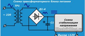
Application
Without the use of decoupling, the maximum current flow between circuits is limited only by electrical resistances, which are usually relatively small. This may result in the flow of equalizing currents and other currents that can damage circuit components or injure people touching equipment that has electrical contact with the circuit. A decoupling device artificially limits the transfer of energy from one circuit to another. An isolation transformer or optocoupler can be used as such a device. In both cases, the circuits are electrically separated, but energy or signals can be transferred between them.
Operation of electromechanical isolation
In addition to those already listed, there is an electromechanical decoupling option. The question of why it is needed practically does not arise, since devices based on this are widely used in electrical engineering.
The basis of such devices is a relay that connects electrical circuits as a result of any changes in input data. As a result, they find themselves decoupled, and the system itself is called relay.
The most striking example is the circuit of an electromagnetic relay. These devices are needed to protect electrical installations and in various automatic systems. They are divided into DC and AC relays. The main element is the armature, which, under the action of an electromagnet and a spring, closes and opens contacts.
Operating principle of a galvanic cell
What is a galvanic cell
Impulse power block
Operating principle of a polarized relay
Current transformers purpose and principle of operation
Solid state relay
Add a link to a discussion of the article on the forum
RadioKot >Schemes >Power supply >Power supplies >
| Article tags: | Add a tag |
Advanced galvanic isolation
Author: igor_sumy Published 02/07/2017 Created with the help of KotoEd.
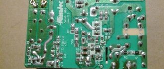
Any cat, if he has to pick up a switching power supply in his paws in order to repair it, always takes a risk. Either the capacitor will take over and give up the ghost, or the transistor will decide to fly off to another world, and other troubles can happen. It has long been known that switching on switching power supplies after repairs through a light bulb allows you to avoid splashes, sparks, odors, etc. Frrrr, as soon as I remember, the hair on my tail stands on end. Experienced cats also strongly recommend using galvanic isolation when repairing SMPS. These switching power supplies are terrible. But the world is such that there are more and more of them and they often have to be repaired. This device is intended just for such cats. It allows you to configure the SMPS through galvanic isolation, run the SMPS through a light bulb and without it, short-term and long-term. I came across the idea for this device in Poland at a service center in a small town. There, a similar device (though with a power of 3 kW) without automation, or rather with automation on a relay, has been in use for many years and I had the opportunity to work with it. Understand how great this idea is. And I decided to do something similar. I limited the power of the transformer to 100 W because I don’t use irons and hair dryers for repair purposes, but for household SMPS this is quite enough. Here's what I got:
The galvanic isolation transformer is connected to the network through a 6A circuit breaker in case something goes completely wrong, it should be knocked out. So far this has not happened. In principle, the machine can be replaced with a regular toggle switch. The original design used a “automatic plug” from the electric meter. Controls: on the left in the photo there is an automatic switch, above it there is a green LED “Ready”, below it is a switch for lamp-barterers, I will talk about it later. Next is a modernized output socket, I’ll also talk about it later, under it is a 3-position switch without locking for short-term supply of voltage to the output. To the right of the socket is a window covered with a red light filter, through which you can see the filaments of the lamps. Under the window there is a red button without locking - a button for turning the device into long-term mode.
To work with this device as follows: 1. Turn on the device automatically, and the “Ready” LED will flash briefly, which indicates that the device is working. In principle, it would not hurt to add another LED to the device to indicate the on state, but the laziness inherent in cats and the complexity of disassembling the structure have not yet allowed this. I decided that I would add an LED when I replaced the burnt out lamp. So, the LED blinked, everything is fine. 2. Remove the switch under the socket from the middle position and supply power to the SMPS through the light bulb (supply 110V to the left, 220V to the right). There is no way to apply voltage without excluding the light bulb from the circuit with this switch. This is done for security reasons. Having applied the voltage, we observe through the window how the barter lamp flashed and almost went out. If so, then everything is fine. You can go to the “red button”, but if the lamp is constantly burning brightly, something is wrong in the SMPS circuit, you should not apply voltage. The method of repairing an SMPS using a light bulb has been described in more detail many times on the Internet 3. Let's move on to the “Red button”; one short press on it will turn on mode 1 . Relay K1 will operate and, with its closing contacts, supply voltage to the output through the lamp, and with its breaking contacts it will break the 110V circuit. This is again done for safety. Because no erroneous manipulations with the device will disable it. Without this contact, one can imagine a situation where relay K1 is triggered and by hooking the switch with its tail, the floor of the secondary winding of the transformer can be short-circuited. Do not disdain this contact if you repeat this device and leave it in 110V mode. In this operating mode (i.e. 220V through a light bulb), the group of blue LEDs at the top of the socket, designated VD7-VD8 in the diagram, will begin to blink at a frequency of about 1 Hz. Pressing the red button again briefly will disable this mode. 4. A long (more than 1 second) press on the “red button” will turn on the K2 relay and the 220V voltage from the secondary winding of the transformer will be supplied to the load, bypassing the barrier lamps. This is mode 2 . In this case, the blue LED display will glow constantly. You can also disable this mode by holding the “red button” for a long time. Or by unplugging the SMPS plug from the socket, I’ll tell you about that later.
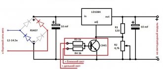
Diagram of the power part of the device
The device has two barter lamps. At 15W and 60W. The first is for repairing low-power SMPS, which are used in phone chargers, etc. The second is for 60 W for repairing SMPS of televisions, amplifiers and other relatively powerful SMPS. The lamp switch is located under the power switch. Unfortunately, it only allows you to add a 60W lamp in parallel to a 15-watt one. This is not entirely logical, but I really wanted to use just such a pull switch from an old telephone exchange. It reminds me so much of the power switch of my first oscilloscope S1-83, which was just turned on by the exhaust switch. Nostalgia happens to cats too. You can use another switch, or better yet, a switch.
Automation block diagram. The automation unit is powered by an additional transformer winding. The AC voltage is 18V. The automation unit is based on this device https://www.drive2.ru/c/292144/ originally intended for a car. I really liked the idea of controlling it with one button. The Polish prototype used separate buttons and a mechanical microswitch in the socket for automatic reset when the load was disconnected. I used an electronic one, on a photo relay (DD1/1, DD1/2 on the circuit diagram). A 1Hz generator is assembled on elements DD1/3 and DD1/4 for blinking the LED panel in mode 1.
Upgraded socket. At the beginning, I wanted to use a mechanical microswitch and bought a wall socket with a curtain and a cover from the Turkish company ViKo for this purpose. However, experiments showed that the cover was not needed at all and only interfered with the work; I carefully cut it off with a Dremel and placed a display of seven bright blue LEDs in its place. The diodes were soldered in series on a strip of breadboard and placed in transparent heat shrink. I covered the display on top with a blue plexiglass filter. The curtain that covers the contacts from children is spring-loaded with a fairly powerful spring, the force of which is not easy to overcome. I would move the device from its place on the table, which is not good. So I decided to make a photo relay. In place of the removed curtain in the socket, I glued a photopair of an AL107 infrared LED and an FD256 photodiode on top of each other. If you look into the right hole of the socket through your phone's digital camera, you can see the glow of the LED. If the photodiode is illuminated by LED light or natural light, transistor VT1 is open and the microcontroller is in the Reset state. If you insert a plug into the socket, transistor VT1 will close, and VT2 will open and the green “Ready” LED will light up. When the power is turned on, the LED flashes briefly due to charging of capacitor C1. The operation of the microcontroller, the program for it, as well as a detailed description of its operation can be found by clicking on the link that I provided above. A beeper from a computer was used as W1. No generator. You can use a small-sized dynamic head. The circuit does not work with a piezo emitter. The sound is useful and brings even such a simple device to life.
The entire automation unit is placed on one breadboard. No printed circuit board was developed. Although, from a photograph, you can transfer the wire “ligature” into a drawing for a printed circuit board. This is at your discretion.
Applied parts. Transformer: ready 220V to 36V. Was rewound. The secondary winding was removed; instead, 944 turns were wound with wire with a diameter of 0.55 mm. Turn to turn, with interlayer insulation. In addition, a winding is wound to power the automation unit. It consists of 75 turns of the same wire. The transformer is impregnated with bakelite varnish of hot drying. Relay. Rootless relays from industrial time relays of the VL-64 series are used. 24V DC relay. Although they work normally on 18V. I also settled on these relays because they have an open electromagnetic system, which allows you to quickly check the condition of the contacts. But the relays were attached to the board. Therefore, I made two adapter boards from fiberglass for attaching the relay. In principle, you may have a different design of both the relay unit and the device as a whole.
Momentary switch (pictured black-brown with screw terminals): from some aircraft equipment, designed for 10A. Exhaust switch - from an old automatic telephone exchange. I do not recommend using it. It is difficult to fasten, and the insulation is not designed for 220V. The remaining components should not raise any questions: the lamp sockets are standard, and the 6A automatic machine too. The power section is installed using a flexible wire with a cross-section of 1.5 mm2.
The device is mounted in a suitable housing. I screwed rubber feet on the bottom so that the device would not slide on the table. It wouldn’t hurt to have a handle on top. The device is quite heavy. Already ordered a pen from China. He's going somewhere. So, the device can still be upgraded. Working with the device is simple and pleasant. No more light bulbs on the table that can burn out the table itself or the paper on it. Everything is neat. The device “purrs” pleasantly when working with the “red button”. In addition, I found the opportunity to quickly check incandescent light bulbs without disassembling the device. To do this, you need to use the “red button” to turn on mode 2 and move the short-term switch to the 110V position. In this case, 110V will be supplied to the light bulb (or group of lamps), and it is easy to verify its serviceability by looking through the window (covered with a red filter) at the filament.
All questions, as usual, in PM, or on the forum if my design needs discussion. PS. I am grateful to the user with the nickname “Veteran’s Scooter” from the site www//http:drive2.ru for designing a device that suited me perfectly. I didn't have to come up with my own version.
All questions in the Forum.
| What do you think of this article? | Did this device work for you? | |
| 61 | 8 | 5 |
Operating principle of capacitive decoupling
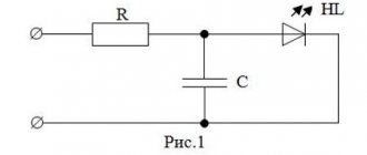
The question often arises as to why different types of decoupling are needed, including capacitive decoupling. This circuit represents a system in which there are no connections between the circuits through current, ground and other elements.
In this case, the transmission of data from electrical circuits is carried out using an alternating electric field. The insulation of the circuits occurs due to the dielectric located between the capacitor plates. The quality of the decoupling capacitor is determined by the properties of the dielectric, the size of the plates and the distance between them. This type of insulation has increased energy efficiency; devices based on it are small in size, capable of transmitting electricity and do not respond to external electromagnetic fields.
Normal operation of devices is ensured by separation of signal and interference frequencies. Thus, the capacitance provides very little resistance to the working signal, but creates a barrier for interference.
Capacitive insulation
Capacitive isolators couple the signal through an isolation barrier, usually made of silicon dioxide. They cannot transmit DC signals, making them suitable for common mode blocking. The signal is converted to digital and then replicated on the other side of the barrier using capacitive coupling.
Capacitive isolator, using capacitive coupling to recreate the signal on the other side of the isolation barrier
Unlike inductive insulation, capacitive insulation is not subject to magnetic interference. High data transfer rates and long service life are the hallmarks of these isolators. Capacitive insulators of different ratings are available for sale, which allows you to provide the proper level of protection against failures and possible short circuits.
Galvanic isolation of optoelectronic type
With the development of high technologies using semiconductor elements, BGRs - galvanic insulation units based on optoelectronic units - are becoming increasingly widespread. They are based on optocouplers, known among electrical engineers as optocouplers made on the basis of diodes, transistors, thyristors and other elements with increased photosensitivity.
The general circuit of the optical part, connecting the data source to the receiver, uses neutral photons as a signal. Thanks to this property, the circuit is decoupled at the input and output, as well as its coordination with the input and output resistances.
When an optoelectronic circuit is used, the receiver has absolutely no influence on the signal source, so the signals can be modulated over a wide frequency range. These devices are compact in size, so they are often used in microelectronics.
The design of the optical pair includes a light emitter, a conducting medium for the light flux, and a receiver that converts light into electrical signals. The resistance at the input and output of the optocoupler is very high, on the order of several million Ohms.
First, the input signal reaches the LED, then in the form of light it reaches the phototransistor through the light guide. At the output of the device, this circuit creates a drop or pulse of the output electric current. As a result, the circuits connected on both sides with the LED and the phototransistor are isolated from each other.
Features of the construction of pulse converters with galvanic isolation. Part 1
Currently, the issues of development, research and creation of special static converters (SC) with galvanic isolation, operating as part of ship electrical power systems and special-purpose products made on the basis of digital technology, are very relevant. Providing high-quality and safe power to ships' electrical equipment poses the challenge of using devices using galvanic isolation.
Galvanic connection is when there is a direct connection of two or more sections of an electrical circuit, and galvanic isolation is, accordingly, such an organization of interaction between sections of electrical circuits in which there is no electrical contact. The use of galvanic isolation is one of the mandatory requirements of the technical specifications for the creation of converter equipment to ensure the safe operation of the equipment. As a rule, in power electronics, transformers for the power part and optocouplers for control are used as decoupling.
The primary winding of the transformer is completely isolated from the secondary, so in principle no currents can arise between them (except in cases of breakdown), although the potential difference in the windings can be very large.
Thus, even if the secondary winding is galvanically connected to the housing and, accordingly, to the ground, no stray currents dangerous to equipment and personnel will arise on the housing (Fig. 1).
Rice. 1. The influence of galvanic isolation on electrical safety
One of the features of the operation of high-frequency transformers is the presence of leakage inductance in the windings, which can be represented in an ideal transformer as a series-connected inductance. And just like in any inductive element, energy accumulation occurs. When the inverter operates and, in particular, when one of the transistors opens, the energy accumulated in the leakage inductance is not transferred to the load, leading to high-voltage surges in the primary winding of the transformer and in the switch. In addition, this energy causes a high-frequency oscillatory process in the circuit consisting of the effective capacitance of the open switch, the inductance of the primary winding and the leakage inductance of the transformer (Fig. 2).
Rice. 2. Transient processes in a transistor
If the peak surge voltage exceeds the breakdown voltage of the switching element, power transistor or diode, this will lead to failure of the entire device. Moreover, high amplitude oscillations cause strong electromagnetic interference.
To limit voltage surges, you can use various limiting (snubber) circuits that allow you to dissipate the energy accumulated in the leakage inductance:
- use of zener diodes (Zener diodes);
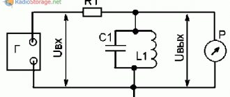
- the simplest snubber (Fig. 3a) is a low-capacity pulse capacitor installed in parallel with the switching element;
- RC snubber to reduce losses in the parasitic oscillatory circuit of the snubber (Fig. 3b);
- RCD snubber for separating the charge and discharge circuits of the capacitor and limiting the discharge current (Fig. 3c);
- active snubber for separating charge limitation and discharge currents through controlled power elements.
Rice. 3. Types of snubbers
Currently, passive C-, RC-, RCD-snubbers and zener diodes are mainly used, but their use is only possible in a relatively narrow power range of converters and power supply equipment from a few watts to 1–2 kW. Although currently in shipbuilding, converter technology of higher power (up to several tens of kilowatts) is required to ensure the operation of individual ship systems. And as has already become clear, creating a pulse converter with galvanic isolation with a power of more than 2–3 kW is not the easiest task. As the power of the converters increases, the current flowing in the windings of the transformer also increases; accordingly, the energy stored in the leakage inductance also increases, and it increases in a quadratic dependence. Consequently, the use of passive snubbers is not possible due to their large dimensions.
The use of an active snubber will help solve this problem. Its peculiarity is that the energy of the pulse (emission) is “pumped” into capacitance C1 and at the moment the key VT1 is opened, it is “downloaded” from the capacitance into the general network, thereby increasing efficiency and saving part of the energy (Fig. 4).
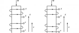
Transformer (inductive) isolation
In order to build inductive isolation, you should use magnetic induction devices - transformers. Its design can be cored or coreless.
Equipping circuits with galvanic isolation of the inductive type is carried out using transformers whose transformation ratio is unity. The primary coil is connected to the signal source, and the secondary coil is connected to the receiver. On this principle, transformer-type galvanic isolations serve as the basis for the creation of magnetic modulation devices.
The output voltage arising in the secondary winding is directly related to the voltage at the input of the transformer device. In this regard, inductive isolation has serious disadvantages, which is why its use is limited:
- It is impossible to manufacture a compact device due to the significant overall dimensions of the transformer.
- The transmission frequency is limited by the frequency modulation of the isolation itself.
- Noise occurring in the input signal reduces the quality of the output signal.
- Such transformer galvanic isolation can only operate normally in the presence of alternating voltage.
Galvanic isolation modules for MGRTP current loop
The modules are designed for galvanic separation of electrical circuits for various purposes. Due to the low conversion error, the modules can be used for galvanic isolation of measuring circuits.
Main advantages Import substitution Technical characteristics Connection diagrams Design and fastening Dimensional drawing Documentation
| Name | Number of channels | Temperature range, °C | Overall dimensions, mm, no more | Price excluding VAT | |
| MGRTP-001 | 1 | -40. +70 | 91x62x6.2 (8.4 - with lid) | 1 914 | |
| MGRTP-011 (formerly LPA-700) | 1 | +5. +60 (without moisture condensation) | 90.4x63x6 (7 - with lid) | 1 465 | |
| MGRTP-002 | 2 | -40. +70 (without moisture condensation) | 120x140x12.5 130x140x12.5 (with terminals) | 2 100 | |
| MGRTP-003 | 3 | -40. +70 (without moisture condensation) | 120x140x12.5 130x140x12.5 (with terminals) | 2 700 | |
Main advantages
Does not require a separate power supply The module does not require separate power supply. For its operation, the module consumes a current not exceeding 1.5 mA from each of the two connected 4.20 mA lines.
Galvanic isolation voltage 1.5 kV Galvanic isolation through optical conversion allows you to protect equipment when operating in conditions associated with the possible influence of electromagnetic influences on it, when it is impossible to ensure high-quality grounding, etc., as well as to ensure the necessary noise immunity when constructing precision measuring systems .
High conversion accuracy The galvanic separation module provides a basic reduced signal conversion error not exceeding 0.1% of the range.
Long warranty period The manufacturer guarantees that the galvanic isolation modules comply with the declared technical characteristics, provided that the consumer complies with the conditions and rules of operation, transportation and storage established in the operational documentation. The warranty period is 48 months from the date of sale.
You can buy galvanic isolation blocks by sending a request by email
Import substitution
Specialists from Lenpromavtomatika LLC recommend using MGRTP-xxx for import substitution of galvanic separation units. Below are the most frequently requested analogues of galvanic isolation modules. To find out what other products can be replaced with MGRTP-xxx, use the “Analogs” .
Technical characteristics of galvanic isolation modules
| External module power supply | not required |
| Current consumption for each connected line | no more than 1.5 mA |
| Input signal | 4..20 mA |
| Output signal | 4..20 mA |
| Input voltage drop | no more than 5 V at a current of 20 mA |
| Output supply voltage | 5..26 V |
| Basic reduced conversion error | no more than 0.1% |
| Galvanic isolation voltage between input and output | not less than 1500 V |
| Average service life | 12 years |
| Mean time between failures | at least 150,000 hours |
Block diagram of MGRTP-001 and MGRTP-011 (formerly LPA-700)
The following designations are used in the diagram: RT - current regulator; PT - current receiver.
Block diagram of MGRTP-002
The following designations are used in the diagram: RT - current regulator; PT - current receiver.
Block diagram of MGRTP-003
The following designations are used in the diagram: RT - current regulator; PT - current receiver.
Recommended connection diagrams
MGRTP-001
Typical connection diagram for galvanic isolation module MGRTP-001
Download the diagram (pdf, 171 KB)
Separate connection diagram for MGRTP-001 modules
Connection diagram for MGRTP-001 modules with signal splitting from one sensor
Mixed connection diagram for MGRTP-001 modules using the example of four galvanic isolation modules when using different connection options in one system
MGRTP-011 (formerly LPA-700)
Typical connection diagram for galvanic isolation module MGRTP-011 (formerly LPA-700)
Download the diagram (pdf, 174 KB)
Separate connection diagram for MGRTP-011 modules (formerly LPA-700)
Connection diagram for MGRTP-011 modules (formerly LPA-700) with signal splitting from one sensor
Mixed connection diagram for MGRTP-011 modules (formerly LPA-700) using the example of four galvanic isolation modules when using different connection options in one system
MGRTP-002
Typical connection diagram for galvanic isolation module MGRTP-002
Download the diagram (pdf, 353 KB)
Separate connection diagram for MGRTP-002 modules
Connection diagram for MGRTP-002 modules with signal splitting from one sensor
MGRTP-003
Typical connection diagram for galvanic isolation module MGRTP-003
Download the diagram (pdf, 447 KB)
Separate connection diagram for MGRTP-003 modules
Connection diagram for MGRTP-003 modules with signal splitting from one sensor
The following designations are used in the connection diagrams: D - sensor. PSU - power supply unit for the primary or secondary measuring transducer. IP - measuring transducer.
Construction and fastening
Structurally, the galvanic isolation modules are made in plastic housings. All MGRTP are installed on a standard 35 mm wide DIN mounting rail. Modules MGRTP-001 and MGRTP-011 have non-removable spring terminals; MGRTP-002(3) modules - removable screw terminals.
Operating principle
Galvanic isolation, according to its function, is also known as galvanic isolation. These systems provide electrical isolation of a specific circuit from other types of circuits nearby. The use of galvanic isolation allows for contactless control and provides reliable protection of people and equipment from electric shock.
Due to its features, galvanic isolation ensures the exchange of signals or energy between circuits, while eliminating direct electrical contact. With its help, an independent signal circuit is formed by forming an independent current circuit of the signal circuit in relation to the current circuits of other circuits.
In order to better understand what galvanic isolation is, we can consider its action using the example of a standard industrial electric motor. In most cases, production uses a supply voltage that significantly exceeds 220 volts and poses a serious danger to operating personnel.
In this regard, current is supplied to the windings and the motor is turned on using special devices that provide switching of power circuits. In turn, the switches are also controlled, most often with on and off buttons. It is in this area that an isolation is required to protect the operator from exposure to dangerous voltage. It does not reach the control panel due to the mechanical interaction of the starter’s structural elements with the magnetic field.
Currently, these systems are used in various technical solutions: inductive, optical, capacitive and electromechanical.
Design and principle of operation
The main difference between an isolation transformer is the absence of galvanic connection between the coils, which are reliably separated by galvanic insulation. Typically, the windings that form the primary circuit of a transformer are identical in parameters to the windings in the secondary circuits. In this case, the transformation ratio for this isolation transformer is equal to 1. That is, the device is used exclusively for galvanic isolation. An example of a separating apparatus is shown in Fig. 1.
Rice. 1. Isolation transformer
A characteristic feature of transformers of this type is that the circuits of the secondary windings in the separating transformation are not equipped with protective grounding. In order to ensure the reliability of galvanic isolation, additional insulation is used between the coils. In some cases, the turns of the primary windings are separated by a protective screen from the secondary windings or physically separated into different parts of the magnetic circuit.
Otherwise, the design and operating principle are no different from other types of transformers:
- the primary winding receives voltage from the network;
- The resulting magnetic induction spreads throughout the entire magnetic circuit.
- The induced emf excites an electric current in the turns of the secondary coil.
There is a relationship between the voltages in the coils and the currents: the values of the secondary voltages are directly proportional to the primary voltages, with a proportionality coefficient k=W2/W1 , and the output current is inversely proportional to the current in the primary winding.
Due to the absence of galvanic connection between the coils and the separation of the primary winding from the ground circuit, accidental contact with any terminal of the secondary coil does not lead to electric shock. You only need to be careful about touching different terminals of the transformer at the same time.
Thus, during electrical contact with live parts of equipment powered from an isolation transformer, an electrical circuit with the ground is not formed, which eliminates the possibility of electric shock. Isolation transformers also provide protection for connected electrical appliances during single-phase faults. If a short circuit occurs in the primary circuit, then the secondary circuit is simply de-energized. However, for complete protection, connect an RCD to the primary circuit.