Designations of switches and switches on electrical diagrams
Conventional graphic symbols of switching products - switches, switches, electromagnetic relays are built on the basis of contact symbols: making (Fig. 1, b), breaking (c, d) and switching (d, f).
Contacts that simultaneously close or open two circuits are designated as shown in Fig. 1, (w, and and). The initial position of the closing contacts on electrical circuits is taken to be the open state of the switched electrical circuit, the breaking contacts are taken to be closed, and the switching contacts are taken to be the position in which one of the circuits is closed and the other is open (with the exception of the contact with the neutral position). The UGO of all contacts can only be depicted in a mirrored or rotated 90° position.
The standardized UGO system also provides for the reflection of such design features as the non-simultaneous operation of one or more contacts in a group, the absence or presence of their fixation in one of the positions.
So, if it is necessary to show that the contact closes or opens earlier than others, the symbol of its moving part is supplemented with a short stroke directed in the direction of operation (Fig. 2, a, b), and if later, with a stroke directed in the opposite direction (Fig. 2, c, d).
The absence of fixation in the closed or open positions (self-return) is indicated by a small triangle, the apex of which is directed towards the initial position of the moving part of the contact (Fig. 2, e, f), and fixation is indicated by a circle on the symbol of its fixed part (Fig. 2, g, And).
The last two UGOs on electrical diagrams are used in cases where it is necessary to show a type of switching product whose contacts usually do not possess these properties.
The conventional graphic designation of switches on electrical diagrams (Fig. 3) is based on the symbols of the making and breaking contacts. This means that the contacts are fixed in both positions, i.e., they do not have self-return.
The letter code of products in this group is determined by the switched circuit and the design of the switch. If the latter is placed in the control, signaling, measurement circuit, it is designated by the Latin letter S, and if in the power circuit - by the letter Q. The control method is reflected in the second letter of the code: push-button switches and switches are designated by the letter B (SB), automatic ones - by the letter F (SF), all others - with the letter A (SA).
If the switch has several contacts, the symbols of their moving parts on the electrical diagrams are placed in parallel and connected by a mechanical connection line. As an example in Fig. Figure 3 shows a conventional graphic designation of switch SA2, containing one break and two make contacts, and SA3, consisting of two make contacts, one of which (right in the figure) closes later than the other.
Switches Q1 and Q2 are used to switch power circuits. The Q2 contacts are mechanically connected to some control, as indicated by the dashed line segment. When depicting contacts in different sections of the circuit, their belonging to one switching product is traditionally reflected in an alphanumeric positional designation (SA 4. 1, SA4.2, SA4.3).
Similarly, based on the symbol of the switching contact, symbolic graphic symbols of two-position switches are built on electrical diagrams (Fig. 4, SA1, SA4). If the switch is fixed not only in the extreme, but also in the middle (neutral) position, the symbol of the moving part of the contact will be placed between the symbols of the fixed parts, the possibility of turning it in both directions is shown by a dot (SA2 in Fig. 4). The same is done if it is necessary to show on the diagram a switch that is fixed only in the middle position (see Fig. 4, SA3).
A distinctive feature of UGO push-button switches and switches is the button symbol connected to the designation of the moving part of the contact by a mechanical connection line (Fig. 5). Moreover, if the conventional graphic designation is based on the main contact symbol (see Fig. 1), this means that the switch (switch) is not fixed in the pressed position (when the button is released, it returns to its original position).
If it is necessary to show fixation, use symbols of contacts with fixation specially designed for this purpose (Fig. 6). Return to the original position when pressing another switch button is shown in this case by the symbol of the locking mechanism, attaching it to the symbol of the moving part of the contact on the side opposite to the button symbol (see Fig. 6, SB1.1, SB 1.2). If the return occurs when the button is pressed again, the sign of the locking mechanism is depicted instead of the mechanical connection line (SB2).
How to Read Automotive Wiring Diagrams
Failure of the electronic components of a modern car can lead to its complete immobilization . It’s good if this happened near your home or work, but if this happens on the highway or in nature, such a breakdown can cost you extremely dearly: both in terms of money, and in terms of lost time and even (I hope it doesn’t come to that) health !
Why is it useful to understand auto electrics?
Even if you are not technically minded or your income allows you not to think about such mundane details, replacing a regular blown fuse on a long journey will make your life much easier.
I'm not even talking about those cases when servicemen, not wanting to understand the problem of your car, urge you to change all the sensors in a row, spending significant amounts of money on this “carousel” (which, by the way, sometimes does not guarantee a positive result).
Therefore, I suggest that you do not give up ahead of time and try to independently diagnose the breakdown of your car, and for this it would be nice to have electrical diagrams on hand, and most importantly, be able to read and understand them.
Electrical circuits? - even a schoolboy can figure it out!
When I first encountered a schematic electrical diagram of a car, I realized that the principles of its construction and the designation of elements on it are standardized, and those elements that are present in all cars are designated the same way, regardless of the car manufacturer. It is enough to figure out once how to read such electrical diagrams, and you can easily understand what is shown on it, even if this is the first time you have seen a specific diagram from a specific car and have never even climbed under the hood of it.
Graphic designations of circuit elements may differ slightly; in addition, there are black and white and color versions. But the letter designation is the same everywhere.
note
In addition to schematic electrical diagrams, it is useful to have diagrams that indicate the physical location (in space) on the body of various harnesses, connectors and grounding points - this will help you quickly find them.
So, let's take a look at examples of such circuits, and then proceed to describe their elements.
An example of a car electrical circuit diagram
The circuit diagram does not indicate the physical relative positions of the elements, but only shows how these elements are connected to each other. It is important to understand that if two elements on such a diagram are shown next to each other, on the body itself they can be in completely different places.
Schematic arrangement of electrical components on the body
Such a diagram carries another type of information: the routing of the cable braids and the approximate location of the connectors on the body.
Three-dimensional accurate diagram of the location of electrical components of the car
There are also diagrams that show exactly how and where the cable routes go in the car body, as well as grounding points.
Standard elements of a car circuit diagram
Let us finally begin to examine the elements of the diagram and learn how to read it.
Standard power circuits and connection of elements
Power circuits - circuit elements that transmit current, are depicted by lines: at the top of the diagram there are circuits with a positive potential (“plus” of the battery), and at the bottom - with a zero potential, i.e. ground (or battery negative).
Circuit 30 - comes from the positive terminal of the battery, 15 - from the battery through the ignition switch - “Ignition 1” Circuit number 31 - grounding
Some wires also have a digital designation at the point of connection to the device; this digital designation allows you to determine where it comes from without tracing the circuit. These designations are combined in the DIN 72552 (frequently used values):
For convenience, connections between elements on color diagrams are depicted in different colors corresponding to the colors of the wires, and on some diagrams the wire cross-section is also indicated. On black and white diagrams, the colors of the connections are indicated by letters:
Sometimes you can find an empty circle in a node - this means that this connection depends on the configuration of the car, and the lines are usually signed.
Designation of connectors on the electrical diagram - connectors
Pin No. 2 of connector C301 is connected to pin No. 9 of connector C104, which, in turn, goes to pin No. 3 of connector C107
Wires in car wiring are connected in several ways, and one of them is connectors.
The connectors are designated by the letter “C” and a serial number. In the figure on the left you see a schematic representation of the connections of sections of wire through connectors.
In general, it is more correct to say not “pin No. 2”, but “terminal No. 2”; if you come across such a concept in the diagram, then now you will know that this is the serial number of the connection (contact) in the connector.
Well, in this figure you can see how the contacts in the connectors are numbered and how to count them correctly in order to find out which pin is which. Contacts are numbered from the “mother” side from the upper corner from left to right line by line. From the “dad’s” side, accordingly, it is mirrored.
By the way, for some reason, on many forums, car connectors are called “tricks”; there is no information on this “etymology” on Google. If you know or guess where this name came from, write in the comments, don’t be shy.
Source: https://artsybashev.ru/cardriver/kak-chitat-elektricheskie-shemi-avtomobilya/
Switches and Switches
Conventional graphic symbols of switching products [4] - switches, switches and electromagnetic relays are built on the basis of contact symbols: making ( Fig. 5.1, b ), breaking (c, d) and switching (d, f). Contacts that simultaneously close or open two circuits are designated as shown in Fig. 5.1 , g, i.
The initial position of the closing contacts is taken to be the open state of the switched electrical circuit, the breaking contacts are taken to be closed, and the switching contacts are taken to be the position in which one of the circuits is closed and the other is open (with the exception of the contact with the neutral position). The UGO of all contacts can only be depicted in a mirrored or rotated 90° position.
The standardized UGO system also provides for the reflection of such design features as the non-simultaneous operation of one or more contacts in a group, the absence or presence of their fixation in one of the positions. So, if it is necessary to show that the contact closes or opens earlier than others, the symbol of its moving part is supplemented with a short stroke directed in the direction of operation ( Fig. 5.2 , a, b), and if later, with a stroke directed in the opposite direction ( Fig. 5.2 , c, d). The absence of fixation in a closed or open position (self-return) is indicated by a small triangle, the apex of which is directed towards the initial position of the moving part of the contact (Fig. 5.2, e, c), and fixation is indicated by a circle on the symbol of its fixed part ( Fig. 5.2 , g, And). The last two UGOs are used in cases where it is necessary to show a type of switching product whose contacts usually do not possess these properties. The conventional graphic designation of switches ( Fig. 5.3 ) is built on the basis of the symbols of making and breaking contacts. This means that the contacts are fixed in both positions, i.e., they do not have self-return.
The letter code of products in this group is determined by the switched circuit and the design of the switch. If the latter is placed in the control, signaling, measurement circuit, it is designated by the Latin letter S, and if in the power circuit - by the letter Q. The control method is reflected in the second letter of the code: push-button switches and switches are designated by the letter B
If the switch has several contacts, the symbols of their moving parts are placed in parallel and connected by a mechanical connection line. As an example in Fig. Figure 5.3 shows the conventional graphic designation of switch SA2, containing one break and two make contacts, and SA3, consisting of two make contacts, one of which (right in the figure) closes later than the other. Switches Q1 and Q2 are used to switch power circuits. The Q2 contacts are mechanically connected to some control, as indicated by the dashed line segment. When depicting contacts in different sections of the circuit, their belonging to the same switching product is traditionally reflected in an alphanumeric positional designation (SA4.1, SA4.2, SA4.3).
General switching diagram and operating principle of the power button
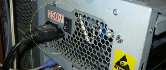
AT-standard personal computers disappeared from the scene back in the 90s. They were turned on by a key on the power supply, which acted as a switch. It directly closed and opened the network power supply circuit of the computer. The current standard is ATX. In accordance with its requirements, starting the PC is ensured by the presence of standby voltage on the motherboard, which appears when the computer is connected to a 220-volt network. And the start command is supplied from a low-current button, which in most cases is installed on the front panel of the PC case. In response to this action, the motherboard generates a Power_ON signal, which allows the power supply to start and provide all the voltage necessary for operation. Pressing it again activates the algorithm for shutting down the computer normally, closing programs and then removing power from the PC components. When pressed for a long time, a reset and restart signal is generated.
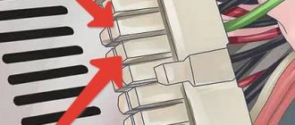
The connection diagram of the power button to the motherboard is generally simple. The switch (with one pair of contacts that closes when pressed) is connected through a cable of two wires to the corresponding pins on the motherboard.
Power button connection diagram.
For this purpose, the board has a mating connector.
Connecting the Power SW connector to the board.
One-letter symbolism of elements
Letter codes corresponding to individual types of elements most widely used in electrical circuits are combined into groups designated by one symbol. Letter designations correspond to GOST 2.710-81. For example, the letter “A” refers to the “Device” group, consisting of lasers, amplifiers, remote control devices and others.
The group denoted by the symbol “B” is deciphered in the same way. It consists of devices that convert non-electrical quantities into electrical ones, which does not include generators and power supplies. This group is complemented by analogue or multi-digit converters, as well as sensors for indications or measurements. The components themselves included in the group are represented by microphones, loudspeakers, sound pickups, ionizing radiation detectors, thermoelectric sensitive elements, etc.
All letter designations corresponding to the most common elements are combined into a special table for ease of use:
The first letter character required to be reflected in the marking
Group of main types of elements and devices
Elements that make up the group (the most typical examples)
A
Lasers, masers, remote control devices, amplifiers.
B
Equipment for converting non-electrical quantities into electrical ones (without generators and power supplies), analogue and multi-charge converters, sensors for indications or measurements