Part 2
Microprocessor-based relay protection devices (MPDs) appeared on the market in their usual form about 20 years ago and have since seriously replaced all other types of protection relays. The triumphant march of MPD is associated with many reasons, the main one of which is the excess profit received by MPD manufacturers compared to the production of all other types of protective relays (electromechanical, semiconductor static). The operating principle and design of modern MPDs are very different from other types of protection and have a number of specific features, knowledge of which is a prerequisite for the correct selection and further successful operation of MPDs. The dominant attitude today among relay specialists towards MPDs as a “black box” with relay protection functions does not at all contribute to the correct selection and successful operation of MPDs. The proposed series of articles by the author is intended to help relay engineers who are not specialists in the field of electronics and microprocessor technology, fill the existing gap and help correctly navigate the vast market of new generation relay protection devices.
Part 1 of the article discusses the general structure and design of the MPD, as well as the design of analog inputs.
General structure and design of MPD
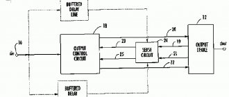
The main components of the MPD are: a block of analog inputs (current and voltage transformers), input filters (anti-aliasing filters; sampling and storing circuits), a multiplexer, an analog-to-digital converter, a microprocessor, various types of memory, a block of logical (digital) inputs, a block of relay outputs , rice. 1.
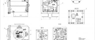
Structurally, MPDs are a set of flat modules (printed circuit boards) representing various functional units of MPDs, housed in housings of various types and sizes, Fig. 2.
There are several design diagrams for the arrangement of printed circuit boards in MPD housings. One of such design schemes is the so-called “stack module”, which involves the arrangement of printed circuit boards one above the other. The boards are fastened together with threaded bushings, forming a single structural module, similar to a bookcase, Fig. 3.
This module is then installed inside the MPD housing. The connection between the boards is made through connectors and a flat flexible cable. The obvious disadvantage of this design is the impossibility of replacing a separate module without dismantling and disassembling the entire MPD.
Another type of MPD design is an “open cube” type housing, Fig. 4. In this design, three printed circuit boards form the side and rear walls, fastened together with special corner connectors and attached to a metal faceplate, which is the fourth wall.
After assembly, this entire structure is inserted into the outer casing.
The most widespread design is with retractable boards, which has many varieties, Fig. 5.
A design of this type contains an aluminum housing with guides along which individual (modules) printed circuit boards, which make up the MPD, are pushed into it.
The boards can be placed vertically or horizontally in the case. Another additional board (the so-called “motherboard”) with a set of connectors is located at the bottom of this case. When the boards are pushed along the guides into the MPD housing, the connectors protruding from them enter the mating parts of the connectors located on the motherboard and, thus, a connection is made between the boards.
The MPD uses three types of boards, which provide interconnection of all other boards. In the first case, it can be a motherboard, on which, in addition to a set of connectors, there is also a microprocessor, an ADC, various types of memory and all the accompanying elements (Fig. 6b). In the second case, it can be a separate rigid board with a set of connectors (Fig. 6a), or, in the third case, a flexible flat multi-core cable with connectors connecting the boards to each other (Fig. 6c). Connection boards of the last two types are also sometimes called “backplanes”.
In some not very successful designs, Fig. 7 you have to remove several modules at once in order to get to the module with the power supply. And in order to extend this module to replace the power supply, you need to unsolder the leads of all current transformers from the terminal block on the rear panel, and then solder them again.
Relays of the T60 type have a rather strange design, Fig. 8. Relays of this type consist of separate plug-in modules located in a common housing. Unlike all other MPDs, in the T60 each module is placed in a steel casing, which is why the relay turned out to be heavy (15 kilograms, no less).
After opening the casing, what remains is a printed circuit board with a powerful connector at the end. This connector has a very strange design and is equipped with a large plastic casing, divided into large cells, inside which are located electronic components, output relays, varistors, Fig. 9.
This cover is secured to the connector using 8 plastic latches, 4 on each side, which must open at the same time. An attempt to open this casing immediately resulted in the breaking of one of the latches, after which my attempts were stopped. This plastic casing does not carry any functional load and, in my opinion, its only purpose is to make the relay irreparable.
This type of MPD is equipped with both conventional electromechanical and semiconductor output relays, and, as indicated in its description (T60 Revision: 5.6x), the semiconductor output relays are equipped with special circuits “for monitoring the constant voltage on open contacts and the direct current flowing through closed contacts". As if everything was clear and understandable... But what was written next puzzled me: “The voltage is written as a logical unit when the current in the contact circuit exceeds 1-2.5 mA and the current is considered a logical unit when it exceeds 80- 100 mA.” It’s hard to even imagine a stranger (to put it mildly) explanation. This strangeness is not only in the text, but also in the essence of the technical solution. Firstly, monitoring is only possible with direct current, which limits its scope of application. Secondly, the load current can be very small (1-3 mA), for example, the logical input current of another MPD, or sensitive electromechanical intermediate relays. How will the current monitoring system work in this case? It turns out that the developers of this system took this possibility into account and offer consumers to connect an additional external resistor in parallel with the contacts. For a voltage of 48 V, it is recommended to choose this resistor with a resistance of 500 Ohms and a power of 10 W. That's a pretty big resistor! Can you imagine what this resistor should be like for a voltage of 220 V? And where should I install it? The T60 developers are modestly silent about this...
Another “invention”: automatic cleaning of contacts (autho-burnishing) of external relays that supply signals to the T60 logic inputs. The designers were concerned that with very low input currents of logical inputs (less than 3 mA) and oxidized contacts of external relays, the signal may not “pass” through them. To self-clean these contacts, the T60 has special nonlinear elements installed at the inputs (obviously, something like posistors), which have low resistance in a de-energized (cold) state and quickly increase resistance when voltage is applied to them (and temperature rises). As a result, at the first moment after the contacts of the external relay are closed, a current of 50-70 mA passes through them, which quickly decreases (within 25-50 ms) to 3 mA. Seems like a nice idea. But this is only for those who are not very well versed in contact processes. “Obstruction” of contacts as a result of their oxidation occurs in low-current circuits with a switching voltage below 20-30 V. At higher voltages, breakdown of very thin oxide films occurs and contacts, which look black and unsightly, conduct even small currents perfectly (phreaking effect ). Therefore, for real MPD operating voltages, this problem is completely far-fetched, and its technical implementation is completely meaningless.
Product description
CURRENT PROTECTION DEVICE RS83-A2M
Protection and automation functions
| Function name | Number of steps |
| Maximum current protection (overcurrent protection) | 4 |
| Directional/non-directional earth fault protection (GC) | 2 |
| Negative sequence current protection (NSP) | 2 |
| External protections (EP) or signals triggered via discrete inputs | up to 14 |
| Arc protection with fiber optic sensor and current blocking | 0-2 |
| Automatic reclosing (AR) | 2 |
| AFR-CHAPV (via discrete input) | 1/1 |
| Level of failure | 1 |
| Automation and circuit breaker control | 1 |
| Power supply via current circuits | Optional |
| Built-in deshunting | Optional |
| Setting groups | 2 |
| Interfaces RS-485, USB | 2 |
Main technical characteristics of the device
| Parameter name | Meaning |
| Rated current, A | 5 |
| Rated circuit voltage 3U0, V | 100 |
| Rated supply voltage, polarity arbitrary (~/=), V | 220 (110) |
| Rated network frequency, Hz | 50 |
| Ready time when powered from current circuits, no more, ms | 150 |
| Range of overcurrent and low-voltage protection settings for rated current, A (secondary) | 1-120 |
| Range of ZNC settings for measured current, by version, A | 0,004-1; 0,02-5; 1-120 |
| Operating range of device supply voltage, continuous ~/ =, V | 80-264 |
| Permissible increase in supply voltage for up to 5 minutes, V | 420 |
| Consumption on power circuits when the output relays do not operate, W | 10 |
| Increase in consumption when the relay is activated, W/relay | 0,25 |
| Operating temperature range, °C | from -40 to +70 |
| Number of digital inputs | 8-18 |
| Number of output relays | 8-16 |
Device Features
- For any stage of the MTZ, operation with independent or with any of 7 types of dependent ampere-second characteristics can be assigned.
- For any stage of the overcurrent protection, blocking at the 2nd harmonic of the current can be entered or removed, which allows you to tune out the inrush of the magnetizing current when the switch is turned on.
- Each of the ZNC stages can be assigned to operate according to the measured or calculated current 3Iо.
- When operating on the measured current 3Iо, the setting range for the ground fault current can be from 0.004 A (secondary value) to ensure high sensitivity in a network with low ground fault currents.
- When operating at a rated current of 3Iо, the range of the ZNC settings can be up to 120 A (secondary value), for operation in a network with large ground fault currents (solidly grounded neutral).
- For any ZNC stage, a voltage trigger can be enabled/disabled (voltmeter blocking).
Advantages
- Extended range of permissible supply voltages ~/= from 80 to 420 V (up to 5 min.).
- Extended operating temperature range from -40°С to +70°С
- Low power consumption, from 10 W.
- High degree of device protection on the front panel, IP54.
- Built-in power supply via current circuits and de-shunting.
- Fast cold start via current circuits from 150 ms.
- Built-in arc protection function.
- Built-in source for guaranteed power supply of discrete inputs.
- High maintainability due to a modular design with easily replaceable unified modules for devices for various purposes.
Technical documentation
- Operating manual RS83-A2M.
- Settings form RS83-A2M;
- Modbus-RTU memory card PC83-A2M;
- RS83-A2M test protocols.
- Connection diagrams.
- Typical relay protection circuits in which RS83-A2M is used.
Software
- CODIS software for PC83-A2M terminal configuration.
- ComTradeViewer software for viewing waveforms in COMTRADE format recorded by the PC83-A2M terminal.
Analog input modules
The simplest DPR modules are analog input modules, consisting of a set of current and voltage transformers, Fig. 10.
The design of voltage transformers is no different from the design of conventional low-power transformers. Current transformers contain an insulated multi-turn secondary winding wound on a frame and covered with an insulating film. The primary winding consists of several turns (usually 5 turns for a rated primary current of 1 A and 1 turn for a rated current of 5 A), wound over the secondary winding with ordinary stranded insulated mounting wire, Fig. 10. Such a transformer is, in fact, a current-to-voltage converter. If during the operation of a MPD there is a need to change the input rated current of the analog inputs from 1 A to 5 A (or vice versa), then this can be done very simply by winding (or, conversely, winding) several turns of wire. This MPD unit usually does not create any operational problems and is its most reliable part.
In most types of MPD, this set of transformers is made in the form of a separate module, although there are also designs in which input filters, analog-to-digital converters, and other elements of pre-processing of analog signals are located in the same module, Fig. eleven.
In some types of MPD you can find miniature toroidal current and voltage transformers encapsulated with epoxy compound, Fig. 12. This design is better protected from moisture, but heat removal is difficult. In addition, it is non-repairable and it is not possible to change the transformation ratio. It should be borne in mind that despite the apparent higher reliability of such a design, its actual operational reliability may be even lower than that of a conventional non-encapsulated transformer. This is due not only to difficult heat removal, but also to internal mechanical stresses in the windings that arise during the curing and shrinkage of the epoxy compound. Problems of this kind usually appear in the presence of multi-turn windings wound with thin wire (as in voltage transformers).
V. GUREVICH, Ph.D. tech. sciences
CPU module
The main module of the MPD, often called the CPU Module, is the most complex, most expensive and most saturated printed circuit board, Fig. 27, made using surface mount technology (SMD technology), on which are located: a microprocessor, memory elements, an ADC, a multiplexer, auxiliary (peripheral) microprocessors, a communication controller, a communication port, etc.
Over the decade and a half that has passed since the release of the 316 series relay, the design of the main module with a central processor has not undergone fundamental changes, Fig. 28. Only the smaller size of the main microprocessor and accompanying functional elements and their smaller number are noticeable to the eye. This is due to the progress of recent years in the field of nanotechnology, which has led to a significant reduction in the size of semiconductor elements (we are talking about units and even fractions of a micron), a decrease in the thickness of layers of semiconductor and insulating materials, a decrease in operating voltages, an increase in operating speed, and an increase in the density of elementary logic cells. in one device.
All this taken together has led to a sharp increase in the sensitivity of semiconductor elements, especially memory cells, to ionizing radiation. This sensitivity has become so high that the usual (that is, completely normal) background radiation at sea level has become dangerous for memory cells.
Streams of high-energy elementary particles coming from space are especially dangerous. Even one such particle, when it enters a memory cell, gives rise to secondary flows of electrons and ions, causing spontaneous switching of an elementary transistor or discharge of capacitance in elements with charge memory. The problem is aggravated by the fact that in modern microprocessor structures there is a steady tendency to expand the use of memory elements.
Many modern high-level integrated circuits that are part of a microprocessor device contain built-in memory elements of a fairly large volume, the serviceability of which is not controlled at all. In recent years, the problem of a sharp increase in sensitivity to ionizing radiation has become relevant not only for memory elements, but also for high-speed logic elements, comparators, etc., that is, for practically all modern microelectronics.
In addition to ionizing radiation, intentional high-frequency electromagnetic radiation, used in many types of modern electromagnetic weapons, is becoming increasingly dangerous for all modern microelectronics.
Microprocessor terminals for protection and automation ABB
Functionality, advantages of microprocessor protection terminals compared to electromechanical protective devices
Equipment of substation switchgears, in particular outgoing lines feeding consumers or adjacent substations, must have reliable protection from possible damage. Up until the 2000s. to protect equipment at substations, they used exclusively relay protection and automation devices of the electromechanical type, which are built on relays of the electromechanical operating principle.
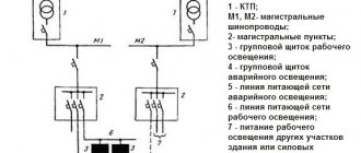
Now old electromechanical protections are gradually being replaced by modern devices - microprocessor terminals for protection, control and automation of equipment, which are increasingly found in newly built or technically re-equipped substations. In this article, we will consider the functionality and advantages of microprocessor protection terminals using the example of using the REF 630 terminal manufactured by ABB to protect a consumer line with a voltage of 35 kV, and provide a comparative description with their predecessors - electromechanical type protections.
Advantages of modern relay protection and automation devices
One of the main advantages of microprocessor terminals over old-style protections is their compactness. To implement protection, automation, and control of 35 kV line equipment, it is necessary to install a complex circuit of many electromechanical relays that barely fit on one relay panel.
In addition, for each line it is necessary to install a switch control key, switches for selecting operating modes, overlays for switching/disabling automatic devices, measuring instruments for recording the load current along the line - for the listed elements you need to install another panel.
The microprocessor protection terminal has small overall dimensions.
Due to its small overall size, one relay protection and automation panel can accommodate two protection terminals and the corresponding keys for controlling 35 kV line switches, as well as for switching various operating modes of relay protection and automation devices.
In this example, the REF 630 protection terminal provides protection for the outgoing power line. The terminal also has other standard configurations that allow the terminal to be used to protect a power transformer, busbar or busbar circuit breaker.
The huge advantage of this device is that standard configurations can be configured with maximum precision for real conditions, all possible nuances can be taken into account, and the necessary functions can be selected.
As for measuring instruments, if microprocessor protection terminals are used, they do not need to be installed, since the phase-by-phase load of the line, as well as other electrical parameters, are displayed on the display of the protective device.
As can be seen in the photo, on the display of the protection terminal, in addition to the load on this line, a mnemonic diagram is displayed indicating the actual position of the switching devices: bus disconnectors from 1 and 2 of the 35 kV bus system, a vacuum circuit breaker, a linear connection disconnector, as well as the position of the stationary grounding devices of the bus and line disconnectors. The display also shows the voltage across the bus system from which the line is currently powered.
If necessary, the protection terminal can be configured to display other measured values (phase voltage, active and reactive components of the load, its direction, frequency of the electrical network) and indicate various operating modes (status of the autorecloser set, autorecloser, partial autorecloser, LZSh).
Also, a significant advantage of microprocessor protection is the ease of control over the operating mode of the equipment, including the elimination of emergency situations. On the front panel of the terminal there are LED indicators indicating their names.
In old-style protections, signal relays, so-called “blinkers,” were used to indicate operating modes. In the event of an emergency or deviations from the normal operation of protective devices, it is necessary to review each of the indicating relays, which very often had an inconvenient relative position, and each of the relays must be returned to its original position (“acknowledged”) individually.
On the protection terminal, the LEDs are arranged in one column, so it is quite convenient to record possible deviations - you just have to look at the corresponding terminal. Another advantage is that to “acknowledge” the LEDs on the terminal, you only need to press one button.
This advantage is most appreciated in the event of a major accident at a substation, when many protective devices are triggered. In this case, it is enough to go to each terminal, fix the position of the LEDs and press the button. For electromechanical protections, it is necessary to spend significantly more time in order to fix the position of each indicating relay and return it to its original position, that is, “acknowledge”.
Functional features of microprocessor relay protection devices
If microprocessor devices are used to protect the line, then in the event of a circuit breaker being disconnected from the protection or in the case of automatic operation, the device memory records the response time, the name of the triggered protection or element of the line automation, and also provides electrical parameters in the pre-emergency, emergency and post-emergency periods. Thanks to this functionality, it is possible to accurately restore the picture of what happened, which is very important in the event of major accidents or accidents in the energy sector.
In the photo you can see that emergency situations are recorded down to milliseconds. This allows, when analyzing the operation of protective devices, to correctly determine the order of their operation and draw a conclusion about the correct operation of the protections in accordance with the specified settings and conditions of their operation.
The device allows you to store 1000 event records in non-volatile memory.
The protection terminal has a self-diagnosis function, monitoring incoming and outgoing circuits, which allows timely detection of a malfunction. When using electromechanical protections, violations in the operation of protective devices are not signaled, so a violation of their operation is very often detected in the event of incorrect operation of the protection or its complete failure.
As for the protection activation settings, in the microprocessor protective device they are changed in the menu by selecting the required values. In this case, you can create several groups of settings and quickly switch between them, which is very convenient if it becomes necessary to temporarily change the settings.
Also, one of the advantages of microprocessor terminals is the ability to connect them to the SCADA system, which allows substation maintenance personnel to monitor the condition of switching devices, the magnitude of loads and voltages on the buses; as well as to the ASDU system, which allows you not only to monitor, but to control equipment remotely, from a central control center.
Relay protection cabinets
Modern microprocessor-based relay protection devices perform not only their direct protection tasks, but also other related functions. Thus, today a large number of devices can be equipped in one cabinet, which greatly simplifies the installation of equipment, direct operation, and also significantly frees up space.
Standard protection cabinets have a number of additional advantages: since the cabinets are made according to standard designs that have been tested in operation, the likelihood of errors in operation is significantly reduced, and the ease of commissioning and installation increases. Find out even more about relay protection and standard solutions on our website.