20/03/19
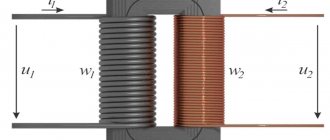
A transformer is needed to increase or decrease the AC current values. Its main parts are input and output (sometimes 1) coils located on a magnetic core. The operation of the device consists of a 2-way change in the magnetic field induced by alternating current. When using DC current, it must first be converted. Alternating voltage is supplied from outside to the primary winding. An alternating voltage is generated on the secondary coils following it. Transformers come in different types and are made from different materials. The shape is determined by the ease of placement of the transducer in the device body. Rated power depends on the type and material of the core. Depending on the characteristics of the core and differences in the number of turns, the transmission coefficient varies.
Possible faults
Common transformer failures include:
- burnout of the cable in the reel;
- insulation damage causing turn-to-turn short circuit or electrical contact between the coil and the housing;
- core defect;
- natural wear of winding terminals or contacts.
A visual inspection of the transformer can reveal damaged or missing insulation, faulty terminals and bolts, swelling or leaking. Also, during inspection, you need to pay attention to the presence of blackness, charring of the paper, and a burning smell. If there is no visible damage, the functionality of the device will be checked using measuring instruments.
Why is comprehensive diagnostics of transformers needed?
To assess the technical condition of electrical equipment, engineering specialists perform comprehensive diagnostics of transformers. With its help, you can identify potential threats and defects that could lead to an accident at a power facility. Based on the data obtained, a concept is being developed to extend the service life of equipment by replacing worn-out working units. A comprehensive examination of transformers is performed in the following cases:
- there is an urgent need for a major overhaul of electrical equipment;
- it is necessary to draw up an expert technical report in case of emergency shutdown of equipment;
- for technical substantiation of identified defects during various types of inspections;
- to determine the conditions and standards for the operation of equipment in accordance with State Industry Standard 11677.
Timely inspection of power transformers reduces the risk of downtime due to emergency stops and increases the reliability of operation of the entire energy facility.
Methods for diagnosing power transformers
The list of diagnostic procedures includes the following work:
- checking the condition of the winding and its insulators;
- checking the characteristics of transformer oil;
- switch diagnostics;
- checking the ventilation system.
Inspection and testing of power voltage transformers begins with examining the condition of the winding.
| Power and voltage class of the high voltage winding (HV) | Temperature in C | |||||
| 10 | 20. | 30 | 40 | 50 | |||
| Up to 35 kV inclusive with a power of less than 10 MVA | D S/S ratio at the end of the audit in % | 13 | 20 | 30 | 45 | 75 |
| The difference between the value of A C/C at the end and beginning of the audit in % | 4 | 6 | 9 | 13,5 | 22 | |
| Transformer power and voltage class of HV winding | in % AT winding temperature in e C | ||||||
| 10 | 20 | 30 | 40 | 50 | 60 | | 70 | |
| Up to 35 kV inclusive with a power of less than 2,500 kVA | 1,5 | 2 | 2,6 | 3,4 | 4,6 | 6 | 8 |
| Up to 35 kV inclusive with a power of less than 10,000 kVA | 1,2 | 1,5 | 2 | 2,6 | 3,4 | 4,5 | 6 |
Diagnostic procedures can detect radiological interference as well as the presence of moisture in transformer oil. After turning off the equipment, engineering experts measure current resistance, insulation resistance and determine loss coefficients. Checking the secondary circuits of voltage transformers is carried out according to the manufacturer's instructions.
| Transformer insulation type | Test voltage in V at rated winding voltage in kV | ||||||
| up to 0.525 | 3 | 6 | 10 | 15 | 20 | 30 | |
| Normal. | 5 | 18 | 25 | 35 | 45 | 55 | 85 |
| Lightweight. | 3 | 10 | 16 | 24 | 37 | ||
The next step is to examine the performance characteristics of transformer oil: color, viscosity, tension, density, insulation resistance, the presence of impurities (moisture, gases) in it. During diagnostics, insulation indicators and grounding quality are measured. The technicians also pay attention to checking the stability of the contact in the switch, measuring its temperature and the number of kV of the electric motor. The parameters that are studied in the ventilation system are the following:
- air flow quality;
- vibrations in bearings;
- indicators of current in the winding;
- cleanliness of surfaces.
To determine the degree of wear of the insulating material, methods such as identifying the degree of concentration of furfural derivatives, carbon oxide and carbon dioxide, and measuring the degree of polymerization are used. Based on the data, the maximum permissible time for further operation of the insulating material is determined. The frequency of inspections of transformers depends on their purposes: the current one is carried out at least once a month. A comprehensive check with measuring instruments for the purpose of subsequent major repairs of technical equipment is carried out every 3-4 years.
Basic information about transformers
To convert alternating voltage ratings, special electrical machines—transformers—are used.
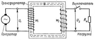
A transformer is an electromagnetic device designed to convert alternating voltage and current of one magnitude into alternating current and voltage of another magnitude.
Device and principle of operation
It is used in all consumer power supply schemes, as well as for transmitting electricity over long distances. The transformer design is quite primitive:
- The ferromagnetic core is made of a ferromagnetic material and is called a magnetic core. Ferromagnets are substances that have spontaneous magnetization; the parameters (atoms have constant spin or orbital magnetic moments) vary greatly due to the magnetic field and temperature.
- Windings: primary (mains voltage is connected) and secondary (power supply to a consumer or group of consumers). There can be more than 2 secondary windings.
- Additional components are used for power transformers: coolers, gas relays, temperature indicators, moisture absorbers, current transformers, protection systems and continuous oil regeneration.
The principle of operation is based on the conductor being in an alternating electric field. When a conductor moves, for example, a solenoid (coil with a core), a voltage can be removed at its terminals, which depends directly proportionally to the number of turns. This approach is implemented in a transformer, but it is not the conductor that moves, but the electric field formed by alternating current. It moves along a magnetic circuit made of ferromagnet. Ferromagnetic is a special alloy ideal for the manufacture of transformers. Basic materials for cores:
- Electrical steel contains a large mass fraction of silicon (Si) and is combined under high temperature with carbon, the mass fraction of which is no more than 1%. Ferromagnetic properties are not clearly expressed, and eddy current losses (Foucault currents) occur. Losses increase directly proportionally with increasing frequency. To solve this problem, Si is added to carbon steel (E42, E43, E320, E330, E340, E350, E360). The abbreviation E42 stands for: E - electrical steel containing 4% - Si with 2% magnetic losses.
- Permalloy is a type of alloy and its constituent parts are nickel and iron. This species is characterized by a high value of magnetic permeability. Used in low-power transformers.
When current flows through the primary winding (I), a magnetic flux F is formed in its turns, which propagates along the magnetic circuit to winding II, as a result of which an EMF (electromotive force) is formed in it. The device can operate in 2 modes: load and idle.
Transformation coefficient and its calculation
Transformation ratio (k) is a very important characteristic. Thanks to it, you can identify malfunctions. The transformation ratio is a value showing the ratio of the number of turns of winding I to the number of turns of winding II. According to k, transformers are:
- Decreasing (k > 1).
- Raising (k
How to check the operation of a transformer with a multimeter
You can diagnose the serviceability of the converter with a multimeter. The diagnostic sequence is as follows: 1. Determination of windings. The converter usually has markings indicating the numbers and type of pins. Using the designations, you can obtain additional information from reference books. For converters installed in electronic devices, you can use device diagrams and detailed specifications. 2. Using a tester. It allows you to identify 2 typical problems - a broken winding and a short to a nearby winding or housing. 3. If there is a suspicion of a winding break, ring all of them one by one with an ohmmeter. The break is confirmed by a resistance equal to infinity. For measurements, it is better to use an analog ohmmeter, since a digital one can distort the readings due to significant induction values. This is most relevant for coils with many turns. 4. Monitoring a short circuit to the housing - 1 probe contacts the winding terminal, and the 2nd probe rings the terminals of the remaining windings and the housing. The contact area on the body is cleared of paintwork in advance.
How to check a pulse transformer for interturn short circuit and open circuit
To check the integrity of the windings, it is best to use a digital tester, but you can also examine them using a pointer tester.
In the first case, the diode testing mode is used, indicated on the multimeter by the diode designation symbol in the diagram.
diode on the diagram
- To determine a break, test leads are connected to the digital device.
- One is inserted into the connectors marked V/Ω, and the second is inserted into COM.
- The roller switch is moved to the dialing area.
- The measuring probes are sequentially touched to each winding, red to one of its terminals, and black to the other. If it is intact, the multimeter will beep.
An analog tester performs the test in resistance measurement mode. To do this, the tester selects the smallest resistance measurement range. This can be implemented through buttons or a switch. The probes of the device, as in the case of a digital multimeter, touch the beginning and end of the winding. If it is damaged, the arrow will remain in place and will not deviate.
In the same way, interturn and short circuits are checked.
A short circuit may occur due to an insulation breakdown. As a result, the winding resistance will decrease, which will lead to redistribution of the magnetic flux in the device.
To carry out testing, the multimeter switches to resistance testing mode.
By touching the windings with probes, they look at the result on a digital display or on a scale (arrow deflection).
This result should not be less than 10 ohms.
To make sure that there is no short circuit on the magnetic circuit, touch the “hardware” of the transformer with one probe, and touch the second one sequentially to each winding. There should be no deviation of the arrow or appearance of a sound signal. It is worth noting that the interturn short circuit can only be measured with a tester in an approximate form, since the error of the device is quite high.
Detection of inter-turn short circuit
To identify such a defect in a pulse transformer, a multimeter is not enough. At a minimum, you will also need good eyesight and attentiveness. To insulate the wire, only its varnish coating is used. In the event of an insulation breakdown, resistance remains between adjacent turns, and the contact area heats up. Therefore, you need to make sure there are no leaks, swelling, burning smell, blackness, or burning. After determining the type of converter, you can see the resistance value of its coils in the reference book. After this, you should use a tester in the megohmmeter functionality to measure the insulation resistance - between pairs of windings and separately between each of them and the housing. Measurements are carried out at the voltage indicated in the technical documentation for the converter. The measured values are compared with the reference values, and if there is a discrepancy of 50% or higher, a winding fault is diagnosed.
Preparation and testing
To check the operation of a pulse transformer, you can use both an analog and digital multimeter. The use of the second is preferable due to its ease of use. The essence of preparing a digital tester comes down to checking the battery and test leads. At the same time, the pointer-type device is additionally adjusted to this.
The analog device is configured by switching the operating mode to the area of measuring the minimum possible resistance. Afterwards, two wires are inserted into the tester sockets and short-circuited. Using a special construction handle, the position of the arrow is set opposite zero. If the arrow cannot be set to zero, then this indicates discharged batteries that will need to be replaced.
It's easier with a digital multimeter. Its design uses an analyzer that monitors the condition of the battery and, if its parameters deteriorate, displays a message on the tester screen indicating that it needs to be replaced.
When checking transformer parameters, two fundamentally different approaches are used. The first is to assess the serviceability directly in the circuit, and the second - autonomously from it. But it is important to understand that if the IT is not removed from the circuit, or at least a number of pins are not disconnected, then the measurement error can be very large. This is due to other radioelements that shunt the input and output of the device.
Procedure for identifying defects
An important step in checking a transformer with a multimeter is identifying the windings. However, their direction does not play a significant role. This can be done using the markings on the device. Usually a certain code is indicated on the transformer.
In some cases, a diagram of the location of the windings or even their conclusions may be marked on the IT. If the transformer is installed in the device, then a circuit diagram or specification will help in finding the pinout. Also often the designations of the windings, namely the voltage and the common terminal, are signed on the PCB itself near the connectors to which the device is connected.
Once the conclusions have been determined, you can proceed directly to testing the transformer. The list of malfunctions that may occur in the device is limited to four points:
- core damage;
- burnt out contact;
- insulation breakdown leading to an interturn or frame short circuit;
- wire break.
The verification sequence is reduced to an initial external inspection of the transformer. It is carefully checked for blackening, chips, and odor. If no obvious damage is detected, then proceed to measurement with a multimeter.
To check the integrity of the windings, it is best to use a digital tester, but you can also examine them using a pointer tester. In the first case, the diode testing mode is used, indicated on the multimeter by the symbol -|>| —))). To determine a break, test leads are connected to the digital device. One is inserted into the connectors marked V/Ω, and the second is inserted into COM. The roller switch is moved to the dialing area. The measuring probes are sequentially touched to each winding, red to one of its terminals, and black to the other. If it is intact, the multimeter will beep.
An analog tester performs the test in resistance measurement mode. To do this, the tester selects the smallest resistance measurement range. This can be implemented through buttons or a switch. The probes of the device, as in the case of a digital multimeter, touch the beginning and end of the winding. If it is damaged, the arrow will remain in place and will not deviate.
The same procedure is used to check for short circuits. A short circuit may occur due to an insulation breakdown. As a result, the winding resistance will decrease, which will lead to redistribution of the magnetic flux in the device. To carry out testing, the multimeter switches to resistance testing mode. By touching the windings with probes, they look at the result on a digital display or on a scale (arrow deflection). This result should not be less than 10 ohms.
To make sure that there is no short circuit on the magnetic circuit, touch the “hardware” of the transformer with one probe, and touch the second one sequentially to each winding. There should be no deviation of the arrow or appearance of a sound signal. It is worth noting that the interturn short circuit can only be measured with a tester in an approximate form, since the error of the device is quite high.
Voltage and current measurements
If a transformer is suspected of malfunctioning, testing can be carried out without completely disconnecting it from the circuit. This testing method is called direct, but is associated with the risk of electric shock. The essence of current measurement is to perform the following steps:
- one of the legs of the secondary winding is unsoldered from the circuit;
- the black wire is inserted into the COM socket of the multimeter, and the red wire is connected to the connector marked with the letter A;
- The device switch is moved to the position corresponding to the ACA zone.
- The probe connected to the red wire touches the free leg, and the black wire touches the place to which it was soldered.
When voltage is applied, if the transformer is operational, a current will begin to flow through it, the value of which can be seen on the tester screen. If IT has several secondary windings, then the current strength is checked on each of them.
The voltage measurement is as follows. The circuit with the transformer installed is connected to the power source, and then the tester switches to the ACV (alternating signal) region. The wire plugs are inserted into the V/Ω and COM sockets
and touch the beginning and end of the winding. If the IT is normal, the result will be displayed on the screen.
Removing characteristics
To be able to check a transformer with a multimeter using this method, its current-voltage characteristic is necessary. This graph shows the relationship between the potential difference at the terminals of the secondary windings and the current strength leading to their magnetization.
The essence of the method is as follows: the transformer is removed from the circuit, and pulses of different sizes are applied to its secondary winding using a generator. The power supplied to the coil must be sufficient to saturate the magnetic circuit. Each time the pulse changes, the current in the coil and the voltage at the output of the source are measured, and the magnetic circuit is demagnetized. To do this, after removing the voltage, the current in the winding increases in several approaches, after which it decreases to zero.
As the current-voltage characteristic is taken, its real characteristic is compared with the reference one. A decrease in its slope indicates the appearance of an interturn short circuit in the transformer. It is important to note that to plot the current-voltage characteristic it is necessary to use a multimeter with an electrodynamic head (pointer).
Thus, using a regular multimeter, you can with a high degree of probability determine the performance of IT
, but for this it is best to perform a set of measurements. Although, to correctly interpret the result, you should understand the operating principle of the device and imagine what processes occur in it, but in principle, for successful measurement it is enough just to be able to switch the device to different modes.
Drive frequency range:
LF power transformers: 40-60 Hz. Switching power supply transformers: 8-40 kHz. Separation transformers, TDKS: 13-17 kHz. Separation transformers, TDKS monitors (for PC): CGA: 13-17 kHz. EGA: 13-25 kHz. VGA: 25-50 kHz.
If you take a pulse power transformer, for example a horizontal scanning transformer, connect it according to Fig. 1, apply U = 5 - 10V F = 10 - 100 kHz sinusoid to winding I through C = 0.1 - 1.0 µF, then on winding II using an oscilloscope we observe the shape of the output voltage.
Rice. 1. Connection diagram for method 1
Having “run” the AF generator at frequencies from 10 kHz to 100 kHz, you need to get a pure sinusoid in some section (Fig. 2 on the left) without emissions and “humps” (Fig. 2 in the center). The presence of diagrams in the entire range (Fig. 2. on the right) indicates interturn short circuits in the windings, etc. and so on.
This technique, with a certain degree of probability, allows you to reject power transformers, various isolation transformers, and partially line transformers. It is only important to choose the frequency range.
Rice. 2. Shapes of observed signals
Method 2
Necessary equipment:
Low frequency generator, Oscilloscope.
Principle of operation:
The operating principle is based on the phenomenon of resonance. An increase (2 times or more) in the amplitude of oscillations from the low-frequency generator indicates that the frequency of the external generator corresponds to the frequency of the internal oscillations of the LC circuit.
To check, short-circuit winding II of the transformer. The oscillation in the LC circuit will disappear. It follows from this that short-circuited turns disrupt resonance phenomena in the LC circuit, which is what we wanted.
The presence of short-circuited turns in the coil will also make it impossible to observe resonance phenomena in the LC circuit.
Rice. 3. Connection diagram for method 2
We add that to test pulse transformers of power supplies, capacitor C had a nominal value of 0.01 µF - 1 µF. The generation frequency is selected experimentally.
Diagnostics of household step-down transformers
Such elements are contained in power supplies that reduce the voltage at the 220 V input to a value of 5–30 V at the output. Before checking the operation of a step-down transformer, you must first make sure that its primary winding is in good condition. If a burning smell, smoke or crackling occurs, measurements must be stopped. If the described defects are not identified, measurements are performed on secondary coils. During the measurement process, it is permissible to touch them only with the probes of the tester. Measurement data is compared with control data. If the discrepancy is 20% or more, a winding fault is confirmed. But it will be possible to test such a block only if there is a 100% identical working block, which is necessary to assemble the control data. When working with a resistance of about 10 Ohms, the results may be distorted (typical of some testers).
METHODS FOR CHECKING TRANSFORMERS.
Alexander Stolovykh
In this article, the author introduces readers to several ways to test pulse, isolation and line transformers. The article provides a method for improving oscilloscopes S1-94, S1-112 and the like for more convenient diagnostics of transformers. When repairing TVs, VCRs and other electronic equipment, it is often necessary to check transformers. There are many methods that allow you to reject faulty transformers with a certain probability. This article discusses methods for testing transformers, switching power supplies, horizontal scan transformers of televisions and monitors, as well as horizontal scan transformers (TDKS).
METHOD 1 To check, you will need a sound generator with a frequency range of 20.100 kHz and an oscilloscope. To the primary winding of the transformer being tested through a capacitor with a capacity of 0.1. 1 µF supplies a sinusoidal signal with an amplitude of 5.10 V. The signal is observed on the secondary winding using an oscilloscope. If in any part of the frequency range it is possible to obtain an undistorted sinusoid, we can conclude that the transformer is working. If the sine wave signal is distorted, the transformer is faulty. The connection diagram is shown in Fig. 1, and the shape of the observed signals is in Fig. 2, respectively. METHOD 2 To test the transformer, connect a capacitor with a capacity of 0.01 in parallel to the primary winding. 1 µF and apply a signal with an amplitude of 5-10 V from an audio frequency signal generator to the winding. By changing the generator frequency, we try to cause resonance in the resulting parallel oscillatory circuit, monitoring the signal amplitude using an oscilloscope. If you short-circuit the secondary winding of a working transformer, the oscillations in the circuit will disappear. It follows from this that short-circuited turns disrupt resonance in the circuit. Therefore, if there are short-circuited turns in the transformer under test, we will not be able to achieve resonance at any frequency. The connection diagram is shown in Fig. 3. METHOD 3 The principle of testing a transformer is the same, only instead of a parallel circuit, a series circuit is used. If the transformer has short-circuited turns, at the resonance frequency a sharp breakdown of oscillations occurs, and it will be impossible to achieve resonance. The connection diagram is shown in Fig. 4. METHOD 4 The first three methods are more suitable for testing power transformers and isolation transformers, and the serviceability of TDKS transformers can only be assessed approximately. To check horizontal transformers, you can use the following method. We apply rectangular pulses with a frequency of 1.10 kHz of small amplitude to the collector winding of the transformer (you can use the output of the oscilloscope calibration signal). We connect the oscilloscope input there and draw a conclusion based on the resulting picture. On a working transformer, the amplitude of the resulting differentiated pulses should be no less than the amplitude of the original rectangular ones. If the TDKS has short-circuited turns, then we will see short differentiated pulses with an amplitude two or more times smaller than the original rectangular ones. This method is very rational, since it allows you to use only one measuring device when checking, but, unfortunately, not every oscilloscope has a generator output intended for calibration. In particular, such popular oscilloscopes as S1-94, S1-112 do not have a separate calibration generator. I propose to make a simple generator on a single chip and place it directly in the oscilloscope housing, which will help quickly and efficiently test horizontal transformers. The generator circuit is shown in Fig. 5. The assembled generator can be placed in any convenient place inside the oscilloscope, and the power can be supplied from a 12 V bus. To turn on the generator, it is convenient to use a dual toggle switch (P2T-1 -1 V), it is better to place it on the front panel of the device in a free place not far from oscilloscope input connector. . When the generator is turned on, power is supplied through a pair of contacts on the toggle switch, and another pair of contacts connects the output of the generator to the input of the oscilloscope. Thus, to check the transformer, it is enough to connect the transformer winding to the input of the oscilloscope using an ordinary signal wire. METHOD 5 This method allows you to check the TDKS for interturn short circuits and open circuits in the windings without using a generator. To check the transformer, disconnect the TDKS terminal from the power source (110...160 V). We connect the collector of the horizontal scanning output transistor with a jumper to the common wire. We load the power supply along the 110.160 V circuit with a 40.60 W, 220 V light bulb. We find a voltage of 10.30 V on the secondary windings of the power supply transformer and through a resistor with a resistance of approximately 10 Ohms we supply it to the disconnected terminal of the TDKS. Using an oscilloscope, we monitor the signal at the resistor. If there is an interturn short circuit in the transformer, the picture will look like a “dirty fluffy rectangle”, and almost all the voltage will drop across the resistor. If there are no short circuits, the rectangle will be clean, and the voltage drop across the resistor will be fractions of a volt. By monitoring the signal on the secondary windings, it is possible to determine their malfunction. If there is a rectangle, the windings are working, if not, they are broken. Next, we remove the 10 Ohm resistor and attach a load (0.2. 1.0 kOhm) to each secondary winding of the TDKS. If the output picture with the load practically repeats the input one, we can conclude that the TDKS is working properly, and feel free to return everything to its place. Thus, using one of the above methods, you can easily determine the malfunction of a suspicious transformer.
Read also: Heat treatment of 30xgsa steel
METHODS FOR CHECKING TRAN FORMERS
M. G. RYAZANOV
I want to share a simple and reliable (100%!) method for checking split transformers in TVs, monitors, etc. To do this, we use the collector winding of the transformer. We apply rectangular pulses of 1.10 kHz of small amplitude to it. I use the calibration signal output of the C1-114 oscilloscope for this. We connect the oscilloscope input there, and draw a conclusion based on the resulting picture. With a working transformer, the maximum amplitude range of the resulting differentiated pulses should be no less than the amplitude of the original rectangular ones. If the split transformer has short-circuited turns, then we will see short differentiated pulses with an amplitude two or more times less than the original, rectangular ones. With a little experience, this method can also determine the malfunction of transformers of network switching power supplies. The method works without soldering the transformer. Naturally, you need to make sure that there is no short circuit in the secondary circuits of the environment.
A very convenient and simple probe for checking TDKS and OS line coils on TVs.
Romanov. M., Lod, Israel.
I have been using it for 6-7 years, and during this time almost all faulty TDKS were defective with it. The reliability of diagnostics is confirmed by the practice of its use. The main indicator when checking a soldered TDKS is the sound heard in the piezoceramic emitter with a frequency of 15 kHz, which is easy to hear if the transformer or OS is working. When checking the TDKS, only the collector winding is connected. Details. Piezoceramic emitter (for example, from a Chinese alarm clock), KT315 transistors or similar, 1N4148 diodes. Resistors located in the collectors of transistors that include LEDs (R5, R8) will have to be selected based on the clear response of LED1 when connecting any conductor and LED2 only when connecting a working TDKS.
Using this device is very simple: connect the two ends of the collector winding of the transformer under test to points LX1, if the TDKS is working, LED1 lights up and a 15 kHz squeak is heard, if there is no squeak, the TDKS is faulty. The deflection system is also checked, only instead of a squeak, LED2 lights up. Any short-circuited turn or broken diode in the high-voltage winding of the line transformer or deflection system being tested disrupts the resonance, and the sound is absent or weakened to such an extent that it is barely audible.
Note: information from the TV Repair website in Russian
Determination of no-load current
If the previous test work does not reveal a malfunction, it is recommended to perform diagnostics on the idle current. Often it is 0.1-0.15 of the nominal value. To perform diagnostics, the measuring device is used in ammeter mode. The multimeter is connected to the device being diagnosed with a short circuit. This condition is important because when current is supplied to the coil, its value increases hundreds of times compared to the nominal value. After opening the tester terminals, the display shows the current value without load, i.e. current XX. Its values are measured identically on the secondary coils. A rheostat is usually used to determine voltage. An alternative to it can be a tungsten spiral or a set of lamps. To increase the load, the number of spiral turns is reduced or the number of bulbs is increased.
How the device works
The operating principle of IT is based on the occurrence of electromagnetic induction. So, if voltage is applied to the primary winding, then alternating current will begin to flow through it. Its appearance will lead to the emergence of a magnetic flux that is variable in magnitude. Thus, this coil is a kind of source of magnetic field. This flux is transmitted through the short-circuited core to the secondary winding, inducing an electromotive force (EMF) on it.
The magnitude of the output voltage depends on the ratio of the number of turns between the primary and secondary windings, and the maximum current depends on the cross-section of the wire used. When connecting a powerful load to the output, current consumption increases, which, with a small wire cross-section, leads to overheating of the transformer, damage to the insulation and burnout.
The operation of IT also depends on the frequency of the signal that is supplied to the primary winding. The higher this frequency is, the smaller losses will occur during energy transformation. Therefore, at a high speed of pulses supplied, the dimensions of the device can be smaller. This is achieved by operating the magnetic circuit in saturation mode, and to reduce the residual induction, a small air gap is used. This principle is used in the construction of IT, to which a signal is supplied with a duration of only a few microseconds.
Monitoring the circuit under load - direct method
This method is used to check the operating parameters of the converter. Its essence is to determine the currents in the windings under load. A load is connected to the secondary winding such that the currents flowing in the windings are at least 20% of the rated values. If there are several secondary windings, those not connected to the load must be short-circuited. This is for safety reasons to avoid high voltage in the open secondary coil. The obtained values are divided among themselves, and the transformation coefficient is determined. If it corresponds to the rated value, the serviceability of the device is confirmed; if it does not, the defect must be determined.
Measurement with an ammeter
Let's figure out how to check a current transformer. It is included in a chain: standard or self-made. It is important that the current value is not less than the rated value. Measurements with an ammeter are carried out in the primary circuit and in the secondary circuit.
The current in the primary circuit is compared with the secondary readings. More precisely, they divide the first values by those measured in the secondary winding. The transformation coefficient should be taken from the reference book and compared with the calculations obtained. The results should be the same.
The current transformer cannot be measured at idle. In this case, too high a voltage may form on the secondary winding, which can damage the insulation. You should also observe the polarity of the connection, which will affect the operation of the entire connected circuit.