Converter design
Before you begin directly checking a pulse transformer (IT), it is advisable to know how it works, understand the principle of operation and distinguish between existing types. Such a pulse device is used not only as part of a power supply, it is used when constructing protection against short circuits in idle mode and as a stabilizing element.
A pulse transformer is used to convert the magnitude of current and voltage without changing their shape. That is, it can change the amplitude and polarity of various types of pulses, coordinate various electronic cascades with each other, and create reliable and stable feedback. Therefore, the main requirement for it is to preserve the shape of the pulse.
This is achieved by reducing parasitic quantities, such as interturn capacitance and inductance, by using small cores, the arrangement of turns, and reducing the number of windings. The main characteristics of the transformer are: power and operating voltage. Structurally, the device can be made in the following form:
- rod - the magnetic circuit of such a transformer is made of U-shaped plates wrapped around windings;
- armored - W-shaped plates are used, and the windings are located in coils, forming a kind of armor;
- toroidal - its appearance resembles the geometric figure of a torus, while it does not have coils, and the winding is wound on the core;
- mixed (armored rod) - assembled from four coils and a combined type magnetic circuit.
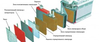
The magnetic core in the transformer is made of electrical steel plates, except for the toroidal form, in which it is made of rolled or ferromagnetic material. The coil frames are placed on insulators, and only copper wires are used. The thickness of the plates is selected depending on the frequency.
The arrangement of the windings can be made in a spiral, conical and cylindrical form. A feature of the first type is the use not of wire, but of a wide thin foil tape. Secondly, they are made with different insulation thicknesses, which affects the voltage between the primary and secondary windings. The third type is a structure with wire wound around a rod in a spiral.
Overhaul of welding transformer
Overhaul of a welding transformer is the largest type of scheduled repair, which involves:
- disassembling the unit;
- replacement of all worn components and parts.
Subject to replacement;
- coils of primary and secondary windings;
- inductor, capacitors, etc.
- all contact units: clamps, pads, etc.;
- moving units and mechanisms.
After a major overhaul, the technical parameters of the welding transformer must correspond to the new device. In many cases, by agreement with the Customer, the welder is modernized during the overhaul.
How the device works
The operating principle of IT is based on the occurrence of electromagnetic induction. So, if voltage is applied to the primary winding, then alternating current will begin to flow through it. Its appearance will lead to the emergence of a magnetic flux that is variable in magnitude. Thus, this coil is a kind of source of magnetic field. This flux is transmitted through the short-circuited core to the secondary winding, inducing an electromotive force (EMF) on it.
The magnitude of the output voltage depends on the ratio of the number of turns between the primary and secondary windings, and the maximum current depends on the cross-section of the wire used. When connecting a powerful load to the output, current consumption increases, which, with a small wire cross-section, leads to overheating of the transformer, damage to the insulation and burnout.
The operation of IT also depends on the frequency of the signal that is supplied to the primary winding. The higher this frequency is, the smaller losses will occur during energy transformation. Therefore, at a high speed of pulses supplied, the dimensions of the device can be smaller. This is achieved by operating the magnetic circuit in saturation mode, and to reduce the residual induction, a small air gap is used. This principle is used in the construction of IT, to which a signal is supplied with a duration of only a few microseconds.
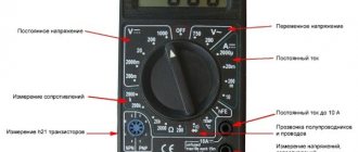
Preparation and testing
To check the operation of a pulse transformer, you can use both an analog and digital multimeter. The use of the second is preferable due to its ease of use. The essence of preparing a digital tester comes down to checking the battery and test leads. At the same time, the pointer-type device is additionally adjusted to this.
The analog device is configured by switching the operating mode to the area of measuring the minimum possible resistance. Afterwards, two wires are inserted into the tester sockets and short-circuited. Using a special construction handle, the position of the arrow is set opposite zero. If the arrow cannot be set to zero, then this indicates discharged batteries that will need to be replaced.
It's easier with a digital multimeter. Its design uses an analyzer that monitors the condition of the battery and, if its parameters deteriorate, displays a message on the tester screen indicating that it needs to be replaced.
When checking transformer parameters, two fundamentally different approaches are used. The first is to assess the serviceability directly in the circuit, and the second - autonomously from it. But it is important to understand that if the IT is not removed from the circuit, or at least a number of pins are not disconnected, then the measurement error can be very large. This is due to other radioelements that shunt the input and output of the device.
Procedure for identifying defects
An important step in checking a transformer with a multimeter is identifying the windings. However, their direction does not play a significant role. This can be done using the markings on the device. Usually a certain code is indicated on the transformer.
In some cases, a diagram of the location of the windings or even their conclusions may be marked on the IT. If the transformer is installed in the device, then a circuit diagram or specification will help in finding the pinout. Also often the designations of the windings, namely the voltage and the common terminal, are signed on the PCB itself near the connectors to which the device is connected.
Once the conclusions have been determined, you can proceed directly to testing the transformer. The list of malfunctions that may occur in the device is limited to four points:
- core damage;
- burnt out contact;
- insulation breakdown leading to an interturn or frame short circuit;
- wire break.
The verification sequence is reduced to an initial external inspection of the transformer. It is carefully checked for blackening, chips, and odor. If no obvious damage is detected, then proceed to measurement with a multimeter.
Investigation for open circuit and short circuit
To check the integrity of the windings, it is best to use a digital tester, but you can also examine them using a pointer tester. In the first case, the diode testing mode is used, indicated on the multimeter by the symbol -|>| —))). To determine a break, test leads are connected to the digital device. One is inserted into the connectors marked V/Ω, and the second is inserted into COM. The roller switch is moved to the dialing area. The measuring probes are sequentially touched to each winding, red to one of its terminals, and black to the other. If it is intact, the multimeter will beep.
An analog tester performs the test in resistance measurement mode. To do this, the tester selects the smallest resistance measurement range. This can be implemented through buttons or a switch. The probes of the device, as in the case of a digital multimeter, touch the beginning and end of the winding. If it is damaged, the arrow will remain in place and will not deviate.
The same procedure is used to check for short circuits. A short circuit may occur due to an insulation breakdown. As a result, the winding resistance will decrease, which will lead to redistribution of the magnetic flux in the device. To carry out testing, the multimeter switches to resistance testing mode. By touching the windings with probes, they look at the result on a digital display or on a scale (arrow deflection). This result should not be less than 10 ohms.
To make sure that there is no short circuit on the magnetic circuit, touch the “hardware” of the transformer with one probe, and touch the second one sequentially to each winding. There should be no deviation of the arrow or appearance of a sound signal. It is worth noting that the interturn short circuit can only be measured with a tester in an approximate form, since the error of the device is quite high.
Voltage and current measurements
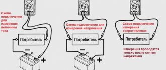
If a transformer is suspected of malfunctioning, testing can be carried out without completely disconnecting it from the circuit. This testing method is called direct, but is associated with the risk of electric shock. The essence of current measurement is to perform the following steps:
- one of the legs of the secondary winding is unsoldered from the circuit;
- the black wire is inserted into the COM socket of the multimeter, and the red wire is connected to the connector marked with the letter A;
- The device switch is moved to the position corresponding to the ACA zone.
- The probe connected to the red wire touches the free leg, and the black wire touches the place to which it was soldered.
When voltage is applied, if the transformer is operational, a current will begin to flow through it, the value of which can be seen on the tester screen. If IT has several secondary windings, then the current strength is checked on each of them.
The voltage measurement is as follows. The circuit with the transformer installed is connected to the power source, and then the tester switches to the ACV (alternating signal) region. The wire plugs are inserted into the V/Ω and COM sockets and touch the beginning and end of the winding. If the IT is normal, the result will be displayed on the screen.
Removing characteristics
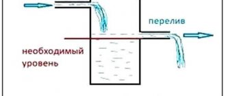
To be able to check a transformer with a multimeter using this method, its current-voltage characteristic is necessary. This graph shows the relationship between the potential difference at the terminals of the secondary windings and the current strength leading to their magnetization.
The essence of the method is as follows: the transformer is removed from the circuit, and pulses of different sizes are applied to its secondary winding using a generator. The power supplied to the coil must be sufficient to saturate the magnetic circuit. Each time the pulse changes, the current in the coil and the voltage at the output of the source are measured, and the magnetic circuit is demagnetized. To do this, after removing the voltage, the current in the winding increases in several approaches, after which it decreases to zero.
As the current-voltage characteristic is taken, its real characteristic is compared with the reference one. A decrease in its slope indicates the appearance of an interturn short circuit in the transformer. It is important to note that to plot the current-voltage characteristic it is necessary to use a multimeter with an electrodynamic head (pointer).
Thus, using a regular multimeter, you can with a high degree of probability determine the performance of IT , but for this it is best to perform a set of measurements. Although, to correctly interpret the result, you should understand the operating principle of the device and imagine what processes occur in it, but in principle, for successful measurement it is enough just to be able to switch the device to different modes.
Malfunctions of welding transformers and methods for their elimination
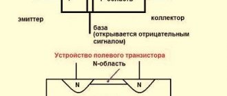
The physical principle of operation of a welding transformer is no different from a conventional step-down transformer. It is obvious from the explanatory figure “The principle of operation of a step-down transformer.” You can consider in more detail in this article the design and operating principle of a transformer welder.
Operating principle of a step-down transformer. East. https://moiinstrumenty.ru/svarochnyj/raschet-svarochnogo-transformatora.html.
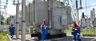
The appearance of the welder is shown in the figure “Welding transformer”.
Welding transformer. East. https://moiinstrumenty.ru/svarochnyj/svarochnyi-transformator-svoimi-rukami.html
The most common malfunctions of welding transformers and methods for eliminating them are summarized in the table.
ATTENTION! When performing any repairs, be sure to disconnect the device from the power supply.
| Description of faults | Causes of malfunctions | Elimination method |
| Spontaneous shutdown | Spontaneous shutdown of the welding machine occurs due to the activation of its electrical protection when connected to the power supply. The reason for this may be:
|
|
| Strong humming of the transformer, often accompanied by overheating | The reasons may be the following:
|
|
| Excessive heat | The reasons may be caused by violation of operating rules and regulations:
Excessive heating of the welding machine can lead to complete destruction of the electrical insulation of the windings and the need for major repairs of the entire device. Therefore, this defect must be eliminated immediately upon detection. | Elimination of the defect consists of strict compliance with the requirements of the “Welding Transformer Operating Instructions” |
| Extremely hot contacts | The cause of excessive heating of the contacts on the terminal block is most often poor electrical contact: this leads to high “transition resistance”. A large electric current flows through the contacts, which creates the release of a large amount of thermal energy. This causes the connection and the wires connected to it to become very hot. Eventually:
|
|
| Low welding current | The reason may be:
| If the voltage of the power supply does not correspond to the norm, then this should be eliminated (change the generator settings, use a powerful voltage stabilizer, etc.). If the supply voltage is normal, then you should check the welding current regulator and eliminate the malfunction. |
| Welding current too high | The reason may be:
Increased voltage of the power supply most often occurs when powered by mobile generators. In electrical networks, this parameter is regulated centrally. A sharp increase is possible only in the event of an accident (break of the “neutral wire” at the transformer substation). IMPORTANT. In the event of an increase in voltage in the electrical network, all electricity consumers at the control panel should be immediately turned off (otherwise they will fail - “burn out”). | If the output voltage of the mobile generator does not correspond to the norm, this should be eliminated by changing its settings. If the supply voltage corresponds to the standard, you should check the welding current regulator. Do not start work until the detected malfunction is eliminated. |
| Poor adjustment of welding current | The cause of this defect is malfunctions in the welding current control mechanisms. Different designs of welding transformers use different adjustment schemes. However, failures can be divided into the following groups:
| To carry out repairs, it is necessary to remove the protective casing and inspect the current control mechanism to detect a malfunction:
|
| Sudden breakage of the welding arc and inability to ignite it again | When trying to re-ignite, only small sparks are produced. The reasons may be the following:
|
|
| High current consumption from the network when there is no load | The reason for this is the short circuit of the winding turns. | If it cannot be eliminated by local restoration of the insulation, then the coils should be replaced. |
The thinnest part of the welder is the terminal block.
Terminal block.