Connecting the hydraulic tank to the water supply system
The hydraulic accumulator can be used in conjunction with both a surface and submersible pump. Each type has its own connection diagram. Having decided to use a submersible pump, you need to know about the sequence of operations that you need to do:
The check valve protects the submersible pump from the water pressure of the hydraulic tank
- A check valve is installed at the pump outlet. It is needed to protect the submersible apparatus from the water pressure of the hydraulic tank.
- The check valve is connected to a hose and the pump is installed in a well or well. This must be done correctly using a depth gauge. The pump is lowered into the water on a rope so that the distance to the surface is at least 30–40 cm.
- The hose removed from the well or borehole is connected to the fitting. It is necessary for branching water flows. The fitting has five outlets.
- Connect to the remaining 4 outlets of the fitting: hydraulic accumulator, pressure switch, monometer and pipeline.
- They install a pipeline into the home.
The connected parts of such a water supply system are sealed as much as possible. For this, it is popular to use a special fum tape.
Features of electronic automation
In relation to electronic pump control units, several important points should be noted:
- Certain devices will not allow you to regulate the pump on and off pressure, since this parameter is defined by the manufacturer as unchanged.
- Some devices are able to turn off only when the pump reaches the maximum pressure level. Sometimes this function can cause inconvenience, for example, a pressure level of 5 Bar is quite high for an ordinary dacha or country house, for which 3 Bar is quite enough to provide water supply. Accordingly, there is a need to regulate the pressure level, which will require the owner to additionally purchase a pressure reducer, which is very expensive.
Therefore, before purchasing any automation for a pump, it is very important to familiarize yourself with the parameters of the device itself, which will protect the water supply system from increased load, as well as from failures and breakdowns. Some owners, for one reason or another, do not want to install a hydraulic tank
In this case, it is advisable to find a note in the instructions for the device indicating whether it supports this function or not. Although experts advise installing a hydraulic accumulator, even if according to the instructions it is not necessary. If the automation works correctly, even a small hydraulic tank with a volume of 50 liters will reduce the number of pump starts and stops. In this case, there is no need to install devices with an anti-cycling function, since the hydraulic tank will solve the problem of a small leak in the water supply system. If installing a hydraulic accumulator is completely impossible, you should at least purchase a water hammer damper (if it is not built into the automation).
Some owners, for one reason or another, do not want to install a hydraulic tank. In this case, it is advisable to find a note in the instructions for the device indicating whether it supports this function or not. Although experts advise installing a hydraulic accumulator, even if according to the instructions it is not necessary. If the automation works correctly, even a small hydraulic tank with a volume of 50 liters will reduce the number of pump starts and stops. In this case, there is no need to install devices with an anti-cycling function, since the hydraulic tank will solve the problem of a small leak in the water supply system. If installing a hydraulic accumulator is completely impossible, you should at least purchase a water hammer damper (if it is not built into the automation).
Semi-automatic well pump control
Semi-automatic control of a well pump using STM32 in the Arduino environment
Many owners of household plots have water wells on their properties, and may have encountered the problem of silting of the well/rotting water when the well was idle from autumn to spring.
It just so happened that the well on my site stood idle for several years, and when it was used, it took very little water.
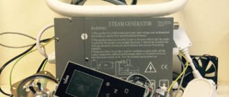
Having tried to clean it in various ways, it was understood that everything was not so bad and it was enough to ensure a stable water supply. To do this, a simple device was assembled, consisting of a power supply with a micro-USB adapter (phone charger, not pictured), a blue pill board based on stm32f103c8t6 stone, a relay module, a two-pole magnetic starter, a conventional closed-type push-button switch, and assembled in a junction box. I prepared the microcontroller board according to HWman's manual. In the comments there was a request to clarify that the STM32 can be flashed with a special bootloader, which subsequently allows you to program it via USB, like regular Arduinos.
I program using a plugin in Visual Studio Community. Installing the plugin is simple and does not require any mental effort. I will only add that the plugin requires ARDUINO IDE installed. Professionals, I believe, will be confused by this approach, but the finished product works stably for more than six months and fulfills the task. Still, I'm open to ideas to improve the device.
We get an extremely convenient environment with code parsing, IntelliSense, and what is subjectively important - a dark theme. Because little eyes.
We sew the scarf:
Code
/* Name: Nasos.ino Created: 02.23.2017 19:08:20 Author: Ksiw The architecture of the program consists of setting a flag to turn on the relay in various ways, in order to subsequently check its (flag) status and then switch the relay to corresponding position. If the manual start button is not pressed, the cycle is performed approximately 10 times per second. If the button is pressed, then a tenth of a second is first given to avoid chatter, then the button status is checked 20 times/sec. 99% of the time the stone rests while in delay() */ unsigned long Work = 2UL*60; /*2 minutes of work*/ // indicate here the work time in minutes, with type casting // this is not just some kind of nonsense... However! Without reduction, multiplication was calculated incorrectly. const unsigned long Sleep = (unsigned long)20*60; //and then there is idle time unsigned long TimeLeft; //seconds left before switching int tempo = iter; //immediately print int iter = 10; //skip iterations before the next output to the port unsigned long timeNextSwich; int button = PB4; //button pin unsigned long WorkTime, SleepTime ; // time in milliseconds duration of pump activation in minutes bool handOn = false; //manual enable flag bool flag; //relay status flag int RelayPin = PB7; //relay control pin unsigned long PreviousMillis = 0; unsigned long CurrentMillis = millis(); unsigned long fullTimeIteration = 4200000000; //calculating the program restart time //(long 4,294,967,295) //———————prototypes void SwitchFlag(); void SwitchRelay(); void Button(); unsigned long SecToMillis(unsigned long); void ResidueTime(); void ResetTimeToWork(); //————————————-to the beginning of the program————————— void(*resetFunc) (void) = 0; //********************************START*************** ************************* void setup() { Serial.begin(115200); flag = false; //turning on the relay when loading the microcontroller //————Initializing the relay output pinMode(RelayPin, OUTPUT); pinMode(button, INPUT); digitalWrite(RelayPin, flag); Serial.println(""); WorkTime = SecToMillis(Work); SleepTime = SecToMillis(Sleep); PreviousMillis = millis(); } void loop() //****************************LOOP************** ******************************** { while(true) { CurrentMillis = millis(); //current time ResetTimeToWork(); //overflow check milis() SwichFlag(); //checking the need to switch SwitchRelay(); //switched the relay if the flag changed ResidueTime(); //output to port Button(); //processing the button tempo++; handOn = false; delay(100); } } //————————————-flag switching———————————————- void SwitchFlag() { if(flag && CurrentMillis-PreviousMillis>=SleepTime ) { PreviousMillis = CurrentMillis; flag = false; //if the difference between the previous measurement and the current time is greater than sleep time, but set the flag to turn on Serial.println("Flag On"); } else if(!flag && CurrentMillis-PreviousMillis>=WorkTime) //Else, if the relay is on and it’s time to turn off, switch the flag to “off” { PreviousMillis = CurrentMillis; flag = true; Serial.println("Flag OFF"); } } //————————————-button operation——————————————————- void Button() { if(digitalRead(button)= =HIGH) //if the button is pressed { do { if(handOn) { delay(50); continue; } Serial.println("TURNED ON"); digitalWrite(RelayPin, LOW); //then turn on the relay flag = true; handOn = true; delay(100); //and hold down a little }while (digitalRead(button)==HIGH); CurrentMillis = millis(); //find out and record when it ended PreviousMillis = CurrentMillis; //update the time of the last actions delay(20); } } //————————————-converting seconds to milliseconds————————— unsigned long SecToMillis(unsigned long Temp) { return Temp*1000; } //————————————-time before switching———————————————- void ResidueTime() { if(CurrentMillis iter) { if(flag) { TimeLeft = timeNextSwich/1000+1; Serial.print(" Time to ON: "); Serial.print(TimeLeft); Serial.print("sec"); Serial.println(""); } else { TimeLeft = timeNextSwich/1000+1; Serial.print(" Time to OFF: "); Serial.print(TimeLeft); Serial.print("sec"); Serial.println(""); } tempo = 0; } if(tempo > iter) //output every new iteration { if(flag) { TimeLeft = (PreviousMillis+SleepTime-CurrentMillis)/1000+1; Serial.print(" Time to ON: "); Serial.print(TimeLeft); Serial.print("sec"); Serial.println(""); } else { TimeLeft = (PreviousMillis+WorkTime-CurrentMillis)/1000+1; Serial.print(" Time to OFF: "); Serial.print(TimeLeft); Serial.print("sec"); Serial.println(""); } tempo = 0; } } //————————————-transition function during overflow milis(); void ResetTimeToWork() { while(CurrentMillis=CurrentMillis) //while the next switching time is greater than the current one { CurrentMillis = millis(); ResidueTime(); Button(); // if the button is pressed, the time of the last action is overwritten and we exit the ResetTimeToWork() function! if(CurrentMillis>PreviousMillis) return; tempo++; //for correct operation ResidueTime(); } flag = false; PreviousMillis = CurrentMillis; //update the change time CurrentMillis = millis(); return; } if(!flag) { timeNextSwich = WorkTime-(4294967295-PreviousMillis); while(timeNextSwich>=CurrentMillis) //while the time of the next switch is greater than the current one { CurrentMillis = millis(); ResidueTime(); Button(); if(CurrentMillis>PreviousMillis) return; tempo++; } flag = true; PreviousMillis = CurrentMillis; CurrentMillis = millis(); return; } } } //—————————————relay switching—————————————————— void SwitchRelay() { if(!flag) { digitalWrite( RelayPin, flag); // turn on the relay } else { digitalWrite(RelayPin, flag); // turn off the relay } } Regarding the code. The program was written in several approaches, modified as shortcomings were identified. Looks quite confusing, but I'll try to clarify.
It works like this:
0)
The architecture of the program is designed to poll any external device (button, pressure sensor, timer, etc.) and set a flag to turn the relay on or off, and then use a separate function to check the state of the flag and switch it to the appropriate position.
1)
The program code relies on the millis() function timer, the ResidueTime() function calculates the next relay switching time, SwichRelay() checks the status of the flag and issues a switching command if necessary.
2)
The relay turns on when a low level signal is supplied from the PB7 leg. When the device is turned on, after initializing the MK, the relay switches to the ON position, supplying voltage to the starter coil, which in turn supplies voltage to the pump.
3)
The device operates for 2 minutes, after which it goes into standby mode for 20 minutes.
4)
Turning on the switch is processed immediately, and after turning off the program maintains a downtime interval of 20 minutes. This is done so that the well replenishes the pumped out water and prevents the pump from running dry.
5)
The code also contains the ResetTimeToWork() function, which is triggered when the millis() function overflows, which
Returns the number of milliseconds since the start of execution of the current program on the Arduino board.
This amount is reset to zero due to overflow after approximately 50 days. (from Arduino.ru website)
Consequently, to prevent the device from “falling” after this period of continuous operation, the mentioned function has been developed to ensure stable operation of the device without an additional restart.
Let's start assembling the circuit.
Assembly diagram:
The signal from the PB4 leg must be pressed to ground with a 4.7KΩ resistor, otherwise the relay will not work correctly.
In the box we install a dinray for the starter:
And we install the remaining spare parts, securing their position with hot snot, as in the first photo.
It is necessary to cut a hole in the lid for the starter; it is higher than the depth of the box.
Don’t forget to install the power supply for the board, you can hide it inside the box, there is still enough space in it, or take it outside and plug it into the nearest outlet.
The device is ready, all that remains is to connect the 230V cable to the starter terminals and connect the load.
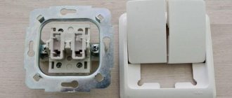
The switch used was the old one that turned on the pump. The outside has irremovable cement stains and other abrasions, but it has a sealed body, the inside is completely intact and will work properly in the garden for a long time. Considering the scanty switching current - almost forever, until it breaks mechanically.
Thanks to HWman for the article on making stm32 work in the ARDUINO framework.
I am attaching the archive with the sketch.
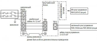
Connection diagram
Depending on the type of pump, the connection diagram may vary.
Installation and connection of a submersible pump and automation
For each generation of automation, the connection diagram to the pumping system has its own differences; often its features are described in the operating instructions.
Let's consider the connection diagram using the example of equipping a submersible pump with 1st generation automation with a hydraulic accumulator.
- First, the hydraulic accumulator is connected. According to the diagram, the nodes are connected in series. Fum tape is used to seal threaded connections.
- The first one to fit on the thread is the “American” one, with its help during operation the hydraulic accumulator will be serviced in order to replace the membrane.
- On the second side, a bronze adapter with threaded branches is screwed to the “American” one.
- Two units are screwed to them: a pressure gauge and a pressure switch.
- Next, a PVC pipe is installed using a fitting adapter on the end of the bronze adapter of the accumulator.
- On the other hand, the pipe is attached to the pump using a fitting.
- The supply pipe and pump are laid on a level area.
- A safety cable with a spare length of 3 meters is attached to the loops of its body.
- The cable and cable are attached to the pipe at intervals of 1.5 meters with clamps. The second end of the safety rope is secured next to the casing.
- After which the pump is lowered into the well, and the safety rope is tightened.
- Next, the casing pipe is covered with a protective cap, which protects the well from clogging.
- The cable is connected to the relay and led to the control electrical cabinet.
- Immediately after connection, water is pumped into the accumulator. At this moment, it is necessary to bleed the air by opening the tap.
- After water flows without air, the tap is closed and the pressure gauge readings are checked. Standardly, the relay has settings for the upper pressure limit - 2.8 atm, and for the lower limit - 1.5.
Installation and connection of a surface pump with automation
With this type of pump, the automation connection has a number of differences, although the sequence of its connection is the same as for the submersible type. The differences are as follows:
- a PVC pipe is connected to the pump inlet for drawing water from diameters from 25 to 35 mm;
- a check valve is attached to the second end by means of a fitting and lowered into the well, while the pipe must have a length sufficient for its end to be submerged in water by about a meter, otherwise air will be trapped;
- before starting operation, the engine is filled with water through the filler hole and the intake pipe;
- If all components are properly sealed, turning on the pump will be accompanied by pumping water.
Pumping station valve control diagram
Let's consider the circuit of a pump valve, which is controlled through a gearbox by a small-sized asynchronous electric motor. When voltage is applied to the circuit, the green lamp begins to glow fully. It signals the closed position of the plug. The pumping unit is started by the RU level relay. One of the RU contacts gives a command to start the electric motor M1 of the pump unit, and the second closes the circuit of the relay coil RP1, which controls the operation of the plug motor M2.
After starting the pump and increasing the pressure in the water supply system to a normal level, the contact of the pressure switch RD, connected in series with the contact RU in the RP1 coil circuit, closes. Relay RP1 is pulled up, closes the normally open contact and supplies voltage to the contactor for opening the KO valve. The contactor starts the M2 electric motor to open the valve. The process of opening the valve is controlled by the limit switch VK2, as well as by a brightly burning red lamp. After the valve is completely opened, the contacts BK2 will open, the KO will turn off, and the valve control motor will stop. The red lamp will burn at full intensity, and the green lamp will go out completely. The valve closing circuit works in a similar way. For emergency shutdown of the control circuit, the VKA emergency switch is used. When the switch is triggered, both warning lamps go out.
Purpose of automation for a well
The control unit controls the cycles of turning the pump on and off, protects against overheating and water hammer
Automatic control devices for submersible pumps are used to control their operation and protect against unusual situations. Electronic or mechanical devices maintain the pressure parameters set by the consumer in the water supply network. In the event of emergency situations such as power surges or lack of water, automation prevents breakdown of an expensive unit.
Main components of the control unit:
- Pressure switch - ensures that the pump is turned on and off in accordance with the setting of the minimum and maximum pressure threshold in the water supply system. The controller can be equipped with a pressure gauge and a “dry running” sensor.
- Float switch - installed on the pump, used to control the liquid level.
- A hydraulic accumulator is a sealed metal container with an elastic membrane inside into which water is pumped. Part of the tank is filled with air under pressure. The device is necessary to maintain stable pressure.
- Press control or flow switch - the device has a check valve that is used to turn on the pump when the pressure drops. The device turns off the unit when there is no liquid (“dry running”). Used in a system without a hydraulic accumulator.
Automatic water pump control
This device can be useful in the country or on the farm, as well as in many other cases where control and maintenance of a certain water level in the tank is required.
So, when using a submersible pump to pump water from a well for irrigation, you must ensure that the water level does not drop below the position of the pump. Otherwise, the pump, operating at idle speed (without water), will overheat and fail.
A universal automatic device circuit will help you get rid of all these problems. It is simple and reliable, and also provides the possibility of multifunctional use (water lifting or drainage).
The circuit circuits are in no way connected to the tank body, which eliminates electrochemical corrosion of the tank surface, as is the case in many previously published circuits for similar purposes.
The principle of operation of the circuit is based on the use of the electrical conductivity of water, which, falling between the sensor plates, closes the base current circuit of transistor VT1. In this case, relay K1 is activated and with its contacts K1.1 turns the pump on or off (depending on position 82).
Plates made of any metals that are not susceptible to corrosion in water can be used as sensors F1, F2. For example, you can use a used stainless razor. The distance between the sensor plates can be 5...20 mm, and they are mounted on dielectric bases made of materials that do not retain water, for example, plexiglass or fluoroplastic.
When you turn on the power to the circuit with toggle switch S1, if there is no water in the tank, relay K1 will not work and its contacts K1.1 (normally closed) will provide power to the pump until the water reaches the level of sensor F1. At the same time, the relay will operate and turn off the pump with its contacts. The pump will turn on again only when the water level drops below the level of sensor F2 (contacts K1.2 connect it to operation when the relay is activated). This is how the circuit works in the WATER RAISING mode (the initial position of toggle switch S2 is indicated in the diagram just for this mode). When switching toggle switch S2 to the DRAINAGE position, the circuit can be used to automatically control a submersible pump when pumping out water - turn it off when the water level drops below the position of sensor F2. In this case, the water intake of the pump should be located slightly below the sensor itself.
The circuit is not critical to the parts used. Any transformer is suitable, with a voltage in the secondary winding of 24...30 V - it is related to the operating voltage of the relay winding. The circuit uses: relay K1 type TKE52POD; capacitor C1 type K50-29 or similar. The LED can be anything, the KT827 transistor can be used with the letter A, B, C or KT829A, B, V.
It is more convenient to connect sensors F1, F2 to the circuit via a connector (it is not shown in the figure).
If assembled correctly, the circuit does not require adjustment.
List of radioelements
| Designation | Type | Denomination | Quantity | Note | Shop | My notepad |
| VT1 | Bipolar transistor | KT827V | 1 | Search in the Otron store | To notepad | |
| VD1-VD5 | Diode | KD212A | 5 | Search in the Otron store | To notepad | |
| C1 | Electrolytic capacitor | 1000 µF 63 V | 1 | Search in the Otron store | To notepad | |
| R1 | Resistor | 3 kOhm | 1 | 1 W | Search in the Otron store | To notepad |
| R2 | Resistor | 100 kOhm | 1 | Search in the Otron store | To notepad | |
| FU1 | Fuse | 3 A | 1 | Search in the Otron store | To notepad | |
| K1 | Relay | 1 | Search in the Otron store | To notepad | ||
| HL1 | Light-emitting diode | AL307B | 1 | Search in the Otron store | To notepad | |
| T1 | Transformer | 1 | Search in the Otron store | To notepad | ||
| S1 | Switch | 1 | Search in the Otron store | To notepad | ||
| Electric motor | 1 | Search in the Otron store | To notepad | |||
| XP1 | Power plug | 1 | Search in the Otron store | To notepad | ||
| X1, X2 | Connector | 2 | Search in the Otron store | To notepad | ||
| F1, F2 | Electrode | 2 | Search in the Otron store | To notepad | ||
| Add all | ||||||
Role in the water supply network
It would seem that the device simply passes water through itself. Could you do without it? In fact, it is with the help of a hydraulic tank that stable pressure is maintained in the water supply system.
The water pump, if present, does not turn on so often, which allows you to use its operational resource economically. In addition, the water extraction and transportation system is reliably protected from water hammer.
If for any reason the voltage in the electrical network is lost, a small “emergency” supply of water in the tank will help solve priority economic problems.
Let us clarify the list of advantages that this fairly simple device provides:
- Premature pump wear. There is a certain supply of water in the membrane tank. It satisfies the primary needs of cottage owners. And only when the supply runs out will the pump turn on. It should be noted that all pumps have a turn-on rate of an hour. If there is a hydraulic accumulator, this figure will not be exceeded, and the unit will last longer.
- Stabilization of pressure in the system. If you turn on two taps at the same time, for example in the bathroom and in the kitchen, pressure changes can affect the water temperature. This is very unpleasant, especially for those household members who are taking a shower at this moment. Thanks to the hydraulic accumulator, such misunderstandings can be avoided.
- Water hammer. These phenomena, which can damage the pipeline, can occur when the pump is turned on. With a hydraulic tank, the risk of water hammer is virtually eliminated.
- Water supply. In a country house, the problem of water supply is especially acute. If there is a sudden power outage and the pump cannot perform its functions, then it is no longer necessary to store a supply of water in a bucket or other container to solve urgent problems. It is available in the hydraulic accumulator tank and is regularly updated.
Obviously, the presence of this device in a water supply system independent of centralized networks is not accidental. It is necessary and useful.
The hydraulic accumulator in the water supply circuit performs a number of significant functions: it protects equipment from water hammer, provides a supply of water, and creates conditions for automating its intake.
Types of pumps used
Water supply stations are equipped with several types of pumping equipment:
- Standard surface mounted models. Allows you to supply water from a depth of up to 8-9m.
- Surface, with internal ejector. The internal ejector system allows you to increase the pressure in the system and the suction depth to 10-12m.
- With external ejector. The ejector is lowered to the base of the suction pipe, which increases the water suction depth to 30m. The disadvantage of ejector models is their noise. Therefore, when purchasing such devices, prepare in advance for some discomfort, or take care of soundproofing the room.
- Submersible pumps. The use of submersible types of pumping equipment is advisable for wells with a depth of over 30 m. Such pumps are lowered directly into the well, suspended on cables half a meter from its bottom.
Electronic pump control units
Electronic automation units for pumps have numerous advantages over devices from the first category and consist of the following elements and functions:
- Pressure meter. It is he who gives the pump the commands “Friend, it’s time to turn on” and “Friend, it’s time to turn off.”
- Flow switch. If there is no flow (the water supply has run out or the tap is closed), the flow switch will recognize this and send a signal to the automation system, which will turn off the pump.
- Dry running protection. It operates on the basis of a pressure sensor and a flow switch.
- Status indicators. They signal certain operating modes of the automation, for example, emergency mode.
- Automatic pump restart function. This is carried out if the dry-running protection has tripped.
- Check valve. A system with a built-in check valve keeps pressure behind itself, so it may not be suitable in all cases. So, if you plan to install water supply between the water supply source and the automation system, then the check valve system will not allow this to be done. Therefore, if water analysis between the source and automation is required, then you need to install conventional automation (from the first category).
- Built-in hydraulic shock absorber. Its indispensability lies in the fact that it will protect the entire water supply system from breakdown due to sudden pressure surges.
- Built-in pressure gauge. Or light / digital indication of pressure in the system. That is, there is no need to purchase it additionally, as is the case with devices from the first category.
- Smooth start. Certain devices in this category are capable of smoothly starting the pump, which significantly increases its service life.
- Anti-cyclicality. The anti-cycling function is indispensable if there is no hydraulic accumulator and there is a slight leak in the water supply system (for example, the toilet valve does not fit tightly). In this case, the pump will be forced to turn on and off uninterruptedly, which will ultimately lead to the breakdown of any component. Anti-cycling will detect a leak and turn off the pump.
As you can see, automation devices from the second category have significant advantages that guarantee long and stable operation of the water supply pumping station.
Pump control circuit diagram
When the Eurocube is empty, all sensors are not in contact with water. The inputs of logic element D1.3 receive a high-level voltage through resistor R4 from the power source. In this case, the output D1.3 will be logical zero. It goes to pin 5 of element D1.2, which, together with element D1.1, forms a regular RS trigger with inverse inputs.
Since pin 6 of D1.2 is zero, the trigger is set to a state where output D1.1 is also zero, and a logical one appears at the output of element D1.4. The current from output D1.4 through resistor R6 enters the base of transistor VT1, it opens and relay K1, the winding of which is connected in its collector circuit, connects the pump with its contacts, through connector X2 and X2, to the power supply.
Fig.1. Schematic diagram of an automatic water pump control device.
The pump begins to pump water into the Eurocube. Sensors E2 and E3 are immersed first. A logical zero is set at the inputs of element D1.3, and a unit at its output. But the RS trigger on D1.1 and D1.2 does not change its state. As soon as the water level reaches sensor E1, pin 1 of D1.1 is set to logical zero.
The RS trigger switches and now output D1.4 is zero. Transistor VT1 closes and relay K1 turns off the pump. Eurocube is full.
Subsequently, water from the “Eurocube” is consumed for various needs, and its level in it decreases below the E1 sensor. The voltage at pin 1 of D1.1 rises to a logical one, but this does not affect the state of the RS trigger in any way. The pump will be turned on only when the E3 sensor “dries out”.
Principle of operation and varieties
When using a water supply, the liquid level in the source, flow rate and pressure change. In addition, the water may simply disappear. The automatic system responds to all these parameters.
Manufacturers can install some automatic elements on submersible pumps; they need to be supplemented with separate units and a hydraulic accumulator. Advanced models are equipped with a modular unit that combines all devices.
Surface devices such as pumping stations have a modular configuration. All elements are configured and installed on a common frame. This is a convenient option - you don’t have to build a chain of automatic control devices.
Device and principle of operation
Most wells serving summer cottages and residential country houses have a water supply depth of no more than 20 m. This depth is ideal for using automatic pumping stations.
This device represents a set of equipment designed to fulfill two main purposes:
- Supplying water from a water supply source to the intra-house network.
- Maintaining the pressure in the plumbing system necessary for the uninterrupted functioning of plumbing fixtures and household appliances.
If there is no water in the house, the functioning of such amenities of civilization as showers, washing machines, kitchen faucets, and sewerage systems is impossible. Therefore, a pumping station for a private house acts as the basis for its improvement.
On the modern domestic market you can find a significant number of different automatic water supply devices designed for installation in a private home. But, despite some design differences, all these models have the same principle of operation and a similar design.
Main functional units of water pumping stations:
- A suction pump for lifting water from a well and supplying it under a certain pressure into the internal pipeline system. Most often, a surface pump is used here. But, if you need to pump water from a deep artesian well, deep submersible pumps are used as part of the stations.
- Damper storage tank or hydraulic accumulator. This device is intended to create a certain water reserve just in case of emergency. For example, if a pump breaks down or there is a power outage, the hydraulic accumulator will be able to maintain pressure for some time, allowing residents to use basic plumbing fixtures.
- Pressure sensors (pressure gauges) connected to a relay, and those, in turn, to a pump electric motor. If the motor overheats, or there is an emergency disappearance of water in the supply system, the control equipment must independently stop the pump to avoid its breakdown.
- Pumping station control unit. Here are the on/off buttons, as well as devices for adjusting the operation of the station. With their help, you can set the highest and lowest pressure values at which the device will automatically turn on or off.
- Check valve. It is installed on the water intake pipeline and prevents water from rolling back into the supply well.
Correctly setting up a new device
The new hydraulic tank should be checked to see what its internal pressure level is. It is assumed that it should be 1.5 atm. But during transportation of the product from the place of production to the warehouse and during storage, a leak could occur, which reduced this important indicator at the time of sale. You can check the pressure by removing the cap on the spool and taking measurements.
To measure pressure, you can use different types of pressure gauges:
- Electronic. These are expensive devices. Their performance may be affected by temperature and battery charge.
- Mechanical. They are produced in a metal case, otherwise called automobile ones. If this device has successfully passed the test, then you couldn’t find it better. To get the most accurate value, since you will only need to measure 1-2 atm, it is better to buy a device with a large number of divisions on the measuring scale.
Inexpensive pumping stations and automatic pumps are most often equipped with pressure gauges in a plastic case. The error in the readings of such Chinese models is too great.
If there is less air in the tank than needed, water will take its place. This will affect the water pressure in the water supply. At high pressure, the pressure will always be high. Higher pressure will provide less water in the membrane bulb, so the pump will have to turn on more often. If there is no light, the water supply may not be enough for all needs.
That's why sometimes it makes more sense to sacrifice pressure to achieve other important goals. However, it is better not to reduce the pressure below the recommended values, nor to exceed the maximum characteristics. Lack of pressure can lead to contact of the bulb surface with the tank body, which is undesirable.
You can use different devices to measure pressure, but the optimal one is a relatively inexpensive automobile pressure gauge with a metal body and a fairly comprehensive scale of measurement results.
Setting up the hydraulic accumulator when connecting
Before using a water supply system with a hydraulic accumulator in a private house, you need to know what the pressure in the hydraulic accumulator should be for its optimal operation; take a portable pressure gauge to take readings. A typical water line with a standard pressure switch has response thresholds from 1.4 to 2.8 bar, the factory setting of the pressure in the hydraulic tank is 1.5 bar. To ensure that the hydraulic accumulator operates efficiently and is completely filled, the lower threshold for switching on the electric pump is selected at 0.2 bar for a given factory setting. more - a threshold of 1.7 bar is set on the relay.
If during operation or due to a long storage period it is determined that the pressure in the hydraulic tank is insufficient when measured with a pressure gauge, proceed as follows:
- Disconnect the electric pump from the power supply.
- Remove the protective cover and press the hydraulic tank valve in the form of a nipple head at the outlet of the device - if liquid comes from there, then the rubber membrane has been damaged and needs to be replaced. If air comes from the hydraulic tank, its pressure is measured using a car pressure gauge.
- Drain the water from the main by opening the tap closest to the expansion tank.
- Using a hand pump or compressor, pump air into the battery tank until the pressure gauge reads 1.5 bar. If, after automation, the water rises to a certain height (high-rise buildings), the total pressure and operating range of the system are increased based on the fact that 1 bar. equated to 10 meters of vertical water column.
Rules for making hives
So, how do you make a bee hive that is most comfortable for your bee colony? Housing for these hardworking, but rather whimsical insects must meet certain requirements.
- The hive must reliably protect the bee family from sudden temperature changes, precipitation, and at the same time be well ventilated.
- It should have room for ceiling and side insulation, which reduces heat loss in autumn and winter, and in summer, on the contrary, protects the bee colony from overheating.
- The entrances should be arranged so that, depending on the air temperature and the size of the family, their number can be increased or decreased.
- The hive should be made spacious so that the bees can freely place brood or food supplies. The design of a good hive allows it to easily increase or decrease in volume.
In addition, the beekeeper, before making a hive for bees, needs to make sure that it is convenient for him. To do this, all structural elements must be interchangeable and match the rest of the apiary hives. This will greatly facilitate the installation of second stores, buildings, relocation of families, and cleaning of river bottoms.
It is especially important to follow this rule when constructing frames
When deciding how to make bee hives, remember that they should be light, durable, simple and cheap to make. If their transportation to wild honey plants or crops in need of pollination is required, increased demands are placed on the strength of the hives. In addition, such hives must have good ventilation and devices for fastening individual parts (bottom, body, lid).
Pump control systems - types, purpose and scope of application
The principle of its operation is as follows. A frequency converter (FC), also called a microprocessor pump control controller, controls the on/off of pumping units based on input signals from the pressure sensor and the value specified from the keyboard. At the same time, it simultaneously adjusts the rotation speed of one of the units in order to achieve the set pressure level.
If the value differs from the set value, the PID controller calculates the difference and, depending on the situation, reduces or increases the rotation speed. When maximum speed is reached and maintained for a specified time, the microprocessor controller sends a signal to turn on the next additional (standby) unit.
The opposite actions also occur - in the case when the inverter-controlled pump reaches the minimum speed, the pump that has been running longer than the others is switched off. As a result of such processes (switching on/off taking into account the temporary output of the engine), the driving mechanism is periodically replaced.
The panels can control a group of pumps consisting of six copies, the power of each can reach up to 1 MW. They help distribute the working time of each machine evenly.
On the front panel of the cabinet there are such working parts as:
- button that resets the alarm;
- operating mode switch;
- power switch handle, warning (emergency) alarm indicator;
- electric motor operation indicator.
The design (composition) of the control cabinet has a metal frame, powder coating with a degree of protection of at least IP54. Cable entry is carried out through cable glands. Inside the standard product you will find: an external control panel, emergency control, buttons, system switches, dry-running protection, a fluid pressure meter, light bulbs, switches that protect the engine. Also included: two load control modes - automatic and manual, a thermal relay.
The available options are: frequency regulation, manual, remote control, automatic switching on of backup power, control using special programs, issuing information separately for each mechanism. Using a thermostat, fan and heater, you can stabilize the temperature inside the cabinet at any time of the year.
Interesting fact. Not everyone probably knows that you can purchase not only ready-made shields, but there is also the option of making a custom shield in accordance with your requirements and desires. However, be sure to take into account: type of control, environmental conditions, engine start mode (direct, combined, smooth), number and parameters of electric motors.
By installing a control cabinet for downhole pumping equipment, the owner will gain peace of mind, since control of the further operation of the pumps will be provided on the basis of electronic “stuffing”. Important parameters will be monitored: temperature, water level, pressure. In addition to regulating the frequency converter, the device's electric motor will start safely and smoothly. When using a cabinet to control a group of pumps, as we see, the range of functionality expands.
Adviсe
In the process of selecting, installing and operating automation for a pump with your own hands, there are nuances, knowledge of which can improve the efficiency of the circulation and drainage pump system.
Setting too high a pressure in the system negatively affects the operation of the pump, and in addition, leads to a disproportionate waste of electricity. Sometimes it just doesn't work.
The 3rd generation water pump automation uses frequency control of the pump speed; if the existing pump does not support such technology, there is no point in installing the 3rd generation automation.
You can find out more about how to connect a pressure switch to a pumping station.
General information
Special devices consist of jet relays, a sensor that controls pressure, water volume, electrode-type relays, sensors inside the tank, a pressure gauge, a float as a level sensor. Varieties of control methods for units
To control the operation of a submersible pump, special devices are used. They consist of the following elements:
1.control panel.
2.automatic control for adjusting the required pressure in the network.
3.press control.
The control panel is a unit that protects equipment during strong voltage surges and from short circuits. It is necessary to connect the unit to the liquid level and relays responsible for pressure. Sometimes the float sensor is also tied to the control panel. This unit is inexpensive, but it may not ensure efficient operation of the pump without a protective device against operation in dry mode, without a pressure control relay.
Attention! When installing it yourself, it is recommended to use a unit that has a built-in system.
The control unit, which includes press control, contains dry-running protection and automatic operation of the equipment. To control the functioning of the system, you should monitor certain parameters: water pressure, flow force. When water consumption exceeds 50 liters per minute, the pump with press control can operate without interruption. The automatic system turns off the unit if necessary, for example, when the water flow decreases and when the pressure in the network increases. When the water flow rate is less than 50 liters per minute and the pressure drops to one and a half bar, the pump starts working. If pressure surges are observed in the system, if it is necessary to reduce the frequency of equipment startup and stops when working with minimal water consumption, then the presence of automation is very important. With constantly high pressure in the network, electricity consumption will increase, while the efficiency of the equipment will decrease.
Attention! An automatic control circuit that controls the pressure indicator at one level is used when the presence of any pressure surges is very undesirable.
Methods for automating water wells
The simplest and most inexpensive way to automate wells is to install them on a mechanical pressure regulator. If the pressure created by the water is too low, the contacts of the pumping equipment are closed, and then it is turned on. After turning off the water supply, the tap must be closed and the pressure level increased.
The installation of a pressure switch equipped with a pressure gauge is carried out at any point in the pumping system, the disadvantage of which is the lack of protection against “dry running”. The pressure switch supplies electricity to the equipment if the pressure begins to drop. The pump will continue to operate until the entire system fails. Its operation must be regulated, so a hydraulic accumulator is built into the system, performing the following functions:
- preventing frequent pump starts;
- absorbing water shocks that occur in the event of a sudden closure of the tap.
A hydraulic accumulator is a tank made from ferrous metal or stainless steel. The device can be painted blue. The capacity of the device is 5-500 l. The number of starts of the pumping system depends on the volume of the tank.
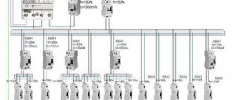
Installing an automation unit for a well is another way to control the operation of the pump. These systems are advanced, so their cost is 10-15 times higher than the price of a simple relay. The automation system must include the following elements:
- LCD display;
- dry running protection;
- pump jam protection;
- automatic start;
- hydraulic accumulator
The most expensive type of automation for well pumps is considered a frequency converter. It provides the frequency required to maintain pressure in the pumping system. It becomes operational only after opening the 2nd tap and increasing the water flow.
When using frequency converters, the minimum motor speed is used. It is 20-30% of the nominal value, which is indicated in the technical documentation for the device. If the requirement is not met, the device may fail.
Electrician in the house
Author: admin, July 21, 2013
Sensors
In one of the previous articles, a pump control circuit using reed switches was discussed. In the same article, we will consider a circuit for maintaining the required water level on a transistor and using metal rods or plates as sensors. The scheme is somewhat simpler than the previous one, but performs the same functions.
Automatic water pump control circuit
Pump control
The diagram shows:
- FU1 - 5A fuse.
- S1 - switch.
- S2 - toggle switch T3-1 (T2-1).
- M - water pump.
- T1 is a step-down transformer.
- D1-D4 - diode bridge KTs405.
- C1 - capacitor K 50-29, 1000 µF, 63 V.
- R1 - resistor MLT-0.5, 3 kOhm.
- R2 - resistor MLT-0.5, 100 kOhm.
- L1 - LED AL 307.
- D5 - diode D302.
- VT1 - Transistor KT827V.
- K1 - relay TKE52PODG(B).
- XT1, XT2, XT3 - connectors for connecting sensors.
Circuit operation
The pump control circuit is universal; it is suitable for both pumping water and filling the tank. The pumping-filling operating modes are switched using toggle switch S2. The diagram shows the position of contacts S2 for the filling mode. If you only need one operating mode, then toggle switch S2 can be eliminated.
Water level sensors D1-D3 (see first figure) are connected to the corresponding sockets XT1-XT3, while sensor D3 should be located no higher than sensor D2; if you have a metal tank, then you can connect the wire from the socket XT3 directly to the tank, for example through the bolt (pre-clean the contact point), in this case the D3 sensor is not needed, the reservoir will act as it.
In the absence of water (or when the water level is below sensor D1) in the tank and closed contacts S1, transistor VT1 is closed and the relay is de-energized, while pump M1 is connected to the network through the normally closed contacts of relay K1.1 and the contacts of toggle switch S2. The reservoir is filled with water.
When water reaches the lower level sensor D2, nothing happens, since the sensor is disconnected from the circuit by the normally open contacts of relay K1.2. When water reaches the upper level sensor D1, a base current begins to flow through the transistor, the transistor opens, relay K1 turns on and its contacts K1.1 turns off the pump. At the same time, the contacts of relay K1.2 are also closed, connecting the low level sensor D2 to the circuit. Now the pump will not turn on until the water level drops below sensor D2.
To operate the pump in water pumping mode (can also be used to protect the well pump from “dry running”), toggle switch S2 is switched to another position and now the pump will turn off when the water level drops below sensor D2 and turn on when water reaches the level of sensor D1. The pump should be lowered just below sensor D2.
You can adjust the sensitivity of the circuit by selecting the value of resistor R2.
The LED serves to indicate the supply of power to the circuit; you can replace the R1, L1 chain with a light bulb or completely exclude it from the circuit.
The transformer reduces the alternating voltage of 220 V to 24-30 V, the diode bridge D1-D4 rectifies this voltage, and capacitor C1 serves to smooth out the ripples of the rectified voltage.
Diode D5 serves to protect transistor VT1 from voltage surges when switching relay K1.
Circuit details
In principle, any transformer can be used; for the specified relay it is needed with a secondary winding voltage of 27V ± 3V.
You can use any other relay, but you must remember that the operating current of the relay contacts must be no less than the current of the pump used. For the specified TKE52PODG relay, the maximum current switched by the contacts is 5A, i.e. you can connect a maximum pump through its contacts: P=220*5=1100 W. If the relay is not powerful enough, then you can use a magnetic starter, the coil of which is connected instead of pump M, and the pump is connected through the contacts of the starter.
Instead of the KTs405 bridge, you can use diodes KD212, D302, D243-D247 or similar with a maximum rectified current of at least 1A. The same diodes can be used instead of diode D5.
Capacitor C1 can be any electrolytic with a capacity of at least 500 μF.
Resistors R1, R2 - of any type with a dissipation power of at least 0.5 W, with ratings close to those indicated. The brightness of LED L1, which can be anything, depends on the value of resistor R1.
The KT827V transistor can be replaced with KT827A (B), KT829A (B, C).
Sensors can be in the form of rods or plates made of stainless metals. The distance between sensors should not exceed 30 cm.
Write all questions and wishes in the comments below.
It will be interesting to read:
Voltage multiplier
Laying open wiring in the house
Battery charger
Headings: Useful devices, Electronic devices Tags: do it yourself, electronics
Connection diagram for pressure switch RD5 and protection LP/3
Replacing the automatic unit with a protective relay LP/3 allows you to reduce the cost of installing your own water well. Installing a contactor simplifies the electrical circuit without reducing the efficiency of the installation. The low cost of such a device attracts owners of autonomous sources, compensating for the main drawback. The disadvantage of this option is the need to start the deep-well pump manually after stopping operation.
A serial connection with the RD5 pressure switch helps stop the pump both when the pressure decreases and when there is no water in the system. To restart the unit, the presence of the owner is required to operate the pump station.
Source
Types of pumps for wells
Automatic water supply from the well is carried out using a powerful pump. It can be:
- Superficial.
- Deep.
- Vibrating.
- Centrifugal.
Automatic well pump
How it works:
- The pump is selected depending on its power.
- It is measured in cubic meters of water supply per hour.
- At the moment, all pumps produced by modern manufacturers can increase their power and thereby increase the flow of water at the source. At the same time, energy consumption during operation can be reduced.
- There are pumps that are driven by certain motors (centrifugal), and there are also those that operate based on the rotation of a bearing (vibration).
Recommendations:
- For regular and uninterrupted operation, a centrifugal pump is always used.
- It lasts for a longer period of time than vibration.
- If you plan to use water all year round, then it is better to give preference to it.
- If in a suburban area water is used only during the summer season, then it is better to use a vibration pump, which has less power, but is quite suitable for normal water supply to the area.
- It is worth noting that the price of centrifugal pumps is several times higher than that of vibration equipment.
Surface pumps
What are surface pumps:
- Equipment of this type is located on the ground surface.
- Water is taken from the source using the suction method.
- For this reason, the power of such a pump must be high when the well is deep.
- Surface pumps are divided into: vortex and centrifugal.
- Surface pumps are quite large units.
- They have automation that can turn the pump off and on if necessary.
- Pumping equipment of this type has a pressure of 1.5-3 ATM.
- It will be quite enough to provide economic purposes in the house: washing, gas water heaters with two levels, and so on. See photo with an example of such a pump.
Surface pump
Surface pumps operate quite loudly. Recommendations:
- Such equipment cannot be left unprotected.
- As a rule, a separate room is provided for it.
- It is imperative to isolate it so that the operation of the equipment is not heard, as this will cause some discomfort to the residents of the house.
- To connect it, you need to make electrical wiring and bring pipes from the well.
Submersible pumps
Submersible pumps can also be vibration or centrifugal. How it works:
- The operation of such equipment varies.
- In submersible type vibration pumps, the operating process consists of supplying water due to the operation of a piston, which is located in a special hydraulic chamber.
- There is a certain frequency of vibration movements, which is at least 100 times per second.
- Thanks to this device, water is supplied under high pressure and the water is easily pushed to the surface.
- Vibration pumps are designed for a simple water supply system in a country house.
Submersible pumps for wells
The most common are centrifugal submersible pumps:
- They differ from the previous ones in that they are located inside the source.
- To install them, there are instructions that indicate that the pump should be located at a depth of 50-100 cm from the bottom of the source.
- They have a number of advantages.
Advantages of submersible centrifugal pumps:
- Installation of such equipment is done by yourself, and it is quite simple.
- The pumps themselves have a longer lifespan with constant use, reaching 25-50 years (it all depends on the manufacturer and model).
- The operation of the pumps is not accompanied by noise or vibration.
- They do not destroy the walls of the well.
- The performance of this type of pumping equipment is quite high and it is used in industrial production with varying capacities.
- The pumps do not overheat, as they have a special sensor that cools the motors in case of overheating.
- This will not happen with vibration pumps and when it overheats it will immediately shut down.
- The pump has a compact cone shape that fits into the well without difficulty.
How to make an automatic pumping station
The article discusses the issue when the water supply of a house is already organized, that is, there is a well with water and an electric pump is mounted in it, capable of creating the necessary pressure for raising water.
All we have to do is plan its control circuit in automatic mode and install it as a separate unit. To do this, you will need any soldering iron and a small set of electronic parts.
Basic principles of operation of the power unit
The pump can be controlled in two ways:
- in manual mode;
- automatically.
Power connection features
The proposed machine provides for the manufacture of an automation unit in the form of a separate housing, connected to the power supply circuit of the manual mode power circuit.
This means that a regular water pump, for example, the budget “Rucheek” model, is put into operation after the plug of its power cord is inserted into the outlet and voltage is supplied to it by turning on the circuit breaker.
The automation unit also has a power cord with a plug and an output socket from which voltage will be supplied to the pump. This allows you to switch the circuit to manual operation at any time in order to carry out maintenance or repair of the control circuit.
How is the water level controlled?
The logical part of the automation chip constantly scans the state of the sensors. They are made of simple metal electrodes in the form of wire rods with an insulation layer for NP and VP (it is removed at the bottom), and for OP - bare metal: stainless steel or aluminum. They are located at different levels.
The lower position of the water in the tank is assessed by the NP sensor, and the upper position by the VP sensor. The common electrode of the OP is located so that it covers the entire controlled area of work.
This placement allows the machine’s logic chip to determine the presence of water in the tank by the passage of currents created by applied potentials to the electrodes through the liquid. Due to this, the level is judged:
- upper - when currents flow between NP-OP and VP-OP;
- average - current is available only in the NP-OP circuit;
- lower - there is no current anywhere.
Features of block mounting
I put together a similar circuit for my neighbor's garage. He has a pit there for storing vegetables. The location near the mountain turned out to be not entirely successful. In the spring when the snow melts, in the summer and autumn when it rains, water can flood the basement and he has to pump it out.
The assembled automation circuit made it much easier to control the pump. It is mounted in a housing from an old electronic unit with the possibility of installation on a table, rack or stationary mount on the wall. The owner simply placed the device on a shelf located at a two-meter height and connected it to the network.
The automation operated successfully for two years. Then the owner accidentally touched the case and dropped the device onto the concrete floor. A short circuit occurred inside the unit, the step-down transformer and the K561LA7 microcircuit burned out.
Install the automation system and secure it securely. Immediately eliminate the possibility of accidental fall and damage to the equipment by any means. Pay attention to the protection of the device housing according to IP qualification.
Electronic circuit
To implement it, the K561LA7 microcircuit is used. Chains are created for it:
- nutrition;
- monitoring water levels with sensors;
- LED indication;
- switching device control.
Power scheme
Let's pay attention to:
- transformer;
- diode bridge;
- Voltage regulator.
Transformer
To power the electronics, you will need a 220/10-15 volt step-down transformer with a current of 60 mA or higher. You can wind it yourself using the method I described in the article about the “Moment” electric soldering iron, or you can take it from an old TVK110L tube TV. Also, such models are not difficult to buy online in China or another country.
Diode bridge
The choice of KTs405E with a permissible rectification current of 1000 mA in the diagram is given as an example. It is quite possible to get by with a bridge with reduced ratings or solder a diode assembly from other available semiconductors with lower power. The K561LA7 microcircuit and the control circuits connected to it do not create large loads.
Voltage regulator
The KREN8B semiconductor assembly is designed to stabilize the 12-volt power supply of a logic chip. It is produced in a single package and is widely used in radio-electronic devices.
It is quite possible to replace it with a homemade stabilized power supply using bipolar transistors, but I don’t see much point in dealing with this issue.
Water level control circuit
Connection method
The electrode sensors are connected to the inputs of the logic chip using wires. To lay them, it is convenient to mount two chains:
- internal in the body of the automation unit;
- external to the electrodes.
To connect them, a terminal block of any available design is installed on the device body. In the external circuit, it is necessary to properly insulate the wires, protect the soldering points from moisture and corrosion.
Pumping water from the tank
The position of jumper J1, highlighted in brown on the electronic circuit of the automation, determines the pumping logic of the pumping station. We put it in position 1-2.
I will not fully describe the operation of the electronics, but I will answer any questions that arise in the comments. I’ll just briefly point out that when the water level is above the upper position, the logic sends a signal to pump, and the pump will work until it removes the water so that it dries, breaking the circuit between the lower and common sensors.
When the water fills the tank again, reaching the upper level, the pump will automatically repeat the cycle just described.
Pumping water into the tank
Jumper J1 is set to position 2-3. The pump works to fill the container from dry to the upper level and stops pumping there. When the container is drained, the cycle resumes.
The power circuit for connecting the pressure and drain lines of the pump must correspond to the selected control mode and the position of jumper J1 in the automation unit.
LED display circuit
Any LEDs can be mounted, but those chosen with a brighter glow will be more noticeable.
The lighting of LED HL1 indicates that voltage is supplied to the pump, that is, that it is turned on, and LED HL2 indicates that the power supply circuit of the entire unit is on.
Power output contact control circuit
Optocoupler U1 provides galvanic isolation of control circuits, water and triac VS1, which supplies 220 volts to the pump. The technical characteristics of the KU208G provide control of electric motors with a power of up to two kilowatts, which is usually sufficient for domestic purposes.
Conclusions and useful video on the topic
If, after reading the text, it is still not clear to you exactly how to connect the accumulator, watch this video, which briefly but very clearly displays all the nuances of this procedure.
The hydraulic tank is an important component of the plumbing system. With its help, a whole range of problems can be solved. And, as it turns out, it’s not at all difficult to properly connect the hydraulic accumulator with your own hands. But the benefits of its use are undeniable.
Did you have any questions while reading the information provided? Do you have useful information or personal experience that you would like to share with us and site visitors? Please leave comments in the block located below the article.