What is a thyristor and their types
Many have seen thyristors in the “Running Fire” garland; this is the simplest example of the device described and how it works. A silicon rectifier or thyristor is very similar to a transistor. This is a multilayer semiconductor device, the main material of which is silicon, most often in a plastic housing. Due to the fact that its operating principle is very similar to a rectifying diode (AC rectifier devices or dinistors), the designation on the diagrams is often the same - this is considered an analogue of a rectifier.
Photo - Running fire garland diagram
There are:
- ABB turn-off thyristors (GTO),
- standard SEMIKRON,
- powerful avalanche type TL-171,
- optocouplers (say, TO 142-12.5-600 or MTOTO 80 module),
- symmetrical TS-106-10,
- low frequency MTTs,
- triac BTA 16-600B or VT for washing machines,
- frequency TBC,
- foreign TPS 08,
- TYN 208.
But at the same time, IGBT or IGCT type transistors are used for high-voltage devices (furnaces, machine tools, and other industrial automation).
Photo – Thyristor
But, unlike a diode, which is a two-layer (PN) transistor (PNP, NPN), a thyristor consists of four layers (PNPN) and this semiconductor device contains three pn junctions. In this case, diode rectifiers become less efficient. This is well demonstrated by the thyristor control circuit, as well as any electricians’ reference book (for example, in the library you can read a book by the author Zamyatin for free).
A thyristor is a unidirectional AC converter, meaning it conducts current in one direction only, but unlike a diode, the device can be made to operate as an open circuit switch or as a DC rectifying diode. In other words, semiconductor thyristors can only operate in switching mode and cannot be used as amplification devices. The key on the thyristor is not capable of moving to the closed position on its own.
The silicon controlled rectifier is one of several power semiconductor devices, along with triacs, AC diodes, and unijunction transistors, that can switch from one mode to another very quickly. Such a thyristor is called high-speed. Of course, the class of the device plays a big role here.
T161
Low-frequency pin-type thyristor. Thyristors T161-160-11 are designed for operation in DC and AC circuits of various power electrical installations with a frequency of up to 500 Hz, as well as in semiconductor electricity converters. The thyristors have a pin design in a metal-ceramic housing with a flexible lead and clamping contacts. Climatic modification and placement category UHL2 and T2 for operation in atmospheres of type I and II according to GOST 15150-69. The maximum permissible average forward current in the open state is 160 A. Repetitive pulse voltage in the closed state and repeated pulse reverse voltage are 1100 V. Natural or forced air cooling. The designation of the standard rating and the polarity of the terminals are shown on the housing. Overall dimensions: - total length - 240 mm - pin length - 16 mm - thread - M20 Thyristor weight no more than 270 g. Recommended coolers: O171, O371, OM101. Technical specifications: TU16-2006 IEAL.432000.053TU.
Structure of the symbol: T161-160-11 T - thyristor; 1 — serial number of the design modification; 6 — designation of the body diameter according to GOST 20859.1-89; 1 - designation of the design of the housing according to GOST 20859.1-89; 160 - maximum permissible average current in the open state, A; 11 - repetitive stress class.
Technical characteristics of low-frequency pin-type thyristors T161-160:
| Thyristor name | Maximum permissible parameter values at Тп=25°С | Parameter values at Тп=25°С | Tj | ||||||||||||||
| IT(AV) | UDRM/URRM | IDRM/IRRM | ITSM | rT | (duD/dt)crit | (diT/dt)crit | UTM | UT(TO) | IL | IH | I.G.T. | UGT | td | tq | Rthjc | ||
| A | IN | mA | A | MOhm | V/μs | A/mks | IN | IN | mA | mA | mA | IN | mks | mks | °C/W | °C | |
| T161-160-3 | 160 | 300 | 15 | 4000 | 1,36 | 200…1000 | 80 | 1,7 | 1,05 | 700 | 250 | 200 | 3,5 | 5 | 160 | 0,15 | -60…+125 |
| T161-160-4 | 160 | 400 | 15 | 4000 | 1,36 | 200…1000 | 80 | 1,7 | 1,05 | 700 | 250 | 200 | 3,5 | 5 | 160 | 0,15 | -60…+125 |
| T161-160-5 | 160 | 500 | 15 | 4000 | 1,36 | 200…1000 | 80 | 1,7 | 1,05 | 700 | 250 | 200 | 3,5 | 5 | 160 | 0,15 | -60…+125 |
| T161-160-6 | 160 | 600 | 15 | 4000 | 1,36 | 200…1000 | 80 | 1,7 | 1,05 | 700 | 250 | 200 | 3,5 | 5 | 160 | 0,15 | -60…+125 |
| T161-160-7 | 160 | 700 | 15 | 4000 | 1,36 | 200…1000 | 80 | 1,7 | 1,05 | 700 | 250 | 200 | 3,5 | 5 | 160 | 0,15 | -60…+125 |
| Т161-160-8 | 160 | 800 | 15 | 4000 | 1,36 | 200…1000 | 80 | 1,7 | 1,05 | 700 | 250 | 200 | 3,5 | 5 | 160 | 0,15 | -60…+125 |
| T161-160-9 | 160 | 900 | 15 | 4000 | 1,36 | 200…1000 | 80 | 1,7 | 1,05 | 700 | 250 | 200 | 3,5 | 5 | 160 | 0,15 | -60…+125 |
| T161-160-10 | 160 | 1000 | 15 | 4000 | 1,36 | 200…1000 | 80 | 1,7 | 1,05 | 700 | 250 | 200 | 3,5 | 5 | 160 | 0,15 | -60…+125 |
| T161-160-11 | 160 | 1100 | 15 | 4000 | 1,36 | 200…1000 | 80 | 1,7 | 1,05 | 700 | 250 | 200 | 3,5 | 5 | 160 | 0,15 | -60…+125 |
| T161-160-12 | 160 | 1200 | 15 | 4000 | 1,36 | 200…1000 | 80 | 1,7 | 1,05 | 700 | 250 | 200 | 3,5 | 5 | 160 | 0,15 | -60…+125 |
| T161-160-13 | 160 | 1300 | 15 | 4000 | 1,36 | 200…1000 | 80 | 1,7 | 1,05 | 700 | 250 | 200 | 3,5 | 5 | 160 | 0,15 | -60…+125 |
| T161-160-14 | 160 | 1400 | 15 | 4000 | 1,36 | 200…1000 | 80 | 1,7 | 1,05 | 700 | 250 | 200 | 3,5 | 5 | 160 | 0,15 | -60…+125 |
| T161-160-15 | 160 | 1500 | 15 | 4000 | 1,36 | 200…1000 | 80 | 1,7 | 1,05 | 700 | 250 | 200 | 3,5 | 5 | 160 | 0,15 | -60…+125 |
| T161-160-16 | 160 | 1600 | 15 | 4000 | 1,36 | 200…1000 | 80 | 1,7 | 1,05 | 700 | 250 | 200 | 3,5 | 5 | 160 | 0,15 | -60…+125 |
| T161-160-17 | 160 | 1700 | 15 | 4000 | 1,36 | 200…1000 | 80 | 1,7 | 1,05 | 700 | 250 | 200 | 3,5 | 5 | 160 | 0,15 | -60…+125 |
| T161-160-18 | 160 | 1800 | 15 | 4000 | 1,36 | 200…1000 | 80 | 1,7 | 1,05 | 700 | 250 | 200 | 3,5 | 5 | 160 | 0,15 | -60…+125 |
Symbols for electrical parameters of low-frequency thyristors:
•
IT(AV)
— Maximum permissible average current in the open state.
• UDRM
—Maximum off-state repetitive impulse voltage.
• URRM
—Maximum Repetitive Pulse Reverse Voltage.
• IDRM
- Off-state repetitive pulse current.
• I RRM
- Repetitive pulse reverse current.
• ITSM
- On-State Surge Current.
• rT
— Dynamic resistance of the thyristor.
• (dVD/dt)crit
— Critical rate of voltage rise in the closed state.
• (diT/dt)crit
— Critical rate of current rise in the open state.
• U TM
— Pulse voltage in the open state.
• U T(TO)
— Threshold voltage of the thyristor.
• IL
— Thyristor turn-on current.
• IH
- Thyristor holding current.
• IGT
—Gain constant control current.
• UGT
—Unlocking constant control voltage.
• td
— Turn-on delay time.
• tq
— Turn off time.
• Rthjc
— Thermal resistance of the thyristor junction-body.
• Tj
— Thyristor junction temperature.
Application of thyristor
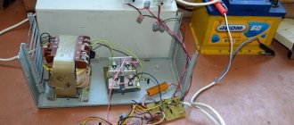
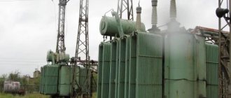
The purpose of thyristors can be very different, for example, a homemade welding inverter using thyristors, a charger for a car (thyristor in the power supply) and even a generator are very popular. Due to the fact that the device itself can pass both low-frequency and high-frequency loads, it can also be used for a transformer for welding machines (their bridge uses exactly these parts). To control the operation of the part in this case, a voltage regulator on the thyristor is needed.
Photo - using Thyristor instead of LATR
Don't forget about the ignition thyristor for motorcycles.
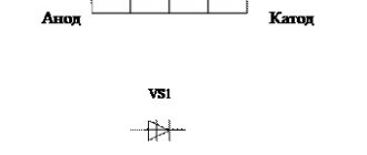
Description of design and principle of operation
The thyristor consists of three parts: “Anode”, “Cathode” and “Input”, consisting of three pn junctions that can switch between “ON” and “OFF” positions at very high speed. But at the same time, it can also be switched from the “ON” position for different durations, i.e., over several half-cycles, in order to deliver a certain amount of energy to the load. The operation of a thyristor can be better explained by assuming that it will consist of two transistors connected to each other, like a pair of complementary regenerative switches.
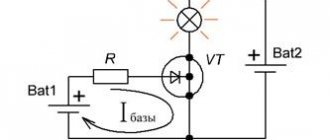
The simplest microcircuits demonstrate two transistors, which are combined in such a way that the collector current, after the “Start” command, flows into the NPN transistor TR 2 channels directly into the PNP transistor TR 1. At this time, the current from TR 1 flows into the channels into the bases of TR 2. These two interconnected transistors are arranged such that the base-emitter receives current from the collector-emitter of the other transistor. This requires parallel placement.
Photo - Thyristor KU221IM
Despite all safety measures, the thyristor may involuntarily move from one position to another. This occurs due to a sharp jump in current, temperature changes and other various factors. Therefore, before you buy a thyristor KU202N, T122 25, T 160, T 10 10, you need to not only check it with a tester (ring), but also familiarize yourself with the operating parameters.
Typical thyristor current-voltage characteristics
To start discussing this complex topic, look at the diagram of the current-voltage characteristics of a thyristor:
Photo - characteristics of the thyristor current-voltage characteristic
- The segment between 0 and (Vо,IL) fully corresponds to direct locking of the device;
- In the Vvo section, the thyristor is in the “ON” position;
- The segment between the zones (Vvo, IL) and (Vн,In) is the transition position in the on state of the thyristor. It is in this area that the so-called dinistor effect occurs;
- In turn, points (Vн,In) show on the graph the direct opening of the device;
- Points 0 and Vbr are the section where the thyristor is turned off;
- This is followed by the segment Vbr - it indicates the reverse breakdown mode.
Naturally, modern high-frequency radio components in a circuit can affect the current-voltage characteristics in an insignificant way (coolers, resistors, relays). Also, symmetrical photothyristors, SMD zener diodes, optothyristors, triode, optocouplers, optoelectronic and other modules may have different current-voltage characteristics.
Photo - current-voltage characteristic of a thyristor
In addition, we draw your attention to the fact that in this case, device protection is carried out at the load input.
Thyristor check
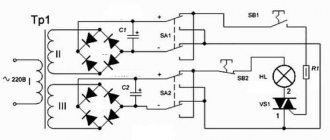
Before you buy a device, you need to know how to test a thyristor with a multimeter. The measuring device can only be connected to a so-called tester. The diagram by which such a device can be assembled is presented below:
Photo - thyristor tester
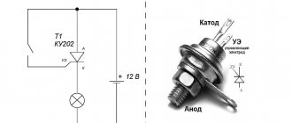
According to the description, it is necessary to apply a positive voltage to the anode, and a negative voltage to the cathode. It is very important to use a value that matches the resolution of the thyristor. The drawing shows resistors with a nominal voltage of 9 to 12 volts, which means that the tester voltage is slightly higher than the thyristor. After you have assembled the device, you can begin to check the rectifier. You need to press the button that sends pulse signals to turn it on.
Testing the thyristor is very simple; a button briefly sends an opening signal (positive relative to the cathode) to the control electrode. After this, if the running lights on the thyristor come on, the device is considered inoperative, but powerful devices do not always react immediately after the load arrives.
Photo - circuit tester for thyristors
In addition to checking the device, it is also recommended to use special controllers or a control unit for thyristors and triacs OWEN BOOST or other brands; it works approximately the same as a power regulator on a thyristor. The main difference is a wider range of voltages.
Video: operating principle of a thyristor
How does a thyristor do its job?
A thyristor is a controlled semiconductor device that is capable of quickly conducting current in one direction. The word controlled means a thyristor for a reason, since with its help, unlike a diode, which also conducts the total current to only one pole, you can select a separate moment when the thyristor begins the process of conducting current.
The thyristor has three current outputs at once:
To allow current to flow through such a thyristor, the following conditions must be met: the part must be located on the circuit itself, which will be under general voltage, and the required short-term pulse must be applied to the control part of the electrode. Unlike a transistor, controlling such a thyristor will not require the user to hold the control signal.
But all the difficulties of using such a device will not end there: the thyristor can be easily closed by interrupting the flow of current into it through the circuit, or by creating a reverse anode-cathode voltage. This will mean that the use of a thyristor in DC circuits is considered quite specific and in most cases completely unreasonable, and in AC circuits, for example, in a device such as a thyristor regulator, the circuit is created in such a way that the condition for closing the device is fully ensured . Any given half-wave will completely cover the corresponding section of the thyristor.
Specifications
Let's consider the technical parameters of the KU 202e series thyristor. This series presents domestic low-power devices, the main use of which is limited to household appliances: it is used to operate electric furnaces, heaters, etc.
The drawing below shows the pinout and main parts of the thyristor.
Photo - ku 202
- Set reverse on-state voltage (max) 100 V
- Closed voltage 100 V
- Pulse in open position - 30 A
- Repeated pulse in open position 10 A
- Average voltage <=1.5V
- Non-unlocking voltage >=0.2 V
- Set open current <=4 mA
- Reverse current <=4 mA
- Constant type unlocking current <=200 mA
- Set constant voltage <=7 V
- Turn-on time <=10 µs
- Turn-off time <=100 µs
The device turns on within microseconds. If you need to replace the described device, then consult a sales consultant at an electrical store - he will be able to select an analogue according to the diagram.
Photo - thyristor Ku202n
The price of a thyristor depends on its brand and characteristics. We recommend buying domestic devices - they are more durable and affordable. In spontaneous markets you can buy a high-quality, powerful converter for up to a hundred rubles.
T161-160-5
Description
| Type of shell | T161 |
| Repeating imp. arr. voltage (Urrm) and repeating pulse. closed voltage state (Udrm), V | 500 |
| Max. permissible environment current in open condition (Itav), A | 160 |
| Weight of goods, g. | 240 |
Thyristor marking
| T | 161 | 160 | 5 | T1 | A3 | UHL |
| 1 | 2 | 3 | 4 | 5 | 6 | 7 |
- T – Thyristor.
- Design (Housing type).
- Average current in open state; A.
- Voltage class; x100 V.
- Critical rate of voltage rise in the closed state (dvD/dt)crit.
- Group by shutdown time (by tq).
- Climatic performance.
(dvD/dt)crit - for low-frequency, avalanche, high-speed, pulse-frequency thyristors
| Group designation | Literal | 0 | P3 | E3 | A3 | P2 | K2 | E2 | F2 | T1 | P1 | M1 | K1 | H1 | E1 | C1 | IN 1 |
| Digital | 0 | 1 | 2 | 3 | 4 | 5 | 6 | 7 | 8 | — | 9 | — | — | — | — | — | |
| V/μs | meaning | not standardized | 20 | 50 | 100 | 200 | 320 | 500 | 1000 | 1600 | 2000 | 2500 | 3200 | 4000 | 5000 | 6300 | 8000 |
tq - for low-frequency, avalanche thyristors
| Group designation | Literal | 0 | AT 2 | C2 | E2 | H2 | K2 | M2 | P2 | T2 | X2 | A3 | AT 3 | C3 | E3 | H3 |
| Digital | 0 | — | — | 1 | — | — | 2 | — | 3 | — | 4 | — | 5 | — | — | |
| mks | meaning | not standardized | 800 | 630 | 500 | 400 | 320 | 250 | 200 | 160 | 125 | 100 | 80 | 63* | 50* | 40* |
Note: It is allowed to designate groups of devices with a digital code or a combination of digital and alphanumeric
* - only for devices with currents less than 100A
Characteristics of thyristor T161-160-5
| Thyristor name | Maximum permissible parameter values at Тп=25°С | Parameter values at Тп=25°С | Tj | ||||||||||||||
| IT(AV) | UDRM/URRM | IDRM/IRRM | ITSM | rT | (duD/dt)crit | (diT/dt)crit | UTM | UT(TO) | IL | IH | I.G.T. | UGT | td | tq | Rthjc | ||
| A | IN | mA | A | MOhm | V/μs | A/mks | IN | IN | mA | mA | mA | IN | mks | mks | °C/W | °C | |
| T161-160-3 | 160 | 300 | 15 | 4000 | 1,36 | 200…1000 | 80 | 1,7 | 1,05 | 700 | 250 | 200 | 3,5 | 5 | 160 | 0,15 | -60…+125 |
| T161-160-4 | 160 | 400 | 15 | 4000 | 1,36 | 200…1000 | 80 | 1,7 | 1,05 | 700 | 250 | 200 | 3,5 | 5 | 160 | 0,15 | -60…+125 |
| T161-160-5 | 160 | 500 | 15 | 4000 | 1,36 | 200…1000 | 80 | 1,7 | 1,05 | 700 | 250 | 200 | 3,5 | 5 | 160 | 0,15 | -60…+125 |
| T161-160-6 | 160 | 600 | 15 | 4000 | 1,36 | 200…1000 | 80 | 1,7 | 1,05 | 700 | 250 | 200 | 3,5 | 5 | 160 | 0,15 | -60…+125 |
| T161-160-7 | 160 | 700 | 15 | 4000 | 1,36 | 200…1000 | 80 | 1,7 | 1,05 | 700 | 250 | 200 | 3,5 | 5 | 160 | 0,15 | -60…+125 |
| Т161-160-8 | 160 | 800 | 15 | 4000 | 1,36 | 200…1000 | 80 | 1,7 | 1,05 | 700 | 250 | 200 | 3,5 | 5 | 160 | 0,15 | -60…+125 |
| T161-160-9 | 160 | 900 | 15 | 4000 | 1,36 | 200…1000 | 80 | 1,7 | 1,05 | 700 | 250 | 200 | 3,5 | 5 | 160 | 0,15 | -60…+125 |
| T161-160-10 | 160 | 1000 | 15 | 4000 | 1,36 | 200…1000 | 80 | 1,7 | 1,05 | 700 | 250 | 200 | 3,5 | 5 | 160 | 0,15 | -60…+125 |
| T161-160-11 | 160 | 1100 | 15 | 4000 | 1,36 | 200…1000 | 80 | 1,7 | 1,05 | 700 | 250 | 200 | 3,5 | 5 | 160 | 0,15 | -60…+125 |
| T161-160-12 | 160 | 1200 | 15 | 4000 | 1,36 | 200…1000 | 80 | 1,7 | 1,05 | 700 | 250 | 200 | 3,5 | 5 | 160 | 0,15 | -60…+125 |
| T161-160-13 | 160 | 1300 | 15 | 4000 | 1,36 | 200…1000 | 80 | 1,7 | 1,05 | 700 | 250 | 200 | 3,5 | 5 | 160 | 0,15 | -60…+125 |
| T161-160-14 | 160 | 1400 | 15 | 4000 | 1,36 | 200…1000 | 80 | 1,7 | 1,05 | 700 | 250 | 200 | 3,5 | 5 | 160 | 0,15 | -60…+125 |
| T161-160-15 | 160 | 1500 | 15 | 4000 | 1,36 | 200…1000 | 80 | 1,7 | 1,05 | 700 | 250 | 200 | 3,5 | 5 | 160 | 0,15 | -60…+125 |
| T161-160-16 | 160 | 1600 | 15 | 4000 | 1,36 | 200…1000 | 80 | 1,7 | 1,05 | 700 | 250 | 200 | 3,5 | 5 | 160 | 0,15 | -60…+125 |
| T161-160-17 | 160 | 1700 | 15 | 4000 | 1,36 | 200…1000 | 80 | 1,7 | 1,05 | 700 | 250 | 200 | 3,5 | 5 | 160 | 0,15 | -60…+125 |
| T161-160-18 | 160 | 1800 | 15 | 4000 | 1,36 | 200…1000 | 80 | 1,7 | 1,05 | 700 | 250 | 200 | 3,5 | 5 | 160 | 0,15 | -60…+125 |
Explanation of symbols in the tables:
- IT(AV) — Maximum permissible average current in the open state.
- UDRM - Maximum off-state repetitive impulse voltage.
- URRM — Maximum repetitive pulse reverse voltage.
- IDRM - Off-state repetitive pulse current.
- IRRM - Repetitive pulse reverse current.
- ITSM - On-State Surge Current.
- rT — Dynamic resistance of the thyristor.
- (dVD/dt)crit — Critical rate of voltage rise in the closed state.
- (diT/dt)crit — Critical rate of current rise in the open state.
- UTM - On-state impulse voltage.
- UT(TO) — Thyristor threshold voltage.
- IL — Thyristor turn-on current.
- IH - Thyristor holding current.
- IGT - Unlocking constant control current.
- UGT - Unlocking constant control voltage.
- td — Turn-on delay time.
- tq — Shutdown time.
- Rthjc — Thermal resistance of the thyristor junction-body.
- Tj — Thyristor junction temperature.