The simplest calculation of power transformers and autotransformers
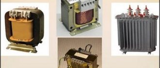
Sometimes you have to make your own power transformer for the rectifier.
In this case, the simplest calculation of power transformers with a power of up to 100-200 W is carried out as follows. Knowing the voltage and the maximum current that the secondary winding (U2 and I2) should give, we find the power of the secondary circuit: If there are several secondary windings, the power is calculated by adding the powers of the individual windings.
Next, taking the efficiency of a small power transformer equal to about 80%, we determine the primary power:
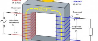
Power is transferred from the primary winding to the secondary winding through the magnetic flux in the core. Therefore, the cross-sectional area of the core S depends on the power value P1, which increases with increasing power. For a core made of normal transformer steel, S can be calculated using the formula:
where s is in square centimeters, and P1 is in watts.
The value of S determines the number of turns w' per volt. When using transformer steel
If you have to make a core from steel of poorer quality, for example from tin, roofing iron, steel or iron wire (they must first be annealed so that they become soft), then S and w' should be increased by 20-30%.
Now you can calculate the number of turns of the windings
In load mode there may be a noticeable loss of part of the voltage across the resistance of the secondary windings. Therefore, for them it is recommended to take the number of turns 5-10% more than calculated.
Primary current
The diameters of the winding wires are determined by the current values and based on the permissible current density, which for transformers is taken on average 2 A/mm2. At this current density, the diameter of the wire without insulation of any winding in millimeters is determined from the table. 1 or calculated by the formula:
When there is no wire of the required diameter, you can take several thinner wires connected in parallel. Their total cross-sectional area must be no less than that corresponding to the calculated one wire. The cross-sectional area of the wire is determined according to the table. 1 or calculated by the formula:
For low voltage windings, which have a small number of turns of thick wire and are located on top of other windings, the current density can be increased to 2.5 and even 3 A/mm2, since these windings have better cooling. Then in the formula for the wire diameter, the constant coefficient instead of 0.8 should be 0.7 or 0.65, respectively.
Finally, you should check the placement of the windings in the core window. The total cross-sectional area of the turns of each winding is found (by multiplying the number of turns w by the cross-sectional area of the wire equal to 0.8d2iz, where diz is the diameter of the wire in the insulation. It can be determined from Table 1, which also indicates the mass of the wire. The cross-sectional areas of all windings are added To take into account the approximate looseness of the winding and the influence of the frame of insulating spacers between the windings and their layers, it is necessary to increase the found area by 2-3 times.The area of the core window should not be less than the value obtained from the calculation.
As an example, let's calculate a power transformer for a rectifier that powers a device with vacuum tubes. Let the transformer have a high-voltage winding designed for a voltage of 600 V and a current of 50 mA, as well as a winding for incandescent lamps with U = 6.3 V and I = 3 A. The mains voltage is 220 V.
We determine the total power of the secondary windings:
Primary circuit power
Find the cross-sectional area of the transformer steel core:
Number of turns per volt
Primary current
The number of turns and diameter of the wires of the windings are equal:
• for the primary winding
• for step-up winding
• for filament windings of lamps
Let us assume that the core window has a cross-sectional area of 5×3 = 15 cm2 or 1500 mm2, and the selected wires have the following insulated diameters: d1iz = 0.44 mm; d2iz = 0.2 mm; d3iz = 1.2 mm.
Let's check the placement of the windings in the core window. Find the cross-sectional area of the windings:
• for the primary winding
• for step-up winding
• for filament windings of lamps
The total cross-sectional area of the windings is approximately 430 mm2.
As you can see, it is more than three times smaller than the window area and, therefore, the windings will fit.
The calculation of an autotransformer has some features. Its core should not be calculated for the full secondary power P2, but only for that part of it that is transmitted by the magnetic flux and can be called the transformed power Pm.
This power is determined by the formulas:
- for step-up autotransformer
- for a step-down autotransformer, and
If the autotransformer has taps and will operate at different values of n, then in the calculation it is necessary to take the value of n that is most different from unity, since in this case the value of Pm will be the largest and it is necessary that the core can transmit such power.
Then the design power P is determined, which can be taken equal to 1.15•Rm. The 1.15 multiplier here takes into account the efficiency of the autotransformer, which is usually slightly higher than that of the transformer. D
Next, the formulas for calculating the cross-sectional area of the core (based on power P), the number of turns per volt, and wire diameters indicated above for the transformer are applied. It should be borne in mind that in the part of the winding that is common to the primary and secondary circuits, the current is equal to I1 - I2 if the autotransformer is step-up, and I2 - I1 if it is step-down.
What is affected by the number of turns in a transformer?
If we talk about the secondary windings of the transformer, then the value of the number of turns in them mainly affects the output voltage. Things are more complicated with the primary winding, since the voltage on it is set by the supply network. The parameters of the primary winding affect the no-load current, and, consequently, the efficiency. When changing the parameters of the primary winding, it will be necessary to recalculate all secondary windings.
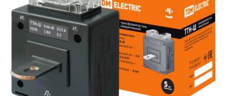
And it is worth noting that it is better not to open the secondary winding of the CT.
Simple calculation of a step-down transformer.
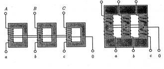
The magnetic core of the low-frequency transformer consists of steel plates. Using laminations instead of a solid core reduces eddy currents, which increases efficiency and reduces heat.
Magnetic cores of type 1, 2 or 3 are produced by stamping. Magnetic cores of types 4, 5 or 6 are produced by winding a steel tape onto a template, and magnetic cores of types 4 and 5 are then cut in half.
1, 4 – armored, 2, 5 – rod, 6, 7 – ring.
To determine the cross-section of the magnetic circuit, you need to multiply the dimensions “A” and “B”. For calculations in this article, the section size in centimeters is used.
Transformers with twisted rod position 1 and armored magnetic cores position 2.
Transformers with stamped armored magnetic cores, position 1, and core magnetic cores, position 2.
Transformers with twisted ring magnetic cores.
The overall power of a transformer can be approximately determined by the cross-section of the magnetic core. True, the error can be up to 50%, and this is due to a number of factors. The overall power directly depends on the design features of the magnetic core, the quality and thickness of the steel used, the size of the window, the amount of induction, the cross-section of the winding wire and even the quality of the insulation between the individual plates.
The cheaper the transformer, the lower its relative overall power. Of course, it is possible through experiments and calculations to determine the maximum power of a transformer with high accuracy, but there is not much point in this, since during the manufacture of the transformer, all this is already taken into account and reflected in the number of turns of the primary winding. So, when determining the power, you can be guided by the cross-sectional area of the set of plates passing through the frame or frames, if there are two of them.
Where:
P
– power in Watts,
B
– induction in Tesla,
S
– cross section in cm²,
1.69
– constant coefficient.
First, we determine the cross-section, for which we multiply the dimensions A and B.
Then we substitute the cross-sectional size into the formula and get the power. I chose 1.5Tc induction, since I have an armored twisted magnetic circuit.
If you need to determine the required cross-sectional area of the manipulator based on the known power, you can use the following formula:
It is necessary to calculate the cross-section of an armored stamped magnetic circuit for the manufacture of a 50-watt transformer.
The magnitude of induction can be found in the table. You should not use maximum induction values, as they can vary greatly for magnetic cores of different quality.
Maximum indicative values of induction.
HOW TO CALCULATE A STEP-DOWN TRANSFORMER.
In a household, it may be necessary to equip lighting in damp areas: basement or cellar, etc. These rooms have an increased risk of electric shock.
In these cases, you should use electrical equipment designed for a reduced supply voltage, no more than 42 volts. You can use a battery-powered electric flashlight or use a step-down transformer from 220 volts to 36 volts.
As an example, let's calculate and manufacture a single-phase 220/36 volt power transformer. To illuminate such rooms, a 36-volt electric light bulb with a power of 25-60 watts is suitable. Such light bulbs with a base for a standard socket are sold in electrical goods stores.
Calculation method
The full calculation of the transformer is quite complex and takes into account the following parameters:
- supply voltage and frequency;
- number of secondary windings;
- current consumption of each secondary winding;
- type of core material;
- weight and size indicators.
At the household level, for the manufacture of devices powered by a standard 220V 50Hz network, the design can be significantly simplified.
The technique does not require special knowledge of complexity, and if you have experience, it takes little time.
The following data is required for the calculation:
- Number of exits.
- Voltage and current consumption of each winding.
The design of any transformer is based on the total power of all secondary loads:
Pс=I1∙U1+ I2∙U2+… In∙Un
To take into account losses, the concept of overall power has been introduced, for the calculation of which a simple formula is used:
P=1.25∙ Pс
Knowing the power, you can determine the core cross-section:
S=√P
The resulting cross-sectional value will be expressed in square centimeters!
Further calculations depend on the type and material of the selected core. Magnetic cores are of the following types:
- armored;
- rod;
- O-shaped.
The methods for manufacturing magnetic cores also differ:
- typesetting - from individual plates;
- twisted, split or solid.
Armored or rod magnetic cores are usually split, while O-shaped ones are structurally made exclusively in one piece. In this respect, they are no different from continuous rod cores.
To determine the number of turns, use the following ratio, showing how many turns are needed per 1 volt of voltage:
W=K/S,
where K is a coefficient that depends on the material and type of core.
To simplify calculations, the following coefficient values are adopted:
- For stacked magnetic cores made of W- or U-shaped plates K=60.
- For split magnetic cores K=50.
- For O-shaped cores K=40.
As you can see, the shortest length of the winding wire, and therefore the best weight and size indicators, will be for O-shaped cores. In addition, designs with such cores have a small field of parasitic magnetic scattering and maximum efficiency. They are rarely used only because it is technically difficult to wind a winding around a closed core.
Knowing the parameter W, it is easy to determine the number of turns for each winding:
n=U∙W
To take into account the voltage drop on the primary winding, wound with a large amount of thin wire, the number of turns in it should be increased by 5%. This is especially true for small-sized, low-power structures.
You can reduce the no-load current by increasing the W value for each of the windings, but you should be aware that an excessive increase can lead to saturation of the magnetic circuit, which will lead to a sharp increase in the no-load current and a decrease in the output voltage.
At the final stage, the diameter of the conductors of each winding is determined. The calculation formula is as follows:
d=0.7√I
The diameter of the winding wire is determined for all windings without exception.
The resulting values are rounded to the nearest larger standard wire diameter.