The thickness of the walls of the ground floor and basement - calculation features
Correct calculation of a basement wall involves taking into account the influence of many factors.
In particular, this is the groundwater level on the site, the type of soil, the height of the future building, materials used for construction, etc. It is recommended to entrust all design work to specialists. However, for a general understanding of the calculation technology, you can use the information below. If there is a basement or ground floor, the shallow strip foundation of the house automatically becomes recessed. In other words, it will be a full-fledged wall underground, and not just a foundation for a building.
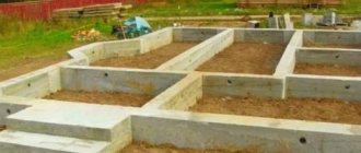
Foundation for a building with a basement
If the basement is made after the construction of the main structure, then the following rule must be observed: the voids formed after excavation should not fall within the 45-degree projection of the base of the strip foundation on one side or the other.
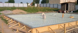
The foundation must have a sufficiently wide base.
The foundation should be made as strong and reliable as possible so that its walls can successfully withstand horizontal shifts due to the pressure of the surrounding soil. It is recommended to use a monolithic concrete pad connected to the tape with a reinforcement cage as the foundation base. Since the weight of the foundation is quite large, the sole should be made wide.
Soil pressure on the basement wall.
When planning the construction of a basement floor, which will later become a living room, it should be taken into account that high walls (200 cm or more) located underground will experience significant pressure from the ground during the entire period of operation. Therefore, during the construction of a basement, special attention should be paid to the reinforcement of the concrete wall.
The spacing between the reinforcing bars in the wall frame should not be too large. It is recommended to make it less than 40 cm horizontally and vertically. The frame of the wall must be connected to the frame of the foundation cushion. In addition, it is necessary to follow the rules for reinforcing corners and wall junctions.
A monolithic reinforced concrete wall is the best option in terms of strength, durability and resistance to soil pressure. This design is more reliable than, for example, block or brick.
Additional strengthening of the structure is achieved by constructing intersecting internal walls of the basement under the internal walls of the structure.
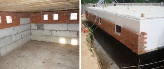
Basement walls
When making monolithic foundations, the construction of walls should begin only after the concrete has completely hardened and gained the necessary strength.
The height of the walls depends on the design and purpose of the basement. For utility and storage basements, a height of two meters is sufficient, and for residential premises - a minimum of 2.5 m.
Correct calculation of the thickness of the basement walls takes into account all factors affecting the foundation:
- soil water level;
- type of soil;
- height of the house;
- foundation wall material.
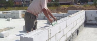
The most optimal design is considered to be walls made of monolithic reinforced concrete. This type has an advantage over block or brick walls, since it has greater strength, durability and reliability.
If concrete blocks are used in the construction of walls, then additional reinforcement should be made when laying them, and a reinforced concrete belt should be constructed along the top.
Important! Blocks can only be used made of concrete grades of at least M-150.
When brick cladding the walls of a building, it can be extended to the basement part. The thickness of the above-ground section of the basement wall can be reduced to 0.09 m. Brick cladding is secured to the basement walls with metal ties at a distance of no more than 0.2 m vertically and no more than 0.9 m horizontally. The space between the basement walls and the facing coating is filled with cement mortar.
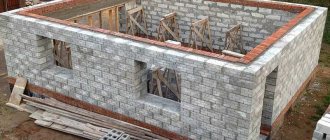
Concreting basement walls
Minimum permissible basement wall thickness
Building codes stipulate the minimum permissible dimensions for the thickness of foundation walls, depending on the materials used.
The wall thickness can be calculated using the table based on the depth of the basement:
When using this table to calculate the thickness of basement walls, use the first column, “Unsupported Structure,” if the floors are on a solid wall. The same applies to fixing floor beams using anchor bolts. In cases where the wall has an opening or several non-reinforced ones around the perimeter, the calculation is carried out according to the second column “Structure with lateral support”. The wall will be more stable the shorter it is.| Basement depth in meters | |||
| Material | Support-free design | Side support design | Min. permissible thickness |
| Monolithic concrete grade B 12.5 | 0,8 | 1,5 | 0,15 |
| 1,2 | 2,15 | 0,20 | |
| 1,4 | 2,3 | 0,25 | |
| 1,5 | 2,3 | 0,30 | |
| Monolithic concrete grade B15 | 0,8 | 1,8 | 0,15 |
| 1,2 | 2,3 | 0,20 | |
| 1,4 | 2,3 | 0,25 | |
| 1,5 | 2,3 | 0,30 | |
| Block (concrete or foam concrete) | 0,6 | 1,8 | 0,14 |
| 1,9 | 1,2 | 0,19 | |
| 1,2 | 2,8 | 0,24 | |
| 1,4 | 2,2 | 0,29 | |
Minimum wall thickness
Depending on the materials used in construction, as well as the depth of the underground room, there are minimum values for the thickness of basement walls, as well as the width of the foundation base.
Calculation of the thickness of basement walls during construction from various materials (minimum values).
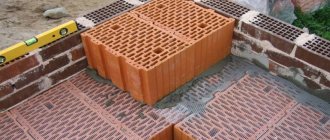
If the basement walls are built from small-sized building blocks (for example, expanded clay concrete), then the masonry must be strengthened with the help of longitudinal reinforcement and an armored belt laid along the upper border of the masonry. As for prefabricated concrete blocks, you need to take into account the fact that only those made using concrete M150 and higher are suitable for the foundation of a house with a basement.
The width of the walls and the dimensions of the base of the foundation made of monolithic concrete and blocks.
The table above assumes that:
- Walls are supported laterally if the basement ceiling beams rest on the top of the basement wall.
- If there is a gap (opening) in the wall more than 120 cm wide, or several gaps, the total width of which is more than 1/4 of the length of the wall, and there is no reinforcement along the contour of these gaps, the part of the wall under the opening is calculated as having no lateral support. If the width of the wall sections is less than the width of the gaps, then the entire wall is considered as one large opening.
These criteria must be taken into account when making calculations for the basement wall. The structure must have good stability. You should also remember one of the construction rules - the stability of the wall directly depends on its length. The shorter it is, the stronger and more reliable the structure.
Expansion joints
For large basements (the length of the walls is more than 25 meters), it is necessary to install special expansion joints, which will be located at a distance of 15 meters or less from each other. In addition, seams must be present in places where there are differences in the height of the structure. Their design must provide protection against moisture penetration into the basement.
Distance from cladding to ground
If the exterior decoration of the house is done with brick, then the decorative masonry can be continued on the part of the basement wall that protrudes above the ground (the upper part of the basement wall must rise at least 15 cm above the ground surface).
The thickness of the above-ground part of the basement wall in this case can be reduced to 9 cm. The facing masonry is attached to the concrete wall using special ties. The distance between the ties should not be too large: up to 90 cm horizontally and up to 20 cm vertically. The free space between the wall and the facing masonry is filled with mortar.
If the cladding of the first floor is made of wood or by plastering over heat-insulating material or lathing, then there should be a gap of 25 cm or more from the lower border of the cladding to the ground.
The answer will be something like this:
Selecting a design scheme that most closely matches the operating conditions of the structure, especially when it comes to foundations and soils, is not an easy task. With the specified building structure (there is a basement floor - a reinforced concrete slab and there is a floor slab, somehow connected to the foundation wall), the design scheme shown in Figure 418.1 is really the most acceptable, since both the floor slab and the basement floor can be considered as hinged supports beams that do not interfere with the rotation of the cross sections of the beam, but only prevent horizontal displacement on the supports, since the modulus of elasticity of the slab and floor material is significantly greater than the modulus of elasticity of the soil.
Thus, the adopted design scheme allows for the simplest possible calculation and provides the highest possible safety margin.
In general, the calculation comes down to checking the wall for strength and stability, since in this case the outer foundation wall is considered not only as a beam, but also as a rack with the same hinged supports.
If the calculation according to such a design scheme seems too simple to you, and the possible safety margin is excessive, then to perform more accurate calculations you should take into account the following factors:
1. It is more correct to consider this foundation wall not as a rod with hinged supports, but as a plate with hinged supports along the contour.
Or like a plate with hinged supports at the top and bottom and rigid pinching on the sides. Foundation walls perpendicular to the one in question may be considered as hinged lateral supports or even as rigid pinching depending on the overall structure of the building.
The influence of this factor is greater, the smaller the ratio of wall length to height l/H1. If this ratio tends to infinity, then the influence of this factor tends to zero, at least for the section of the wall under consideration, the one farthest from the perpendicular walls. In other words, the greater the length of the foundation wall compared to the height, the closer the adopted design scheme is to the actual operation of the structure.
2. As a result of the redistribution of stresses in the material of the foundation wall, partial pinching may occur on the upper and lower conditional supports.
In general, the influence of this factor is very insignificant.
3. Possible deformations of both the floor and the slab during compression should be taken into account.
These deformations can lead to a change in the geometry of the system under consideration, and therefore to a change in the acting loads. As a rule, these deformations are relatively small, so the influence of this factor can be neglected.
Reinforcement cage
The walls of the basement or basement, as mentioned earlier, need additional strengthening with the help of a reinforcement frame. An important quality of such a frame is its elasticity. This is why it is recommended to use knitted reinforcing bars rather than a rigid welded connection.
During the operation of the building, some movement of the foundation occurs. This happens during heavy rainfall or during frost heaving of the soil. The reinforcement frame inside the underground walls will be subject to severe stress. Nothing will happen to the interconnected rods under such conditions, while the welding joint simply breaks under significant pressure. And repairs in such situations are extremely difficult and expensive.
The reinforcement cage is tied in those places where the metal rods intersect. To perform this work, you need to use a special wire designed for tying reinforcement. In fact, it can be any wire whose diameter exceeds 2-3 mm. The work is done with a special hook or gun.
Rust on the rods
You should not use used metal rods, because old reinforcement in some cases has defects that may appear during operation. Savings when purchasing materials in this case are not justified.
If the new metal rods have traces of rust, then there is nothing to worry about. Do not attempt to remove rust or paint over it. Such manipulations will negatively affect the adhesion of the reinforcement to the concrete. When constructing a frame from reinforcement, metal rods can be cut using a grinder.
To bend the rods, you can use special devices for heating the metal on site. However, if possible, this approach should be abandoned, because during the heating process the structure of the metal changes, and this negatively affects its performance characteristics.
It is not allowed to install a reinforcement structure into a formwork where concrete has already been poured. If the stages of work were mixed up, then the whole process is carried out again: the mortar is removed, the formwork is completely dismantled, cleaned and installed again, a metal frame is laid in it and then a new mortar is poured.
Extension of reinforcement frame
It is not recommended to carry out work on building up the reinforcement structure in a horizontal or vertical direction. This is due to the fact that under significant loads, breaks may form at the joints.
Increasing the reinforcement frame is permitted only in cases where the basement walls will not experience significant loads during operation (light building materials, low groundwater levels, etc.).
Reinforcing walls yourself is not always easy. Especially if you have not previously been involved in construction and do not have the required skills and abilities. It is recommended to hire professional builders for this work.
The thickness of the basement walls, the diameter of the reinforcement used and the amount of building materials must be determined in advance, taking into account the operating characteristics of the structure, the groundwater level and other factors.
Website editor-in-chief, civil engineer. He graduated from SibSTRIN in 1994, since then he worked for more than 14 years in construction companies, after which he started his own business. Owner of a company engaged in suburban construction.
The calculation algorithm itself may look something like this:
As a rule, to simplify calculations, 1 linear meter of the length of the foundation wall is considered. It is this linear meter that is considered as a rack or as a beam having a width of 1 meter.
The longitudinal force N1 acting on the outer foundation wall - a rack with hinged supports - is determined.
This force can be applied with an eccentricity e1 relative to the neutral axis of the post, for example with a building structure such as shown in Figure 418.1.
The concentrated load N1 includes:
1.1. Self-weight of the overlying walls.
An example of determining the load due to its own weight is given separately.
1.2. Load from interfloor floors (except for the floor above the basement).
How this load is determined is discussed in more detail in paragraph 2, where the load from the floor above the basement is considered.
1.3. Roof load.
To determine this load, you need to know not only snow and wind loads, but also the roof structure.
Under the action of load N1 applied with eccentricity e1 bending moments will act in the cross sections of the rack with hinged supports. The diagram reflecting changes in moments along the length of the rack due to the action of this load is designated as M1 .
The maximum value of the moment under the action of a longitudinal force applied with eccentricity will be on the upper support and will be:
М1max = N1e1 (418.1.1)
At the lower support the moment will be zero, and to determine the value in any other section, you need to multiply the value of equation (418.1) by (1 - x/H1):
M1(x) = N1e1(1 - x/H1) (418.1.2)
where x is the distance from the upper support to the section under consideration.
Note: we would get the same results if we considered not a rack with hinged supports, but a beam with hinged supports, on one of which a bending moment was applied.
The load Q from the floor above the basement is determined.
In general, load Q is the support reaction determined when calculating a beam or slab supported along the contour, if this floor is monolithic the size of the room. In this case, the outer foundation wall is one of the supports of such a beam or slab.
, both a beam and a slab can be either single-span or multi-span, and this should be taken into account when determining the load Q. More details in the Beams and Plates sections.
To simplify calculations, the value of the support reaction of a multi-span beam at the outer support can be taken as for a single-span beam, this will lead to an additional safety margin. With a monolithic floor slab supported along the contour, the value of the support reaction can be determined from the tables.
In the vast majority of cases, the load Q is applied to the rack with eccentricity e2 . And not only because the floor usually rests only on part of the foundation wall, as shown in Figure 418.1, but also because under the influence of the load on the slab, stress is redistributed on the supporting area of the foundation wall.
This should be taken into account when determining the value of eccentricity e2 . To simplify calculations, this value can be taken equal to 2/3 of the length of the supporting section of the slab.
As in the case of the longitudinal force N1 , under the action of the longitudinal force Q, a bending moment acts in the cross sections of the foundation wall-rack. The rules for determining this moment are the same as in paragraph 1 with the only difference being that the stretched section zone will be on the opposite side, which is reflected in diagram M2 .
The distributed uniformly varying horizontal load q on the rack is determined.
This load includes:
3.1. Load from the soil's own weight.
At first glance, this seems strange, because the load from the soil’s own weight is directed vertically downwards and should not be transferred to the wall. However, there is nothing strange about this. The fact is that the soil, like any other physical body, under the influence of a load is compressed in the vertical direction, but at the same time it tries to maintain its volume and therefore expands in the horizontal direction. This is where the horizontal component of the load on the foundation wall arises.
To determine this horizontal component, it is necessary to know the physical characteristics of the soil that will be used for backfill. In particular, the density γ and the angle of internal friction f (in fact, this angle is usually denoted by the Greek letter φ and the same letter denotes the buckling coefficient, which is discussed below, so to avoid confusion, I denoted the angle of internal friction with the letter f )
The smaller the angle of internal friction, the smaller the horizontal component of the load on the foundation wall. Depending on the composition and moisture content of the soil used for backfilling, the angle value can vary between 20-45°.
In order not to bother with the exact determination of the angle of internal friction, especially in the absence of geological exploration results, which happens quite often in low-rise private construction, I recommend taking the angle φ = 45° for calculations, i.e. consider soil as a conditional liquid. This will not only provide a possible safety margin, but will also significantly simplify the calculations. In this case, the value of the load acting in any cross section of the rack below the top of the ground can be determined using the following formula:
q(x) = gγ(x - a) (418.2)
where g = 9.81 m/s2 is the acceleration of free fall. a = H1 - H2 - the distance between the upper support of the rack and the mark of the top of the ground (not shown in the design diagram).
Note : the load value determined by formula (418.2) will be in Pascals. If the calculation is carried out in kilogram-forces, then the value of the plane load can be determined using a simplified formula (do not multiply the right side of the formula by g). In addition, the load should be converted from flat to linear, i.e. multiply by 1 linear meter of the length of the wall, which is the width of our beam.
3.2. Load p on the covering or blind area outside the foundation wall.
Since this load will lead to a conditionally uniform compression of the underlying soil, it can be considered as uniformly distributed from the lower support to the surface mark.
If the loads p and q are added, which the superposition method allows us, then the value of the total load at a distance a from the upper support will be equal to:
Σqa = р + 0 = q1 (418.3.1)
and on the lower support:
Σqmax = р + gγH2 = q2 (418.3.1)
Which is shown on the load diagram
3.3. The load from the own weight of the covering or blind area.
If the density of the coating or blind area is significantly greater than the density of the soil located below, then this should be taken into account in the calculations; accordingly, the load diagram should have a slightly different appearance.
As a rule, the density of the blind area or coating is comparable to the accepted density of the soil, and in addition, the thickness of the layer of the blind area or coating, which has a higher density, is tens of times less than the height of the wall, and therefore, to simplify calculations, this influence on the general appearance of the load diagram can be neglected.
You can also consider the difference in the densities of the blind area and soil as part of the load p .
The change in moments acting in the cross sections of the rack under the influence of a horizontal load is shown in the diagram Mq .
Note : To further simplify the calculations, the load q , uniformly varying from the minimum value q1 to the maximum q2 along the height H2 , can be considered as uniformly varying from 0 to the maximum value along the entire height of the wall H1 . In this case, to determine the values of the moment in the section under consideration, you can use ready-made calculation schemes for such a special case. If the load on the coating is sufficiently large or the coating is almost flush with the top support of the rack, then in this case the superposition method should be used.
The value of the moment and longitudinal force in the most loaded section is determined.
In fact, this is not as easy to do as it might seem at first glance, because the most loaded section should be determined taking into account the stability of the rack.
Those. from the point of view of loss of stability, the most dangerous sections are approximately in the middle of the height of the rack, and meanwhile the maximum moment will act approximately at a distance H1/4 from the lower support of the rack, as can be seen from the summary diagram ΣM .
In this regard, it is recommended to consider the section located at a distance of H1/3 from the lower support of the rack as the most loaded.
The value of the moment in this section can be determined from the moment diagram (if one will be constructed) or by calculation. The value of the longitudinal force acting in the section under consideration will be equal to:
ΣNx = N1 + Q + N2(x) (418.4)
where N2(x) is the load from the own weight of the foundation wall in the section under consideration. The value of this load is determined approximately the same as for the overlying walls.
The buckling coefficient φ is determined.
An example of determining the buckling coefficient is given separately.
Selection of materials
If you intend to use the basement as an additional living space, then even at the project stage you should think about the choice of materials. Monolithic underground walls have the highest strength and low water resistance, while bricks or blocks cannot provide a similar level of waterproofing due to the presence of seams and joints.
The concrete partition itself has a fairly high level of strength, but to achieve the technical strength characteristics according to the standard, a very large amount of concrete will be required, which will lead to an inevitable increase in construction costs. And adding metal elements to the solution will strengthen the concrete layer without excessive thickening.
Basic requirements for the walls of the basement
Foundation walls must be resistant to horizontal movement due to the pressure of the surrounding soil. It is recommended to use a concrete monolith cushion, belted with a reinforcement cage, as the base of the foundation.
The basement floor does not provide for the placement of living rooms if its upper ceiling rises less than two meters above ground level. Otherwise, such a basement is considered a ground floor. When planning the arrangement of a basement as a living area, it is important to take into account that high underground walls will experience significant pressure from the soil over the entire surface.
They will need to be additionally reinforced. The spacing between the reinforcement bars in the frame should not be excessively large - up to 40 cm horizontally and vertically will be sufficient. The frame is certainly connected to the foundation cushion.
It is especially important to follow the rules for reinforcing corners and surface junctions. The structure can be strengthened in terms of reliability and strength by building basement partitions, which will distribute the load on the supporting walls.
Important! The most reliable option for strength and resistance to soil pressure is a monolithic concrete wall reinforced with reinforcement. Its durability, hydro- and thermal insulation characteristics are many times higher than those made from blocks or bricks.
Basement wall thickness
The thickness of the walls of the basement directly depends on the building materials used and the depth of the underground structure. When used as a residential area, the height should be 2.5-3 meters; if technical premises are located, a value of 1.8-2.2 meters will be sufficient. It is necessary to provide a reserve for floor screed and finishing work.
The wall thickness is calculated taking into account the groundwater level. If the groundwater is far enough from the base, it is recommended to adhere to the following requirements: the lower wall may not be strong and protrude 10 cm beyond the contour of the building, and the thickness of the basement walls at a placement depth of 1.5-2.5 meters can be from 20 to 40 cm.
If the base is located below the groundwater level, then the base slab must be reinforced, have a thickness of 20 cm and extend beyond the building frame by 40 cm.
There are approved standards for the minimum values of basement walls, which are regulated by SNiP 2.09.03-85, “Design of retaining walls and basement walls.”
When laying a basement from small-format blocks, for example, expanded clay concrete, it is necessary to reinforce it with longitudinal reinforcement and a special belt over the entire masonry. In the case of prefabricated concrete blocks, the requirements for the grade of manufacture are observed - the use of concrete M150 and higher.
- When calculating the basement walls, you should remember the following design features: The wall has lateral support if the ceiling beams of the basement rest on its upper part;
- If there is an opening in the wall of more than 1.2 m (or several, with a total width of more than a quarter of the entire length), then in the absence of reinforcement it is considered that it does not have lateral support;
- If the width of the wall sections is less than the width of the void spaces, then the entire wall is considered as one large opening.
In any case, the structure should be as stable as possible. Moreover, stability directly depends on its length - the shorter it is, the more reliable it is.
Arrangement of expansion joints
In basements with a length of more than 25 m, it is necessary to provide for a special location of special expansion joints. Their relative position should be about 15 meters. In addition, such seams should be provided in all places with differences in height of the structure. This will provide protection from moisture entering the room.
Requirements for facing work
When externally facing with brick, decorative masonry can also be laid on part of the protruding basement wall, taking into account its height above the ground - the value should be at least 15 cm above the ground surface. In this case, the thickness of the ground part of the basement wall can be reduced by 9 cm.
The facing masonry is attached to the concrete with special ties. The distance between them should not exceed 90 cm horizontally and 20 cm vertically. The resulting gap between the wall and the facing masonry is filled with mortar.
When covering the base with wood or decorative plaster over a heat-insulating or waterproofing layer, there should be a gap of at least 25 cm from the bottom border of the cladding to the ground surface.
Strengthening with reinforced frame
As a rule, a basement wall is created using reinforcing mesh, the main feature of which is elasticity. When creating it, experts recommend using the knitting method rather than welding, since in the event of a violation of the position of the foundation (displacement, damage), the knitted reinforcing mesh will be able to maintain its integrity, while the welded structure cannot withstand the places where the elements are attached to each other.
When making a mesh, it is important to correctly determine the cell dimensions. For basements, this value can range from 25 cm to 35 cm. Moreover, it is important to know that the smaller the link (cell), the more reliable and durable the effect of strengthening will be.
Important! Considering the characteristics of the cement mortar, it is important to remember that its penetrating ability when pouring does not allow making cells smaller than 5 cm, otherwise voids may occur and a decrease in the strength of the structure.
The necessary and sufficient strength will be provided by mesh reinforcement in two layers, and the wire diameter should be at least 1.2 cm, and the horizontal and vertical spacing should not exceed 40 cm.
Both layers of the mesh are connected in a checkerboard pattern through each pair of cells using wire of the same diameter. When using a grid, you can check the correctness of its location with a laser or building levels.
Important! The reinforcement and all its constituent elements should not come into contact with the formwork, but should be placed at a short distance from it. Otherwise, when dismantling the formwork there is a risk of damaging the reinforcing mesh.
When installing reinforcement bars, it is important to pay special attention to their strictly vertical location. Deviation is allowed only 1-2 mm. This is due to the pressure that the soil from the outside exerts on the walls.
Basement structure: wall thickness and depth
Dry soils are generally a delight or the envy of a developer. One of two things: in the first case, if his house is built on such soil; in the second - if it’s a neighbor’s house. It is unacceptable that our reader received dry, non-heaving soil. It is advisable that this house have a basement or a high underground floor (underground - according to other sources) - feel free to include these elements in the project and general plan. Of course, you will face additional troubles and costs, but this decision is constructively justified. The walls of the basement or its closest “relative”—a deep cellar—are usually combined with a strip foundation, and the ceiling with a basement floor. And the costs are more than worth it: experts have calculated that 3-5 times less money is spent on a basement or subfloor in the house itself than on the same underground usable area in a specially constructed building outside the house.
Do not plan the height of the basement to be higher than 1.9-2.2 m. It is enough to be in it without bending and do something without interference. Thrifty owners turn the basement into something between a cold pantry for household supplies and a small warehouse, and if necessary, they can install a heat generator (a water heater using different types of fuel). In the latter case, it is necessary to ensure water supply and sewerage connections, as well as safe removal of smoke and gases.
What is the difference a basement and a deep cellar? Yes, practically nothing, unlike other types of cellars (semi-buried, high), which are independent household buildings. They necessarily have an external vestibule part - a cellar.
A basement can be installed in any room - in the kitchen. Let's agree that a basement is an underground storage facility in a residential building, and a cellar is the same, but is located separately, in a veranda, workshop, or wherever you like best (except for the nursery). The basement is very convenient in the garage that is attached to it.
May be interesting Basement waterproofing
Minimum thickness of basement walls in non-heaving soils
| Basement wall material | Basement depth from floor to blind area, m | The thickness of the basement walls at their length (in the clear), cm | |||
| up to 2 m | 2—Zm | 3-4 m | |||
| Reinforced concrete | 1,0 -1,5 | -1,5 -2,0 | 10 — 15 | 15 — 20 | 20 — 25 |
| Monolithic concrete | 1,0 — 1,5 | 1,5 -2,0 | 20 — 25 | 25 — 30 | 30 — 40 |
| Concrete blocks | 1,0 — 1,5 | 1,5 — 2,0 | 25 — 30 | 30 — 40 | 40 — 50 |
| Rubble concrete | 1,0 — 1,5 | 1,5 -2,0 | 30 — 35 | 35 — 40 | 40 — 50 |
| Brickwork | 1,0 — 1,5 | 1,5 — 2,0 | 25 — 38 | 38 — 51 | 51 — 64 |
| Rubble masonry | 1,0 — 1,5 | 1,5 — 2,0 | 40 — 50 | 50 — 60 | 60 — 70 |
Similar articles:
Share link:
← Concreting walls and basement ventilation
How to further strengthen the front door →
How to properly build a house with a basement: types of projects, layout and construction stages
Design is the beginning of the construction of each facility. This stage is important and difficult, because the reliability, strength of the building, and the comfort of the residents depend on it. The structure must be made convenient, ergonomic and compact, especially if it is being built on a small plot of land. Let's take a closer look at how to build a basement in a private house, what is its uniqueness and advantages.
House designs with a basement have many advantages, which is why they are very common. There are several types of such buildings.