Design and principle of operation of a relay stabilizer
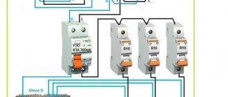
The relay voltage stabilizer consists of the following main components:
- power autotransformer - the basis of the stabilizer, performs voltage correction;
- electronic control circuit – measures the parameters of the supply network and the device itself, controls the operation of power relays;
- power relay block - switches transformer turns in such a way as to ensure rated output voltage parameters;
- monitoring tools – LED indicators, LCD display, popular interfaces for organizing remote control and monitoring.
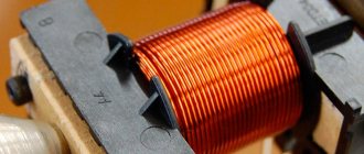
Autotransformer
is a type of voltage transformer with electrically connected primary and secondary windings. The secondary winding has several taps from the coil - terminals, the voltage at which will be different at the same value of the primary voltage. The voltage difference at the terminals of the coil sections is determined by the corresponding transformation ratio of the device, which directly depends on the number of winding turns involved in the transformation.
The operation of a relay stabilizer can be generally described as follows:
- The input voltage passes through a noise suppression filter and is measured by an electronic circuit. Then the mains voltage readings are compared with the nominal value that should be at the output.
- If there is an unacceptable deviation of the voltage in the network from the nominal value, the electronic circuit generates a signal to turn on certain power relays, the switching of which will ensure the required transformation ratio. Due to this, a voltage value will be generated at the output that is as close as possible to the nominal one.
- The electronic circuit can stop the operation of the stabilizer if short circuits, current overloads, long pulses or a discrepancy between the actual voltage in the network and the operating range of the input voltage of the stabilizer occur.
Pulse current stabilizer
A current stabilizer based on a pulse converter is very similar in design to a voltage stabilizer based on a pulse converter, but it controls not the voltage across the load, but the current through the load. When the current in the load decreases, it pumps up the power, and when it increases, it reduces it. The most common circuits of pulse converters include a reactive element - a choke, which, using a switch (switch), is pumped with portions of energy from the input circuit (from the input capacitance) and, in turn, transfers it to the load. In addition to the obvious advantage of energy saving, pulse converters have a number of disadvantages that have to be overcome with various circuitry and design solutions:
- The switching converter produces electrical and electromagnetic interference
- Typically has a complex structure
- Does not have absolute efficiency, that is, it wastes energy for its own work and heats up
- It most often has a higher cost compared, for example, with transformer plus linear devices
Since energy savings are critical in many applications, component designers and circuit designers strive to reduce the impact of these disadvantages, and often succeed in doing so.
Pulse converter circuits
Since the current stabilizer is based on a pulse converter, let's consider the basic circuits of pulse converters. Each pulse converter has a key, an element that can only be in two states - on and off. When turned off, the key does not conduct current and, accordingly, no power is released on it. When turned on, the switch conducts current, but has a very low resistance (ideally equal to zero), accordingly, power is released on it, close to zero. Thus, the switch can transfer portions of energy from the input circuit to the output circuit with virtually no power loss. However, instead of a stable current, which can be obtained from a linear power supply, the output of such a switch will be a pulse voltage and current. In order to get stable voltage and current again, you can install a filter.
Using a conventional RC filter, you can get the result, however, the efficiency of such a converter will not be better than a linear one, since all the excess power will be released at the active resistance of the resistor. But if you use a filter instead of an RC - LC filter (circuit “b”), then, thanks to the “specific” properties of inductance, power losses can be avoided. Inductance has a useful reactive property - the current through it increases gradually, the electrical energy supplied to it is converted into magnetic energy and accumulates in the core. After the switch is turned off, the current in the inductance does not disappear, the voltage across the inductance changes polarity and continues to charge the output capacitor, the inductance becomes a source of current through the bypass diode D. This inductance, designed to transmit power, is called a choke. The current in the inductor of a properly operating device is constantly present - the so-called continuous mode or continuous current mode (in Western literature this mode is called Constant Current Mode - CCM). When the load current decreases, the voltage on such a converter increases, the energy accumulated in the inductor decreases and the device can go into discontinuous operating mode when the current in the inductor becomes intermittent. This mode of operation sharply increases the level of interference generated by the device. Some converters operate in border mode, when the current through the inductor approaches zero (in Western literature this mode is called Border Current Mode - BCM). In any case, a significant direct current flows through the inductor, which leads to magnetization of the core, and therefore the inductor is made of a special design - with a break or using special magnetic materials.
A stabilizer based on a pulse converter has a device that regulates the operation of the key depending on the load. The voltage stabilizer registers the voltage across the load and changes the operation of the switch (circuit “a”). The current stabilizer measures the current through the load, for example, using a small measuring resistance Ri (scheme “b”) connected in series with the load.
The converter switch, depending on the regulator signal, is switched on with different duty cycle. There are two common ways to control a key - pulse width modulation (PWM) and current mode. In PWM mode, the error signal controls the duration of the pulses while maintaining the repetition rate. In current mode, the peak current in the inductor is measured and the interval between pulses is changed.
Modern switching converters usually use a MOSFET transistor as a switch.
Buck converter
The version of the converter discussed above is called a step-down converter, since the voltage at the load is always lower than the voltage of the power source.
Since the inductor constantly flows unidirectional current, the requirements for the output capacitor can be reduced, the inductor with the output capacitor acts as an effective LC filter. In some current stabilizer circuits, for example for LEDs, there may be no output capacitor at all. In Western literature, a buck converter is called a Buck converter.
Boost converter
The switching regulator circuit below also works on the basis of a choke, but the choke is always connected to the output of the power supply. When the switch is open, power flows through the inductor and diode to the load. When the switch closes, the inductor accumulates energy; when the switch opens, the EMF arising at its terminals is added to the EMF of the power source and the voltage across the load increases.
Unlike the previous circuit, the output capacitor is charged by an intermittent current, hence the output capacitor must be large and an additional filter may be needed. In Western literature, a buck-boost converter is called a Boost converter.
Inverting converter
Another pulse converter circuit works similarly - when the switch is closed, the inductor accumulates energy; when the switch opens, the EMF arising at its terminals will have the opposite sign and a negative voltage will appear on the load.
As in the previous circuit, the output capacitor is charged by an intermittent current, therefore the output capacitor must be large and an additional filter may be needed. In Western literature, an inverting converter is called a Buck-Boost converter.
Forward and flyback converters
Most often, power supplies are manufactured according to a scheme that uses a transformer. The transformer provides galvanic isolation of the secondary circuit from the power source; in addition, the efficiency of a power supply based on such circuits can reach 98% or more. A forward converter (circuit “a”) transfers energy from the source to the load at the moment the switch is turned on. In fact, it is a modified step-down converter. The flyback converter (circuit “b”) transfers energy from the source to the load during the off state.
In a forward converter, the transformer operates normally and the energy is stored in the inductor. In fact, it is a pulse generator with an LC filter at the output. A flyback converter stores energy in a transformer. That is, the transformer combines the properties of a transformer and a choke, which creates certain difficulties when choosing its design.
In Western literature, a forward converter is called a Forward converter. Flyback converter.
Using a pulse converter as a current stabilizer
Most switching power supplies are produced with output voltage stabilization. Typical circuits of such power supplies, especially powerful ones, in addition to output voltage feedback, have a current control circuit for a key element, for example a low-resistance resistor. This control allows you to ensure the operating mode of the throttle. The simplest current stabilizers use this control element to stabilize the output current. Thus, the current stabilizer turns out to be even simpler than the voltage stabilizer.
Let's consider the circuit of a pulse current stabilizer for an LED based on the NCL30100 chip from the well-known manufacturer of electronic components On Semiconductor:
The buck converter circuit operates in continuous current mode with an external switch. The circuit was chosen from many others because it shows how simple and effective a switching current regulator circuit with a foreign switch can be. In the above circuit, the control chip IC1 controls the operation of the MOSFET switch Q1. Since the converter operates in continuous current mode, it is not necessary to install an output capacitor. In many circuits, a current sensor is installed in the switch source circuit, however, this reduces the turn-on speed of the transistor. In the above circuit, the current sensor R4 is installed in the primary power circuit, resulting in a simple and effective circuit. The key operates at a frequency of 700 kHz, which allows you to install a compact choke. With an output power of 7 Watts, an input voltage of 12 Volts when operating at 700 mA (3 LEDs), the efficiency of the device is more than 95%. The circuit operates stably up to 15 watts of output power without the use of additional heat removal measures.
An even simpler circuit is obtained using key stabilizer chips with a built-in key. For example, a diagram of a key LED current stabilizer based on the CAV4201/CAT4201 chip:
To operate a device with a power of up to 7 Watts, only 8 components are required, including the chip itself. The switching regulator operates in the border current mode and requires a small output ceramic capacitor to operate. Resistor R3 is necessary when powered at 24 Volts or higher to reduce the rate of rise of the input voltage, although this somewhat reduces the efficiency of the device. The operating frequency exceeds 200 kHz and varies depending on the load and input voltage. This is due to the regulation method - monitoring the peak inductor current. When the current reaches its maximum value, the switch opens; when the current drops to zero, it turns on. The efficiency of the device reaches 94%.
Back to article catalog >>>
Advantages and disadvantages of a relay voltage stabilizer
Due to its simple design, the relay stabilizer is compact and can be operated without special maintenance. Such a device does not make much noise during operation, with the exception of clicks at the moment of operation. As a rule, stabilizers of this type are unpretentious and remain operational over a wide temperature range. The risk of overheating during operation is minimized.
However, a number of disadvantages are also associated with the design features of the relay stabilizer. Since voltage regulation occurs due to the mechanical movement of the relay, the device does not operate instantly. The reaction time to a sudden voltage surge can be about 10-20 ms. It would seem not much, but for complex modern equipment, for example, computer or heating equipment, this may be enough to cause failures.
If lighting devices are connected through the stabilizer, the moment of operation can be seen with the naked eye: the light may blink at the moment the relay switches. In addition, during long-term operation of the stabilizer, the relays may turn out to be its weak point: with frequent operations, they quickly wear out, especially for stabilizers of cheap models.
| Advantages | Flaws |
|
|
Areas of application of relay voltage stabilizers
The scope of application of relay stabilizers is determined by their technical features. They are often chosen as an inexpensive way to protect household appliances from surges in an apartment or country house. They attract the attention of many consumers due to their compactness and low price.
However, the possibilities of using relay stabilizers are quite limited by their disadvantages: modern electronic devices (computers, audio equipment, electronically controlled boilers, security systems) place higher demands on the quality of the input voltage than stabilizers of this type can provide. In particular, they cannot be used for devices that may fail if the stabilizer operates with a delay.
Examples of such loads are heating systems. In addition, the clicks that the relay stabilizer makes when activated may also be undesirable, especially for expensive audio equipment.
Criteria for choosing a relay stabilizer
If you decide to buy a relay stabilizer, then in order to choose the right model, you must be guided by the following criteria:
- device output power;
- speed and accuracy of output voltage correction;
- operating voltage range;
- overload capacity;
- noisy operation;
- permissible operating temperature;
- installation method.
Let's look at some of these criteria in more detail.
| Criterion | Description |
| output power | It is recommended to select the device power taking into account a reserve of 20-30% of the total load power consumption. If there is a load with high starting currents (for example, electrical appliances with electric motors), it is advisable to increase the power reserve. |
| Operating voltage range | Modern relay stabilizers work quite well in networks with large voltage drops. However, if there are frequent significant fluctuations, it is better to avoid devices of this type. The frequency of operation of power relays reduces their service life and, of course, does not increase the service life of the stabilizers themselves. |
| Working temperature | Devices of this type, as a rule, have a wide operating temperature range; however, when installing the stabilizer in an unheated room, you should make sure that the permissible temperature indicators of the selected model correspond to the actual operating conditions. |
| Stabilization accuracy | Considering the stepwise voltage correction, it is recommended to select devices with a large number of power relays. A larger number of control stages ensures better accuracy of its operation. |
Comparison of relay and electronic stabilizers
Electronic and relay devices are characterized by stepwise regulation of the output voltage. The discreteness of voltage correction in stabilizers depends on the number of control stages - these are semiconductor switches in electronic or electromechanical relays in relay devices.
Electronic devices are best used when high performance is required. Relay analogues are significantly inferior in this indicator - the switching speed of electromechanical relays is much lower than that of electronic power switches. In addition, the latter operate completely silently, unlike conventional relays, which makes them much more suitable for installation in residential premises.
The greater operational reliability and long service life of electronic stabilizers is due to the complete absence of moving mechanical parts in the design. The relay mechanics are subject to rapid wear, which is especially evident when operating in networks with extremely unstable mains voltage.
Electronic devices are less resistant to overloads, which can cause overheating and failure of expensive power switches. In addition, electronic stabilizers themselves can introduce distortions into the output signal shape.
The cost of electronic stabilizers is much higher than that of relay ones: the latter are currently much cheaper, which makes them much more preferable for organizing budget load protection that is undemanding in terms of power supply quality.
| Characteristic | Relay stabilizer | Electronic stabilizer |
| Switching transformer windings | Electromechanical relays | Semiconductor switches |
| Voltage regulation type | Discrete | Discrete |
| Performance | The indicators are worse, the response is slower (10-20 ms), since the switching speed of electromechanical relays is lower than that of electronic keys | Better performance (5-10 ms), faster response to changes in voltage parameters |
| Stabilization accuracy | Low (5-10%) | High (can reach 3%) |
| Noise level | They make clicking sounds when the relay is activated | They work silently |
| Reliability and long service life | Performance is worse due to rapid wear of switching relays | The performance is better due to the complete absence of moving mechanical parts in the design |
| Overload resistance | Better performance, high overload resistance | Indicators are worse, weak overload capacity due to the high risk of failure of expensive power switches due to overheating |
| Adding Distortion to the Output Signal | They don't contribute | May contribute |
| Price | Low cost | High price |
Transistor voltage stabilizer
- Stabilizer on one zener diode
- Stabilizer on one transistor
- Transistor stabilizer with short circuit protection
- Stabilizer with adjustable output voltage
Stabilizer on one zener diode
To smooth out voltage ripples and constant current at the output of the power supply, stabilizers are used.
As a rule, the stabilizer is based on a zener diode. Zener diode is a semiconductor device with voltage stabilization properties. Unlike a conventional diode, it operates in reverse polarity (plus is supplied to the cathode), in avalanche breakdown mode. Due to this property of the zener diode, the voltage on it, and therefore on the load, practically does not change. The figure below shows a diagram of a simple stabilizer. This stabilizer is suitable for powering low-power devices.
The principle of operation of the stabilizer on a zener diode
A capacitor is needed to smooth out voltage ripples; it is called a filter. A resistor is needed to smooth out current ripples and is called a damping resistor. The zener diode stabilizes the voltage across the load. For normal operation of this circuit, the supply voltage must be greater than 40...50%. The zener diode should be selected for the voltage and current we need.
Stabilizer on one transistor
To power a higher power load, a transistor is added to the circuit. An example circuit is shown below.
The principle of operation of a stabilizer on a single transistor
The chain of R1 and VT1 is already familiar to us from the previous circuit; this is the simplest stabilizer; it sets a stabilized voltage based on transistor VT2. The transistor, in turn, performs the function of a current amplifier and is a control element in this circuit. For example, as the input voltage increases, the output voltage will tend to increase. This leads to a decrease in the voltage at the emitter junction of transistor VT2, which leads to its closure. In this case, the voltage drop in the emitter-collector section increases so much that the voltage on the zener diode decreases to the original level. When the voltage drops, the stabilizer reacts in the reverse order.
Transistor stabilizer with short circuit protection
In the practice of a radio amateur, mistakes occur and a short circuit occurs. To reduce the consequences of a short circuit, consider a stabilizer circuit for two fixed voltages and with short circuit protection.
As you can see, transistor V4, diodes V6 and V7 have been added to this circuit, and a parametric stabilizer consisting of resistor R1, diodes V2, V3 is equipped with switch S2.
Operating principle of stabilizer protection
This circuit is designed for a short-circuit response current of 250...300 mA; as long as it is not exceeded, the current will pass through a voltage divider consisting of diode V7 and resistor R3. By selecting this resistor, you can adjust the protection threshold. Diode V6 will be closed and will not have any effect on the work. When the protection is triggered, diode V7 will close, and diode V6 will open and bypass the zener diode connections, while transistors V4 and V5 will close. The load current will drop to 20...30 mA. Transistor V5 should be installed on the heat sink.
Stabilizer with adjustable output voltage
When repairing or adjusting electronic devices, it is necessary to have a power supply with an adjustable output voltage. A schematic diagram of voltage-regulated stabilizers is presented below.
The principle of operation of a stabilizer with voltage regulation
A parametric stabilizer consisting of R2 and V2 stabilizes the voltage across the variable resistor R3. The voltage from this resistor is supplied to the control transistor. This transistor is connected according to the emitter follower circuit, the load of which is resistor R4. The voltage from resistor R4 is supplied to the control transistor V4, the load of which is already our powered device. Voltage regulation is carried out by variable resistor R3; if the resistor slider is in the minimum position according to the circuit, then the voltage to open transistors V3 and V4 is not enough and the output will have a minimum voltage. When the engine rotates, the transistors begin to open, which increases the voltage across the load. As the load current increases, the voltage drop across resistor R1 and lamp H1 begins to light up; at a current of 250 mA, a dim glow is observed, and at a current of 500 mA and above, a bright glow is observed. Transistor V4 should be installed on the heat sink. With an increased load of more than 500 mA, you should turn off the power supply as quickly as possible, since under prolonged maximum load the diodes in the rectifier bridge and transistor V4 fail.
These circuits, when assembled correctly, do not require adjustment. They can also be upgraded to higher currents and voltages. By selecting radioelements with the parameters we need.
That's all. If you have comments or suggestions regarding this article, please write to the site administrator.
Good luck!
Inverter stabilizer as an alternative to relay ones
If you want to reliably protect the electronic devices you use in your apartment or country house, you should consider purchasing more modern models of stabilizers - inverter ones.
The operating principle of these devices is based on modern technologies, which have eliminated all the shortcomings inherent in previous generations of voltage stabilizers: the devices instantly respond to fluctuations in the input voltage and adjust it as accurately as possible.
Inverter stabilizers are compact and do not make noise during operation. Their benefits are noticeable even with long-term use:
- do not have moving elements that could fail due to mechanical damage;
- equipped with automatic protection with recovery from overheating, overloads, network failures and short circuits.
All these features make inverter stabilizers the optimal solution for ensuring high-quality power supply in an apartment or country house.
The higher price than relay stabilizers is justified, because you get a more reliable and high-tech device that will last a long time.
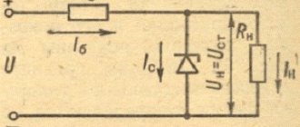
Parametric transistor voltage regulator
So, on the right is a diagram of a simple transistor voltage stabilizer.
Designations:
- Ik - collector current of the transistor
- In — load current
- Ib - transistor base current
- IR - current through the ballast resistor
- Uin - input voltage
- Uout - output voltage (voltage drop across the load)
- Ust - voltage drop across the zener diode
- Ube - voltage drop at the base-emitter pn junction of the transistor
How does such a stabilizer work and how does its operation differ from the operation of a parametric stabilizer using a zener diode? Yes, their work is almost no different - the voltage at the output of the circuit remains stable as a result of the presence of sections on the current-voltage characteristics (zener diode and pn junction of the base-emitter transistor) in which the voltage drop weakly depends on the current. That is, like all parametric stabilizers, stability is achieved by the internal properties of the components.
Indeed, as can be seen from the figure, the voltage drop across the load is equal to the difference in the voltage drops across the zener diode and at the pn junction of the BE transistor. Since the voltage drop across the zener diode weakly depends on the current (in the working section it is equal to the stabilization voltage), the voltage drop across the forward-biased pn junction also weakly depends on the current (for a silicon transistor it can be taken approximately the same as for a conventional silicon diode - approximately 0. 6 Volts), it turns out that the output voltage is also constant.
Now let's add a little math.
Everything is already clear with the load voltage (output voltage): Uout=Ust-Ube
, let's calculate R0 and the area of normal operation of the stabilizer. But first, let’s draw two pictures side by side - a piece of the circuit of our stabilizer and a piece of the simplest parametric stabilizer on a zener diode:
It looks like it, doesn't it? Moreover, the reasoning and the relationships derived from them for calculating R0 and the normal operation area are also very similar.
The equation describing the currents and voltages for the piece of our stabilizer circuit torn out above:
Uin=Ust+IRR0, taking into account that IR=Ist+Ib, we get
Uin=Ust+(Ist+Ib)R0 (1)
For normal operation of the stabilizer (so that the voltage on the zener diode is always in the range from Ust min to Ust max), it is necessary that the current through the zener diode always be in the range from Ist min to Ist max. The minimum current through the zener diode will flow at the minimum input voltage and maximum base current of the transistor. Knowing this, we find the resistance of the ballast resistor:
R0=(Uin min-Ust min)/(Ib max+Ist min) (2)
If we take into account that in our case, when the transistor is connected according to a circuit with a common collector, the base current is related to the emitter current by the ratio Ie = Ib (h21E + 1), the emitter current is equal to the load current (because we have a load connected to the emitter circuit) , and the voltage on the zener diode in operating mode changes slightly (instead of Ust min, let’s just take Ust), then we get that
R0=(Uin min-Ust)/(In max/(h21E+1)+Ist min) (3)
h21E+1 is the current gain for a circuit with a common collector (h21K), but since h21E is usually quite large, the “+1” term is often thrown out and it is assumed that h21K = h21E, then formula (3) becomes a little simpler:
R0=(Uin min-Ust)/(In max/h21E+Ist min)
The maximum current through the zener diode will flow at a minimum transistor base current and a maximum input voltage. Taking this into account and what was said above regarding the minimum current through the zener diode, using equation (1) you can find the area of normal operation of the stabilizer:
Regrouping this expression, we get:
Or, in another way:
If we assume that the minimum and maximum stabilization voltage (Ust min and Ust max) differ slightly (the first term on the right side can be considered equal to zero), and also that Iн=Iе=Iбh21Э (“+1” - we’ll throw it out), then the equation describing the area of normal operation of the stabilizer will take the following form:
(4)
This formula clearly shows the advantage of such a transistor stabilizer over a parametric stabilizer based on a zener diode - with all other parameters being equal, the output current of a transistor stabilizer can vary within a wider range.
For example, let’s again take the KS147A zener diode (Ist = 3..53mA), and let’s estimate what maximum current we can expect when the voltage is reduced from 6..10V to 5V, provided that the output current can vary from zero to Imax. Let's take the transistor KT815A (h21E=40). Having solved the system of equations (3), (4) together, we obtain R0 of about 110 Ohms and a maximum current of about 550 mA.
However, it is worth noting that the instability of the output voltage in this case will be even worse, since now the instability of the voltage drop at the pn junction of the transistor will be added to the instability of the voltage on the zener diode. Plus, we have not yet taken into account that the output voltage will be less than on a zener diode by the amount of voltage drop across the pn junction, so for good measure we would have to take a zener diode not at 4.7 V, but at 5.1 or even 5.6 Volt (I specifically took as an example the same zener diode as in the article about a parametric stabilizer on a zener diode, so that it could be more clearly seen how the load current would differ with the same zener diode).
Actually, the methods of dealing with instability here are completely similar - you need to somehow reduce the instability of the voltage on the zener diode. To do this, you can, as last time, take a narrower working section of the I-V characteristic of the zener diode. This, naturally, will also lead to a narrowing of the area of normal operation (because the range of change in the operating current of the zener diode will decrease), but in this case, when the area of normal operation is already wider than that of a parametric stabilizer on a zener diode (about h21E times), we may well afford to give up part of the output current range and/or part of the input voltage range in order to increase the stability of the output voltage.
You can further increase the area of normal operation if you use two transistors connected according to a Darlington or Szyklai circuit (figure on the left). In this case, h21E will be much larger.
Well, the most squeaking thing is to make a compensation voltage stabilizer on an operational amplifier, since the gain of the op-amp is not just greater, but significantly, much, many, many times greater than that of any transistor (accordingly, we will be able to change the current through an even narrower range Zener diode, we get an even smaller change in voltage across it and, as a result, an even more stable output voltage).
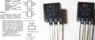
There is another option - instead of a regular zener diode, you can take an integral zener diode, for example, TL431. In this case, in addition to significantly less instability, we also get the ability to regulate the output voltage.
For starters, I’ll say that with a slight movement of the hand, such a voltage stabilizer can be turned into a current stabilizer (you just need to stabilize the voltage not at the load, but at a special current-measuring resistor).