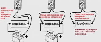
Verification steps
Diodes operate at low DC voltage.
It is generated by blocks that are difficult to connect to. But part of the LED design is a semiconductor junction, due to which current is passed in a given direction. If there is enough current, the light bulb lights up. Checking diodes with a multimeter
Using a multimeter, it is easy to determine the health of the element. To do this, set the device to dialing mode, after which:
- The probes are thrown onto the area of the semiconductor that needs to be checked.
- The red probe with a positive charge is connected to the LED anode.
- A black probe with a negative charge is thrown onto the cathode.
- The device screen should display an indicator of the voltage drop after the pn transition.
- The polarity of the connection changes. If there is no voltage drop, the diode is operational.
If the multimeter does not have a “Ring” mode, set it to 1 Ohm with the switch.
Infrared
As we acquire consumer electronic devices, each of us gradually becomes the owner of a whole battery of remote controls. As long as the equipment obediently responds to your commands, there is nothing to worry about.
But such a situation is quite likely,
when desperate attempts to change the channel or turn down the brightness of the chandelier do not lead to any result.
In such cases, first check the status of the infrared LED, through which the remote control transmits your requirements to the main device.
There are several ways to check the IR LED in a remote control or other device. Let's start with the simplest:
Direct the diode radiation into the lens of a digital camera. Not only a camera will do, but also a phone, laptop, video recorder, web camera, etc. IR radiation is absolutely invisible to the human eye, but electronic “eyes” register it very well. If the LED is performing its functions properly, purple flashes will be observed on the matrix.
If you don’t have a gadget that can remove it, the suspected LED can be dismantled by replacing it with a super-bright or SMD-type LED. Just make sure that the operating voltage of both elements is the same.
If the test LED emits visible light when pressing buttons on the remote control (most likely, it will be dim), then the IR LED has already served its purpose.
A more complicated method, but it does not require a camera or soldering. You can use an infrared photodiode. When infrared radiation hits the sensor of this element, a potential difference is formed at its terminals.
To test any IR LED, its radiation must be directed to the sensitive area of a photodiode previously connected to the open input of the oscilloscope.
If pulse curves appear on the device screen, the LED under test is in working condition. If you observe complete calm, then it’s time to buy a new IR LED.
Testing LEDs in dialing mode
A multimeter is a universal meter that allows you to check the serviceability of almost any electrical device or element. To check a light-emitting diode using a tester, it is necessary that the device can switch to diode testing mode, which is most often called continuity testing.
Checking the serviceability of the LED with a multimeter is carried out in the following order:
- Set the tester switch to diode test mode.
- Connect the multimeter probes to the contacts of the element being tested.
- When connecting an LED, you should take into account the polarity of its terminals (the black probe of the measuring device is connected to the cathode, and the red one to the anode). However, if the exact location of the poles is unknown, then there is nothing wrong with an incorrect connection, and the LED will not fail in this case.
If the probes are connected to the contacts incorrectly, then the initial readings on the tester display will not change. If the polarity is not reversed, the working diode will light up.
- The continuity current is small and is not enough for the LED to work at full capacity. Therefore, you can see the glow of the element by slightly darkening the room.
- If there is no way to dim the lighting, you need to look at the readings of the multimeter. When checking the working diode, the values on the device display will differ from one.
Visually checking the LEDs in the video:
Using this method, you can check even a powerful diode for functionality. The disadvantage of this method is that it will not be possible to diagnose the elements without removing them from the circuit. To test LEDs in a circuit, adapters must be connected to the probes.
Sometimes the serviceability of a part is checked by measuring the resistance, but this method is not widely used because to use it, you need to know the technical parameters of the diode.
Checking LEDs without desoldering
To connect the probes of the measuring device to the PNP block, small metal tips should be soldered to them, for which you can use simple paper clips.
To more reliably insulate cables with soldered lugs, insert a PCB gasket between them and wrap the structure with electrical tape.
Through these simple manipulations we will get a reliable and at the same time simple adapter with which we can connect the multimeter probes to the contacts of the light-emitting diode.
Then the probes are connected to the contacts of the LED element, and there is no need to unsolder the latter from the general circuit. Further verification is carried out in the same order as described above.
Let's give a clear example of checking the serviceability of an LED without removing it from the circuit.
Continuity of individual LEDs
This type of test is one of the simplest and is done using a multimeter. A standard LED has two long contacts - an anode and a cathode. The cathode leg is slightly longer, and when viewed against the light, its electrode inside the housing is larger. In order to ring the LED, you must perform the following steps:
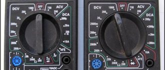
- move the switch to the Hfe position (this is the transistor test mode);
- find the connector on the panel marked PNP and NPN;
- The anode is inserted into slot C of the PNP zone, and the cathode is inserted into slot E of the NPN zone.
These pins are the positive and negative electrodes and cause the LED to glow. If this does not happen, then either the polarity is reversed (the diode leads must be swapped), or the element is faulty. Before checking an LED with a multimeter, it is recommended to determine where its anode and cathode are.
Since multimeters have different designs and characteristics, there are several types of sockets for testing transistors.
Despite the differences, they all have the required slots.
How to determine LED voltage with a multimeter
In this article we will explain in detail how to determine the voltage of an LED with a multimeter.
Soldering iron YIHUA 8858
Updated version, power: 600 W, air flow: 240 l/h...
More details
All LEDs have a very important characteristic - operating voltage (drop voltage). The amount of operating voltage depends on the materials from which they are made. Based on operating voltage, all LEDs can be divided into 2 groups:
- LEDs with voltage from 3 V to 3.8 V (blue, white and some types blue-green)
- 1.8V to 2.1V LEDs (red, yellow, orange and most green)
Due to the fact that manufacturers often create new LED models, we recommend that you first determine the voltage of the LEDs before using them in your designs.
It is very easy to determine this voltage. To do this, we only need a power supply with an output voltage of 9 to 16 V, a multimeter and a 1 kOhm (1000 Ohm) resistor. This resistance value guarantees the optimal current for our LED, not too high and not too low.
Below are the steps required to measure the operating voltage of an LED.
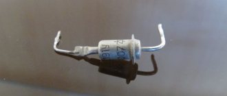
STEP 1: Determine the polarity of the leads of our LED.
To determine the polarity of our LED, there are two elements in its body that we can evaluate.
The first is the length of the leads. As you can see in the figure, the shortest pin is the negative pin.
The second is that the element is located around the circumference of the LED. There is a bevel on the body - this is the negative terminal.
The described detection method works for all 3 mm and 5 mm LEDs.
A third method can also be used, which is to look inside the LED, the triangular pennant-shaped segment is the negative terminal, and the other, without any special shape, is the positive one. Of course, this method is not safe, since there are several types of LEDs where the arrangement is the opposite.
STEP 2: Connect our LED
Once we have determined the polarity of our LED, we connect one of the leads of the 1k ohm (1000 ohm) resistor in series with the positive lead of the LED as shown in the figure.
We then connect the other terminal of the resistor to the positive side of the power supply. Finally, we connect the free lead of the LED to the negative of the power supply. The LED should light up.
STEP 3: Prepare our multimeter
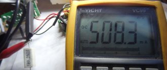
Now we prepare our multimeter to take the measurement. Move the tester selector to the DC voltage measurement position with a scale of up to 20 V. If our multimeter does not have this voltage scale, then we can select 30 V or 50 V.
We connect the negative probe (black) to the input labeled “COM”, while the positive (red) probe is connected to the V-mA-ῼ input. You should see the value “0.00” on the display
STEP 4: Determine LED Voltage
We apply the positive probe (red) to the positive terminal of the LED, while the negative (black) probe of the multimeter is applied to the negative terminal. On the multimeter display we should see the operating voltage of the LED.
We can write down this value as it will be useful in calculating the LED resistance value. To calculate the resistance of LEDs, use an online calculator.
www.inventable.eu
Transistor tester / ESR meter / generator
Multifunctional device for testing transistors, diodes, thyristors...
More details
Checking the diode on the board
It is often necessary to test an LED without desoldering it from the circuit. In such cases, the technique remains the same, but the technology changes. Since it is impossible to insert the LED legs into the multimeter slots, probes are used. The hole sizes of the slots for testing transistors are too small, so the probes will have to be modified. Thin contacts should be attached to the free ends, which can be used as:
- sewing needles;
- straightened paper clips;
- pieces of thin wire, etc.
Some craftsmen use a small plate of getinax or textolite foil on both sides, to which pieces of wire are soldered, forming something like a fork. It is inserted into the required slots of the multimeter, after which you can use standard (not modified) probes.
Attention! Testing LEDs in a flashlight is done in a similar way, but the design of the device most often does not allow access to the board. You have to carefully solder it from the battery pack, remove it from the case, after which you can check the elements using multimeter probes in the usual way.
Checking LED lamps
For the convenience of consumers, the production of lamps based on LEDs has now been launched, which have a geometric configuration similar to the already familiar incandescent lamps. This makes it possible to install LED lamps in ordinary lamps powered by a 220 V network.
A special current converter – driver – is built into the design of such a lamp. This device is assembled from parts that have parameters that differ in each individual model. This circumstance makes it impossible to use this type of diagnostics, such as checking an LED lamp with a multimeter.
The LED lamp is tested using a special tester. It is a device, inside of which a circuit is assembled that allows you to check the performance of lamps of various types. For this purpose, the body has several connectors for the most commonly used lamp bases. The test result is displayed in the form of a sound signal.
Checking the LED spotlight
First you need to determine what type of LED is installed in the spotlight. There may be two options:
- board with small SMDs;
- one large yellow element.
The LED is checked for serviceability based on its type. For a board with SMD, the already discussed method of testing with a multimeter is used. This method is not suitable for large yellow samples, since their supply voltage ranges from 10 to 30 V, which is too high for a multimeter. There is only one way to check such a device yourself - using a known working, serviceable driver that matches the operating parameters of the LED being tested.
Checking the LED strip
An LED strip is a light source consisting of many elements. They are spaced evenly along the length of the tape and grouped in threes. This allows you to cut the LED strip into pieces of almost any length without compromising its performance properties. The main thing is that the cut does not fall in the middle of a group of three elements.
Testing the tape involves applying current to the power contacts. If the tape lights up, it is working. If the entire strip does not light up, the fault must be looked for in the supply wires. To do this, you can ring them with a tester. You can measure the resistance with a multimeter to check the integrity of the wires.
If, when the power is turned on, individual groups in the strip do not light up, the problem is not in the supply wires, but in a specific segment with LEDs. In this case, they are checked using the method described above, and the resistor (there is only one for the entire group) is also checked for compliance with the specified resistance value.
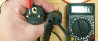
Checking the power supply
Checking is greatly facilitated if there is a source of appropriate voltage nearby.
To understand whether the LED strip is working or not, it is enough to apply the required 12-24-36V to it. You don't even need to solder the wires.
Connect two conductors to the output terminals of the block, and simply touch their tips to the outer copper pads at the beginning of the tape. If the glow is uniform and not dim, then everything is fine.
But when nothing lights up, you need to look for the reason. The most important assistant in this is a multimeter.
First of all, check whether the required voltage is coming out of the power supply? Maybe it's all about him.
You need to check between contacts “+V” and “-V”.
Or “+V” and “COM”.
If the voltage is normal (+ - 10%), then look further along the chain.
If you don’t have a multimeter, you can check using indirect signs. However, you should not rely on them:
- after applying 220V voltage, the green LED on the unit should light up
- if you listen, any power source in working condition should emit a faint characteristic noise
When this is not the case, then we can assume that the unit is faulty. After which, you still have to look for a device to measure the output voltage and confirm your guesses.
Diagnostics of the LED in the flashlight
An LED flashlight, battery-powered or other types, is a fairly reliable device, but it is not immune to breakdowns. If, even after installing new batteries, the glow remains weak or completely absent, you need to check the functionality of the LEDs and their drivers.
Before diagnosing a flashlight, it would be a good idea to check the batteries (even if they have just been unpacked) on some known good device. This advice may seem trivial to some, but quite often, as practice has shown, the cause of “showdowns” with household electronics is defective batteries, which is the last thing the home craftsman realizes.
Checking the flashlight is carried out in the following sequence:
- Unscrew the cap or conical part at the front of the housing.
- We remove the LED module.
- There are two contact pads on the LED board, to which the red and black wires are connected. The red wire corresponds to the positive polarity (marked “+” on the board), and the black wire corresponds to the negative polarity (marked “-”). In accordance with the polarity, a voltage of 3–4 V (no more than 4.2 V!) should be briefly applied to the contacts. If the brightness of the LED has not changed, then it needs to be replaced. Otherwise (the LED lights up properly), the driver must be replaced.
- Replacing an LED is only possible if its board is attached to the LED module capsule with screws. If the board is mounted on hot-melt adhesive, replacement will be impractical; in this case, the entire module is replaced.
This is what the LED module looks like in a Magicshine flashlight
. After unscrewing the board, you should unsolder the LED, and then install a new one.
In flashlights, LEDs are installed on aluminum radiators. To ensure effective heat dissipation, a fresh coat of special heat-conducting paste, also called thermal paste, should be applied to the heatsink before installing a new LED. The old dried layer, even if quite thick, cannot be reused and must be removed.
The test of a separate LED and the simplicity of the tester’s design are clearly demonstrated in the following video from the largest supplier of electrical equipment in Russia.
Often, when one or another electronic device breaks down, we without hesitation take the victim to repair, where we are presented with a hefty bill. Meanwhile, the cause of the accident may simply be a failure of the LED, which can easily be replaced on your own. Thus, the ability to check the performance of these elements, which are used quite widely today, will save money and reduce repair time to a minimum.
How to check the LED?
p, blockquote 2,0,0,0,0 –>
Use a coin cell battery to test the LED without burning it out. A rechargeable battery is the safest option because they will not supply enough current to damage the LED. Testing with any other type of battery may cause the LED to burn out. Buy these batteries at pharmacies, department stores, convenience stores, or online.
p, blockquote 3,0,0,0,0 –>
p, blockquote 4,0,1,0,0 –>
- Use either CR2032 or CR2025 cell batteries.
- Purchase a matching battery holder with cells. Buy one that is made to hold the type of coin cell battery (such as CR2025) you will be testing with. You can find them online or at some hardware or electronics stores. Make sure the holder has red and black wires to test the LED indicators. Coin battery holders are commonly used to add battery power to small projects such as LED jewelry or clothing.
- Some lead battery holders come with a small connector on the end, holding the tips of the two leads.
- If your battery holder has a connector, test your LED by inserting the anode and cathode into the small holes that line up with the red and black wires.
- If your light doesn't light up, try checking other LED lights right after it. If they light up, you can be sure that the first LED is not working.
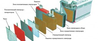
Checking the LED Bridge
Checking the diode bridge
The diode bridge is an assembly of 4 elements. They are connected so that AC voltage is supplied to two of the 4 terminals, turns into DC voltage and is removed from the other 2 terminals. Zener diodes equalize voltage within a narrow range.
You can ring the LED bridge like this:
- Find which pin to connect the multimeter to by making a conditional numbering.
- Ring the first diode by placing probes on pins 1 and 2.
- Test the second LED by connecting probes to pins 2 and 3.
- Measure the parameters of the third diode by connecting probes to pins 1 and 4.
- Determine the serviceability of the fourth element by placing probes on pins 4 and 3.
- View the readings on the scoreboard.
Voltage stability is checked in the maximum range mode - 220 V. It is increased gradually and stopped supplying until current flows through the circuit.
You will need to place the black probe on the anode, the red one on the cathode, and then connect the anode to the current limiting resistor, and the cathode to the power source.
Checking with improvised materials
To detect faults in LEDs, an LED tester is used, made from improvised means - several AA batteries connected in parallel, or a powerful “Krona”.
The tester is also assembled from an unnecessary charger for a phone or other electrical device. Cut the connector at the end of the cord and strip the wires. Connect red (plus) to the anode, and black (minus) to the cathode. If there is enough voltage, the LED will light up.
Flashlight chargers are useful if a light bulb or strip with more powerful LEDs is faulty.
Other verification methods
In addition to a multimeter, you can check LEDs using a battery.
The best option is a CR2032 battery, which is used in the computer motherboard. Its voltage is 3 V, which is enough for most LEDs. It is possible to use 4.5 or 9V batteries, but in such cases you will need to connect a ballast resistor, which gives a voltage drop to safe levels. For Krona you will need 750 Ohms, for 4.5V batteries - 150-200 Ohms.
The LED strip can be checked with a 12 V battery. These are found in remote controls and doorbells. By connecting the contacts of the tape to the corresponding poles of the battery, areas with burnt-out elements are determined. No less problematic elements are the connection areas of individual parts of the LED strip - connectors that oxidize and stop conducting current. Before you start dialing, you need to check their condition - perhaps the problem lies there.
Important! If you need to test a UV LED, you should be careful when connecting it to a power source. Such devices are sensitive to overvoltage and easily fail. The nominal value for which the ultraviolet LED is designed is 3.4-4 V, these figures cannot be exceeded.
Checking the flashlight
A small LED flashlight is not just a children's toy, although some girls and boys sometimes literally annoy their parents by shining it in their eyes. And if the child wants to play doctor and is going to examine your throat, there’s nothing to say. Such a tiny lighting device is very helpful on a dark street or when looking for the necessary little things that have rolled under the sofa or bedside table.
LEDs can burn out at the moment when we are charging a flashlight, and with all the availability and ease of purchasing a new one, it is better to first make sure at home that a breakdown has occurred. To do this, you need to remove the board on which the LEDs are installed and apply the method described in the previous section, using slightly upgraded multimeter probes, the tester itself, or a set of batteries.
Someone will say that flashlights, LED strips and mini-lamps are not so expensive that you have to tinker with them yourself because of one burnt-out element. But try explaining to your son that his favorite flashlight will no longer work. It’s better not to try, but to sit down with him and fix it. It won’t take much time, but there will be so much pleasure that words cannot express it. So don’t be lazy, arm yourself with a multimeter or a “cunning” device made from batteries and everything will be easy and simple.