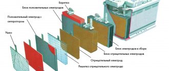
Verification steps
Diodes operate at low DC voltage.
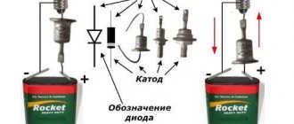
It is generated by blocks that are difficult to connect to. But part of the LED design is a semiconductor junction, due to which current is passed in a given direction. If there is enough current, the light bulb lights up. Checking diodes with a multimeter
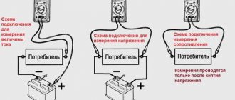
Using a multimeter, it is easy to determine the health of the element. To do this, set the device to dialing mode, after which:
- The probes are thrown onto the area of the semiconductor that needs to be checked.
- The red probe with a positive charge is connected to the LED anode.
- A black probe with a negative charge is thrown onto the cathode.
- The device screen should display an indicator of the voltage drop after the pn transition.
- The polarity of the connection changes. If there is no voltage drop, the diode is operational.
If the multimeter does not have a “Ring” mode, set it to 1 Ohm with the switch.
Checking the LED with a multimeter tester for serviceability
To check for serviceability, no equipment other than a conventional digital multimeter is required. The easiest way is to use probes, which allow you to check elements with any number of leads in any design. After installing the device for ringing, you need to touch the anode with a red probe and the cathode with a black probe. A working diode lights up, and after changing the polarity, the number “1” appears on the screen.
The glow when checking is small, if the lighting is good, it is not visible at all. If the LED element is multi-colored, it is necessary to determine the pinout so that during testing you do not go through the pins at random.
Most multimeters have transistor test jacks that can be used to test diodes. By design, these are 8 holes in the bottom (4 for PNP transistors and 4 for NPN transistors). To test LEDs in PNP, the anode is inserted into socket “E”, the cathode into socket “C”. If the diode is working, it lights up. When tested in NPN, the polarity is reversed.
Important! The disadvantage of this method is that it is impossible to check elements with solder residues without long legs.
To test powerful SMDs you need a driver. The multimeter is connected to it in series, changes in current are visible on the screen. If the element is of low quality, the indicator increases smoothly. The voltage drop is measured by connecting a multimeter in parallel. To determine whether the LED element is suitable for further use, the obtained indicators are compared with the technical documentation data.
If the LED is infrared, if the anode and cathode are positioned correctly, the number 1000 is displayed on the screen; when the polarity is changed, the number 1 is visible.
The main causes of malfunction and failure of LEDs
A feature of LEDs is the reverse voltage, which is only a few volts higher than the drop. The LED fails if even the slightest mistake is made during connection. Super-bright diodes in the backlight burn out during voltage surges. 220 and 12 V lamps are more stable in this regard. Approximately 2% of LED products are supplied with defects; it is advisable to check each one before installation.
Testing LEDs in dialing mode
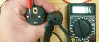
A multimeter is a universal meter that allows you to check the serviceability of almost any electrical device or element. To check a light-emitting diode using a tester, it is necessary that the device can switch to diode testing mode, which is most often called continuity testing.
Checking the serviceability of the LED with a multimeter is carried out in the following order:
- Set the tester switch to diode test mode.
- Connect the multimeter probes to the contacts of the element being tested.
- When connecting an LED, you should take into account the polarity of its terminals (the black probe of the measuring device is connected to the cathode, and the red one to the anode). However, if the exact location of the poles is unknown, then there is nothing wrong with an incorrect connection, and the LED will not fail in this case.
If the probes are connected to the contacts incorrectly, then the initial readings on the tester display will not change. If the polarity is not reversed, the working diode will light up.
- The continuity current is small and is not enough for the LED to work at full capacity. Therefore, you can see the glow of the element by slightly darkening the room.
- If there is no way to dim the lighting, you need to look at the readings of the multimeter. When checking the working diode, the values on the device display will differ from one.
Visually checking the LEDs in the video:
Using this method, you can check even a powerful diode for functionality. The disadvantage of this method is that it will not be possible to diagnose the elements without removing them from the circuit. To test LEDs in a circuit, adapters must be connected to the probes.
Sometimes the serviceability of a part is checked by measuring the resistance, but this method is not widely used because to use it, you need to know the technical parameters of the diode.
DIY LED testing device
Author: serg_svd Published 05/11/2017 Created using KotoEd.
Preface. You may ask: “Why do we need such a tester?” From time to time, a radio amateur has a small problem when installing an LED in a particular structure. Basically, it consists of answering a few simple questions: - what current is needed for the LED and how it will glow at the selected current (especially in devices where power consumption from the power source is critical); — calculation of the quenching resistor in the LED circuit.
A few years ago, having seen a simple tester for LEDs on Aliexpress at a price of 2-3 USD, I wanted to buy it.
But after searching for information about it, the desire to buy disappeared. Essentially it was a box with a bunch of connectors, powered by a 9 V battery. The LEDs were powered from this battery through quenching resistors. Nonsense in general... The next thought was to make the simplest current stabilizer yourself, either on the LM317 or on the 1117 stabilizer and power the LED with a given current, and measure the voltage drop across it using a tester. But finding the idea cumbersome and inconvenient, I abandoned it.
And recently I accidentally came across this article https://robotroom.com/LED-Tester-Pro-1.html. The author of this article followed the same path. Moreover, at first he also just made a current stabilizer board, and measured the current and voltage drop with a tester. But also, finding it inconvenient, he used a microcontroller for measurement instead of a tester. I really liked the idea. But, since the author did not upload the firmware, I had to write it myself. At the same time, I studied the use of an ADC in a microcontroller. In terms of functionality, the resulting tester is 99% similar to the tester presented in the article. I added a short circuit indication mode on the measuring pads for connecting the LED.
The tester can: - measure and display the voltage drop across an LED or pn junction; — measure and display the current flowing through the LED; — calculate the resistance of the quenching resistor in the LED circuit at a given power source voltage (built-in calculator mode); — displays an invitation to connect the LED; — displays a short circuit of the terminals.
I used ATmega8A in a TQFP package as a microcontroller. It was available. In general, I tried to use parts in the device that can be picked out from used motherboards and other computer (and not only) junk. An 8x2 display was also available. I used it without backlight so as not to waste battery power. I thought about food for a long time. The author used a 9 V battery. I don't like them very much. And first of all because of its price, and secondly because of its capacity. After weighing all the pros and cons, I came to the conclusion that lithium power supply should not be fenced off. And even more so, use AA or AAA elements. This tester is really needed infrequently and one battery will last for several years in normal amateur radio practice.
Continuity of individual LEDs
This type of test is one of the simplest and is done using a multimeter. A standard LED has two long contacts - an anode and a cathode. The cathode leg is slightly longer, and when viewed against the light, its electrode inside the housing is larger. In order to ring the LED, you must perform the following steps:
- move the switch to the Hfe position (this is the transistor test mode);
- find the connector on the panel marked PNP and NPN;
- The anode is inserted into slot C of the PNP zone, and the cathode is inserted into slot E of the NPN zone.
These pins are the positive and negative electrodes and cause the LED to glow. If this does not happen, then either the polarity is reversed (the diode leads must be swapped), or the element is faulty. Before checking an LED with a multimeter, it is recommended to determine where its anode and cathode are.
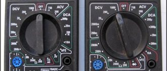
Since multimeters have different designs and characteristics, there are several types of sockets for testing transistors.
Despite the differences, they all have the required slots.
LED Probe | Homemade catalog
Given the ever-growing interest in light-emitting diodes (LEDs). In particular, today LEDs are installed in all lighting fixtures, replacing outdated incandescent lamps and fluorescent tubes. In new lamps, the type of LEDs installed is most often unknown, so it is recommended to have at least some kind of tester to check their serviceability.
It is not always possible to simply check LEDs with a digital multimeter, since you can see a faint glow when the switch is positioned on the continuity or diode resistance only with low-current LEDs, often red or green. But this test option is not suitable for most white, blue, and some yellow light elements, whose operating voltage reaches 3.3 V.
If you are tired of looking through a magnifying glass at the insides of a light-emitting crystal to presumably determine its anode and cathode, or tired of holding the multimeter probes on the short legs of an unruly little element that constantly tries to slip out, then spend just an hour and assemble your own simple LED probe. The LED probe circuit is so simple that it seems to say why I didn’t think of this before!
- The device assembled according to this scheme has the form of an attachment, which is plugged into the measuring sockets of any multimeter you have at home.
- To assemble the device, all you need is:
- Connecting block pulled from an old Krona battery.
- A suitable Krona battery for powering the probe.
- A micro-button without locking; a clock button from a tablet or phone is also suitable.
- Quick-release socket for transistors - socket with a pitch of 2.54 mm, 3 contacts is enough.
- One 1 kOhm resistor, 0.25 W.
- A plastic plate or part of the housing to secure all the parts.
- Four brass screws.
Drill four holes in a plastic plate of suitable size:
- two for securing the connecting block to which the Krona battery will be connected;
- two for installing homemade plugs from brass screws that will fit into the sockets of an existing multimeter at home.
It is recommended to make the pins without thread along the entire length, not as shown in the photo. The M4 thread is only needed to secure the plugs in the plastic case of a homemade LED set-top box.
- To secure the microbutton and the transistor quick-release socket, you need to cut a separate board from fiberglass.
- From the inside of the board, guided by the electrical circuit diagram, we solder a 1 kOhm, 0.25 W resistor and wires to the transistor socket and microbutton.
- We collect everything into a common housing, connect the output wires to the connecting block for supplying power from the Krona battery and to homemade plugs for measuring voltage with a multimeter.
- For clarity and speed of determining the anode and cathode of the elements being tested, we glue in a free space near the connection socket a schematic image of the LED, according to the connected power wires: red “plus” is the anode, black “minus” is the cathode.
- To carry out measurements: we connect a ready-made attachment with a Krona battery to the multimeter, set the measurement limit from 2 to 20 V DC, plug in any LED being tested at random, press the start testing button, and if the LED is connected correctly and is also working, then it will definitely light up.
- With this probe you can find out:
- LED serviceability;
- pinout of its legs;
- supply voltage.
If you are not very interested in the supply voltage of the LED being tested, then you can do without a multimeter at all.
This very simple device provides enough information about any unknown LED. It is so convenient that it will only delight every electronics engineer.
Vitaly Petrovich, Ukraine, Lisichansk.
Source: https://volt-index.ru/podelki-dlya-avto/probnik-svetodiodov.html
Checking the diode on the board
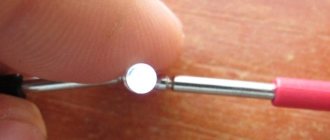
It is often necessary to test an LED without desoldering it from the circuit. In such cases, the technique remains the same, but the technology changes. Since it is impossible to insert the LED legs into the multimeter slots, probes are used. The hole sizes of the slots for testing transistors are too small, so the probes will have to be modified. Thin contacts should be attached to the free ends, which can be used as:
- sewing needles;
- straightened paper clips;
- pieces of thin wire, etc.
Some craftsmen use a small plate of getinax or textolite foil on both sides, to which pieces of wire are soldered, forming something like a fork. It is inserted into the required slots of the multimeter, after which you can use standard (not modified) probes.
Attention! Testing LEDs in a flashlight is done in a similar way, but the design of the device most often does not allow access to the board. You have to carefully solder it from the battery pack, remove it from the case, after which you can check the elements using multimeter probes in the usual way.
A simple LED tester
Recently, homemade and industrial devices with LEDs have become very popular. They are found almost everywhere today. They are also starting to use LEDs instead of old tubular fluorescent lamps, but we can keep silent about incandescent lamps. Due to the fact that there is a huge variety of diodes, to check them it will be useful to have a tester, or make one yourself.
Of course, some LEDs can be checked with a regular multimeter in dial mode. The LED should light up. But if it operates at a higher voltage than the multimeter outputs, the glow will be very weak or not at all. For some white, yellow and blue LEDs, the voltage can reach 3.3V.
First of all, when testing an LED, you need to determine where its cathode is and where its anode is. Of course, this can be determined by examining the insides of the crystal, but this takes time, effort, nerves, and in general this is an unprofessional approach.
Among other things, the manufactured probe will help determine what operating voltage the LED has, and this is a very important parameter. And finally, the device will help you trivially determine the serviceability of the LED.
Device diagram
According to the author, the device circuit is very simple. The homemade product is an attachment that plugs into the socket of a multimeter.
Homemade manufacturing process:
Step one. We prepare the necessary elements
First you need to prepare the contacts that will connect to the multimeter. The photo shows that the pins have threads, but it is best to get rid of them. The thread is needed only to screw the elements using nuts to the plastic body.
To attach the pins, you need to drill fourth holes in the plastic plate. Two are needed to install the connecting block through which the Krona battery is connected. And the second two are needed for mounting the contacts with which the device is connected to the multimeter.
To test the LED, you need to plug it into the connector and connect the Krona battery to the socket. Now the multimeter switches to voltage measurement mode in the range of 2-20V DC. If the diode is working and turned on correctly, it will light up.
As mentioned at the beginning, you can use a multimeter to determine the operating voltage of the LED, but if this is not necessary, a multimeter is not needed at all. That's all, the little helper is ready, now it will be much more pleasant and faster to assemble homemade products with LEDs or repair something.
Source
Checking LED lamps
For the convenience of consumers, the production of lamps based on LEDs has now been launched, which have a geometric configuration similar to the already familiar incandescent lamps. This makes it possible to install LED lamps in ordinary lamps powered by a 220 V network.
A special current converter – driver – is built into the design of such a lamp. This device is assembled from parts that have parameters that differ in each individual model. This circumstance makes it impossible to use this type of diagnostics, such as checking an LED lamp with a multimeter.
The LED lamp is tested using a special tester. It is a device, inside of which a circuit is assembled that allows you to check the performance of lamps of various types. For this purpose, the body has several connectors for the most commonly used lamp bases. The test result is displayed in the form of a sound signal.
Automatic LED tester SID GJ2C
The most common malfunction of LED TVs is the presence of sound but no picture. The reason is the burnout of the LED light bulbs in the backlight. For a technician repairing this equipment, the SID GJ2C device, which automatically selects parameters, saves time on checking. It can also be used to test LED strips and lamps in any luminaire.
- weight 87 g;
- dimensions 100 x 59 x 32 mm
- input voltage 85-265 V;
- output voltage 0-300 V
- The display is 3-digit, not collapsible.
The SID GJ2C tester regulates current and voltage intelligently, suitable for working with alternating and direct current. The main area of application is the repair of backlit TVs of any size. The device is equipped with double protection and does not damage the LEDs due to independent selection of parameters and smooth start-up.
Advantages of SID GJ2C:
- high measurement accuracy;
- the ability to use not only for LED lamps, but also for voltage regulators;
- comparison of theoretical indicators with real ones;
- does not give an electric shock when touching the probes.
After connecting the power, it takes 10-15 seconds to warm up. When you touch the element being tested, the voltage first drops to zero, then gradually rises. The performance of the part is determined immediately; the exact parameters must be waited for about 2 minutes due to the inertia (passivity) of the screen.
Attention! In addition to LEDs, this device can test zener diodes and other driver elements.
Checking the LED spotlight
First you need to determine what type of LED is installed in the spotlight. There may be two options:
- board with small SMDs;
- one large yellow element.
The LED is checked for serviceability based on its type. For a board with SMD, the already discussed method of testing with a multimeter is used. This method is not suitable for large yellow samples, since their supply voltage ranges from 10 to 30 V, which is too high for a multimeter. There is only one way to check such a device yourself - using a known working, serviceable driver that matches the operating parameters of the LED being tested.
Checking the LED strip
An LED strip is a light source consisting of many elements. They are spaced evenly along the length of the tape and grouped in threes. This allows you to cut the LED strip into pieces of almost any length without compromising its performance properties. The main thing is that the cut does not fall in the middle of a group of three elements.
Testing the tape involves applying current to the power contacts. If the tape lights up, it is working. If the entire strip does not light up, the fault must be looked for in the supply wires. To do this, you can ring them with a tester. You can measure the resistance with a multimeter to check the integrity of the wires.
If, when the power is turned on, individual groups in the strip do not light up, the problem is not in the supply wires, but in a specific segment with LEDs. In this case, they are checked using the method described above, and the resistor (there is only one for the entire group) is also checked for compliance with the specified resistance value.
Diagnostics of the LED in the flashlight
An LED flashlight, battery-powered or other types, is a fairly reliable device, but it is not immune to breakdowns. If, even after installing new batteries, the glow remains weak or completely absent, you need to check the functionality of the LEDs and their drivers.
Before diagnosing a flashlight, it would be a good idea to check the batteries (even if they have just been unpacked) on some known good device. This advice may seem trivial to some, but quite often, as practice has shown, the cause of “showdowns” with household electronics is defective batteries, which is the last thing the home craftsman realizes.
Checking the flashlight is carried out in the following sequence:
- Unscrew the cap or conical part at the front of the housing.
- We remove the LED module.
- There are two contact pads on the LED board, to which the red and black wires are connected. The red wire corresponds to the positive polarity (marked “+” on the board), and the black wire corresponds to the negative polarity (marked “-”). In accordance with the polarity, a voltage of 3–4 V (no more than 4.2 V!) should be briefly applied to the contacts. If the brightness of the LED has not changed, then it needs to be replaced. Otherwise (the LED lights up properly), the driver must be replaced.
- Replacing an LED is only possible if its board is attached to the LED module capsule with screws. If the board is mounted on hot-melt adhesive, replacement will be impractical; in this case, the entire module is replaced.
This is what the LED module looks like in a Magicshine flashlight
. After unscrewing the board, you should unsolder the LED, and then install a new one.
In flashlights, LEDs are installed on aluminum radiators. To ensure effective heat dissipation, a fresh coat of special heat-conducting paste, also called thermal paste, should be applied to the heatsink before installing a new LED. The old dried layer, even if quite thick, cannot be reused and must be removed.
The test of a separate LED and the simplicity of the tester’s design are clearly demonstrated in the following video from the largest supplier of electrical equipment in Russia.
Often, when one or another electronic device breaks down, we without hesitation take the victim to repair, where we are presented with a hefty bill. Meanwhile, the cause of the accident may simply be a failure of the LED, which can easily be replaced on your own. Thus, the ability to check the performance of these elements, which are used quite widely today, will save money and reduce repair time to a minimum.
Checking the LED Bridge
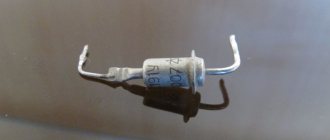
Checking the diode bridge
The diode bridge is an assembly of 4 elements. They are connected so that AC voltage is supplied to two of the 4 terminals, turns into DC voltage and is removed from the other 2 terminals. Zener diodes equalize voltage within a narrow range.
You can ring the LED bridge like this:
- Find which pin to connect the multimeter to by making a conditional numbering.
- Ring the first diode by placing probes on pins 1 and 2.
- Test the second LED by connecting probes to pins 2 and 3.
- Measure the parameters of the third diode by connecting probes to pins 1 and 4.
- Determine the serviceability of the fourth element by placing probes on pins 4 and 3.
- View the readings on the scoreboard.
Voltage stability is checked in the maximum range mode - 220 V. It is increased gradually and stopped supplying until current flows through the circuit.
You will need to place the black probe on the anode, the red one on the cathode, and then connect the anode to the current limiting resistor, and the cathode to the power source.
Checking with improvised materials
To detect faults in LEDs, an LED tester is used, made from improvised means - several AA batteries connected in parallel, or a powerful “Krona”.
The tester is also assembled from an unnecessary charger for a phone or other electrical device. Cut the connector at the end of the cord and strip the wires. Connect red (plus) to the anode, and black (minus) to the cathode. If there is enough voltage, the LED will light up.
Flashlight chargers are useful if a light bulb or strip with more powerful LEDs is faulty.
Other verification methods
In addition to a multimeter, you can check LEDs using a battery.
The best option is a CR2032 battery, which is used in the computer motherboard. Its voltage is 3 V, which is enough for most LEDs. It is possible to use 4.5 or 9V batteries, but in such cases you will need to connect a ballast resistor, which gives a voltage drop to safe levels. For Krona you will need 750 Ohms, for 4.5V batteries - 150-200 Ohms.
The LED strip can be checked with a 12 V battery. These are found in remote controls and doorbells. By connecting the contacts of the tape to the corresponding poles of the battery, areas with burnt-out elements are determined. No less problematic elements are the connection areas of individual parts of the LED strip - connectors that oxidize and stop conducting current. Before you start dialing, you need to check their condition - perhaps the problem lies there.
Important! If you need to test a UV LED, you should be careful when connecting it to a power source. Such devices are sensitive to overvoltage and easily fail. The nominal value for which the ultraviolet LED is designed is 3.4-4 V, these figures cannot be exceeded.
Light Emitting Diode Tester Circuit
If LED bulbs need to be checked frequently, a multimeter with a series resistor is not enough. By smoothly rotating the potentiometer, the maximum brightness of the LED is achieved, the resistance is displayed on the screen.
Important! This method causes the LED to burn out if the resistance inadvertently drops below the limit level.
To determine the exact parameters, you can make an attachment to the multimeter with your own hands.
- remove the block and fastening elements from the Krona battery;
- find a body of suitable size and attach a block to it;
- make pins to connect to the multimeter;
- cut out the board and install a connector for diodes and a power button on it;
- solder a 0.25 W resistor on the reverse side;
- install the structure into the housing;
- connect the wires;
- screw it to the multimeter;
- set the maximum voltage to 20 V.
After connecting the LED element and pressing the power button, you can see whether the light bulb is working, the pinout and the level of voltage drop are quickly determined.
LED voltage and current tester circuit
A more effective device, assembled with your own hands based on the K155LN1 microcircuit and a resistor, which allows you to identify broken diodes and elements with internal breaks.
Important! To check the current and volt parameters, a circuit powered by a Krona battery is suitable. The meter does not require voltage stabilization and is mobile.
It is advisable to make a printed circuit board, attach it to the battery and install it in a plastic case. A voltage of 9 V and a current of up to 30 mA eliminates the possibility of LED elements burning out during testing. The circuit consumes minimal current, so the battery lasts for a long time.
The current is measured by a multimeter set to constant current. To measure voltage, special loops are mounted on the device, connecting the homemade product with a multimeter.
Microcircuit and other parts
When making the latest model with your own hands, the LM317L microcircuit is used, which regulates the voltage, and some other elements:
- Schottky diode, which prevents the flow of electric current in the opposite direction;
- potentiometer that changes resistance within 0-500 Ohms, which allows you to change the output voltage to adjust the current;
- a resistor that stabilizes the current at 30 mA.
If you do not include a resistor in the circuit, a current of 300 mA will flow to the LED during testing and it will burn out.
Determining LED voltage and current
With a do-it-yourself device with the LM317L microcircuit, you can check any LEDs (SMDs are pressed against the contact pads on the board).