“Ringing” of the midrange and high-frequency speakers, will there be consequences for the voice coil?
Sometimes in amateur radio practice there is a need to make sure that the microphone is working. In order to know how to ring a microphone with a multimeter, you need to know the structure of the main models. The most common designs, which are used in almost all household gadgets, are electret microphones.
However, in practice, carbon, electrodynamic, electromagnetic and tape may be encountered. It is quite simple to check such a device with a tester. A carbon microphone is a sealed round chamber in which carbon powder is filled between two metal plates. One of them, thin and elastic, is a membrane. It’s easy to check such a microphone with a tester. The resistance of carbon powder, depending on the type, can range from 50 to Ohms.
If you connect the tester to the contacts in resistance measurement mode and hit the membrane, you will notice a change in the readings. The most common malfunction of a carbon primer is dirty contacts or broken wires. Electromagnetic and electrodynamic microphones have a lightweight moving coil in their design, which has low resistance. Usually it is measured in tens of ohms.
Such a coil is tested by a break tester. Some devices include a matching transformer. The resistance of its secondary winding can be kOhm. Checking a microphone with a multimeter involves determining the integrity of the transformer windings and coil. In order to check the coil of the device with the matching transformer, the housing will have to be disassembled. A condenser microphone is a container formed by a thin membrane coated with metal and a massive base.
For such a device to operate, a polarizing voltage must be applied between the plates of the capacitor. A field-effect transistor cascade is built into the case and there is space for installing a power battery. An electret microphone is a type of condenser microphone. In this design, the flexible electret membrane is the charge carrier. Miniature capacitor capsules have a linear frequency response, good sensitivity and are used in smartphones and other consumer electronics.
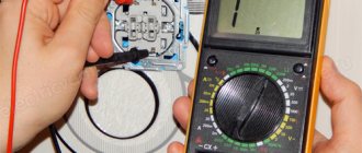
You can check the electret microphone with a tester or multimeter by first removing it from the circuit. The resistance is checked at the measurement limit of 10 kOhm. The resistance values of a small-sized capsule are usually in the range of kOhms.
Usually this value is given in the passport. If it is missing, you need to rely on the specified data. When measuring resistance, polarity does not matter, so the probes of the device can be connected arbitrarily. If the resistance corresponds to the given data or is close to these values, then the device is considered to be working. If the device does not work, you need to check other circuits. If the tester shows a short circuit or infinite resistance, this indicates that the internal circuit is open or shorted.
Miniature capsules are not dismountable and a faulty device needs to be replaced. There are times when the interlocutor on a mobile connection does not hear anything. The transmitter has nothing to do with this situation, since the call signal reached the subscriber.
The reason is a microphone malfunction or poor contact. The case of the mobile device must be carefully opened, the battery and card removed, and the board with radio elements removed.
In some models, the microphone is soldered into the board, but sometimes it is connected to the circuit through spring-loaded contacts. Moreover, the module itself is inserted into a plastic box with another pair of contacts. This results in a double connection through the contacts. If there are no readings when checking with a multimeter, then you need to open the box, remove the capsule and ring it directly.
After cleaning them and slightly bending them, speech transmission is restored. When checking a working microphone on a phone with a multimeter, it rings like a diode. There are situations when the subscriber hears a voice, but it is greatly distorted. This is usually caused by moisture getting inside the module. If, after drying the device, audibility does not improve, the microphone needs to be replaced.
Home Blog Contacts. Home Blog Microphones. How to ring a microphone with a tester Sometimes in amateur radio practice there is a need to make sure that the microphone is working. How to check the performance of a microphone with a multimeter An electret microphone is a type of condenser microphone. How to check the microphone on a phone with a multimeter There are times when the interlocutor on a mobile phone does not hear anything.
Back to services. Request a call. Enter your contact phone number and we will call you back within 5 minutes. I agree to data processing. Submit your application. I agree to the processing of personal data.
What to do if the speakers on your computer don't work
Ordinary, non-professional speakers are a fairly simple device with a small number of components.
Replacing one of them is not a difficult task for a person who has skills in working with radio and electrical engineering, and can be done for someone who knows how to solder and theoretically knows how removable equipment for sound output works.
However, in many cases you won't even have to change the speaker or transformer. The malfunction may not be caused by a failure of some part, but by an easily repairable failure.
Checking speakers with a multimeter and identifying faults
Any multifunctional multimeter tester includes an ohmmeter. An ohmmeter is a measuring device that can be used to measure the electrical resistance of a circuit, a section of an electronic circuit, and determine the nominal resistance of a resistor. Also, using an ohmmeter, you can check the serviceability of most widely used radio components, such as resistors, diodes, inductors, transformers, fuses. Using an ohmmeter, you can check capacitors for electrical breakdown of the plates, detect a break or breakdown of pn junctions in transistors and diodes, and assess the integrity of electrical connections and printed conductors on the board. Designation of an ohmmeter on a circuit diagram. In the circuit diagram, the ohmmeter is depicted as a circle with two terminals, which in practice are measuring probes. Let's consider the main points of carrying out resistance measurements using digital multimeters of the DTx, M83x, MAS83x and the like series.
How to test a speaker or earphone
VIDEO ON THE TOPIC: 12. Checking the speaker with a multimeter. Burnt or not!?
Login: Password: Remember me Registration Forgot your password? Pages: 1 2 Next Level N. Messages: Points: 32 Registration:
Impedance is the complex resistance of an electrical circuit consisting of a resistor, capacitance and inductance, which acts when high-frequency alternating current enters the input of this circuit. Depending on the values of capacitance and inductance, the impedance of the circuit changes. At low frequencies, the active resistor element has a greater influence. At high frequencies there are reactive elements of capacitance and inductance. Acoustic systems consist mainly of power amplifiers, frequency crossover filters and loudspeakers. The bandwidth is Hz.
In the modern world, speakers have become widespread, because without these devices it is impossible to produce televisions, mobile phones, tablets, speakers, headphones and other audio equipment. And more often than not, their work remains unnoticed by people until the speaker fails. A speaker, often called a loudspeaker, is an electrical device that converts an electrical signal into sound.
Multimeters and instructions for using the tester
A multimeter is a device for checking the electrical parameters of various equipment and electrical parts. This tester can check the connection between conductors, measure voltage, current and resistance, and also perform some other operations. How to use a multimeter - read our article!
- Types of multimeters and the principle of their design
- Power supply for multimeters
- How to test a multimeter for functionality?
- How to use a digital multimeter?
- How to check the functionality of a capacitor with a multimeter?
- How to test a relay for functionality with a multimeter?
- Video for dummies: How to use a multimeter?
Types of multimeters and the principle of their design
The most common types of multimeters are analog and digital. Let's look at how they are designed and work below.
Analog
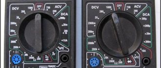
These are old-style testers that look like boxes with a glazed arc-shaped scale and a spring-loaded pointer. Often there is a mirror arc on the scale so that when you look at the arrow you can align the arrow with its reflection. This way, when measuring, you are looking exactly perpendicular to the scale, rather than at an angle, and it will be more difficult for you to make a mistake. The measuring panel has many parallel arc scales for different types of measurements:
One of the main advantages of an analog multimeter is its low price and measurement accuracy that is quite sufficient for everyday purposes. Moreover, most analog multimeters have a built-in special resistor to adjust the position of the arrow exactly to “0”. For adjustment, a resistor head is used, similar to a screw slot, located below the measuring scale approximately at the point where the arrow is attached.
Digital
These multimeters are more modern and look like oblong black boxes with a large liquid crystal display for digital readings. These devices got their name because the analog signals entering the device are converted into digital form in an analog-to-digital converter (ADC). Such devices are more expensive than analog ones, but their size and weight are somewhat smaller, and it is more convenient and faster to work with them.
Some models are well suited for working in complete darkness due to the ability to illuminate the indicator panel (and electricians often have to work in dark rooms). You simply press a button and the panel lights up. In addition, you can find a model with the ability to record the readings taken into the device’s memory and subsequently transfer this data to a computer for further analysis. To do this, just press a special button.
Typically, digital devices are used by professional electricians, electronics engineers and engineers.
Power supply for multimeters
Both types of multimeters require batteries to operate. Some types of indicators can measure voltage without batteries, but all other types of measurements still require a source of energy. These can be different types of batteries - AA, AAA, “Krona” (“6F22”) or rechargeable batteries. There are models with built-in batteries that can be recharged.
It is very good if the multimeter has an auto-shut-off function when inactive. It often happens that the measurements are taken, the broken device is repaired, test/adjustment runs begin, and the multimeter is left in the on state. Within a few hours, the battery may well be discharged. Therefore, for those who constantly use a measuring device, it is better to choose a model with auto shut-off.
How to test a multimeter for functionality?
To check the functionality of the multimeter, as a rule, you need to perform the following steps:
- Set the probes to resistance test mode (R). In this case, the black wire should be inserted into the “COM” or “-” connector, and the red wire into the “Ohm” (Ω), or “omega” connector.
- Move the large dial pointer to the “ring” position.
- Align the metal ends of the probes with each other.
After these actions, a piercing sound signal should be heard. If there is no sound, then the multimeter is not working and is not even suitable for checking the wiring.
How to check a car amplifier at home
In order to check the performance of a car amplifier at home, you can use any unit with a constant output voltage of 12 to 14 volts, or a computer unit that has the voltage necessary to start the amplifier. The source power must be at least 200 volts and before turning it on, be sure to set the power volume control to minimum. The repair process should always begin with a visual inspection of all radio components on the amplifier circuit board. A standard car amplifier model consists of three main components:
- an input voltage converter unit, which changes the unipolar input voltage of the vehicle's on-board circuit into two polar ones with an increase in voltage up to 20 Volts;
- power amplifier unit, often it is made of bipolar transistors, which are installed on radiators necessary to increase the heat dissipation area. Powerful output stages at maximum power get very hot, so a poor, leaky connection between the transistor plane and the heat sink will certainly lead to its overheating, and, accordingly, to breakdown;
- a frequency control block used to change the sound timbre. A common malfunction of this unit is associated with a deterioration in the smoothness of changes in resistance by variable resistors.
After opening the case, you should carefully inspect every detail of the amplifier, paying special attention to:
- blown fuses. An unbroken fuse-link thread should be visible through the glass flask;
- resistors should not have visible carbon deposits indicating their burnout;
One of the most common malfunctions of failed car amplifiers is related to the breakdown of the inverter power supply. This node consists of:
- input filter capacitors with large capacity;
- pulse transformer;
- transistor converter and microcircuit for acting as an inverting device;
- rectifier diodes working in pairs;
- a smoothing chain consisting of a choke and several electrolytic capacitors.
Read more: Oil change Volkswagen Amarok
In any case, any burnt parts found must be replaced with new ones. In this case, neither the fuse nor the resistor installed in the sound-reproducing equipment fails without associated reasons. The condenser may dry out and swell over time. More accurate research and testing of amplifiers is carried out using a millimeter and an oscilloscope.
How to use a digital multimeter?
A digital multimeter can be used for many standard operations: checking resistance, determining current, determining DC or AC voltage, and determining the health of a transistor. Instructions for use for beginners are as follows:
Principle of use
The general rule is this: start measuring with a larger value on the pointer so as not to damage the sensitive device. For example, if you want to measure the resistance of an element, knowing approximately that it is about 1 kOhm, then set the adjustment knob to 2 kOhm.
Resistance measurement
Resistance is defined as follows:
- The black wire is inserted into the “COM” connector, the red wire into the “VΩmA” connector.
- Next, a black probe is applied to one leg of the element, and a red one to the other.
- If the element being tested is soldered into the board, one leg must be unsoldered and raised so that there is no contact with the board.
- It doesn’t matter which probe is applied to which leg.
- The dial indicator should be set to the voltage measurement sector (with the Ω symbol) and the order of magnitude of resistance that you are counting on.
Voltage measurement
When carrying out measurements, it is necessary to distinguish what type of current is being measured - direct or alternating, and connect the probes accordingly. Direct current is abbreviated as “DC” (direct current), and is often represented graphically simply by a short horizontal line (-). Alternating current is abbreviated as “AC” (alternating current) and is usually represented by a wavy line (
Voltage is measured as follows:
- The black wire should be in the “COM” connector, the red wire should be in the “VΩmA” connector.
- The disk must be installed in the sector for measuring voltage - for alternating in “ACV” (
), for constant in “DCV” ( – ), and the exact position of the disk is determined in accordance with the value of the measured voltage with a known excess of the measured value. For example, to check the voltage in a 220 Volt outlet, the disk must be set to 750 Volts.
- It doesn’t matter which probe you put where. Just try to keep your fingers and hands from touching live parts and the tips of the probes.
- After the probes touch the conductors, the measured voltage will be indicated on the display.
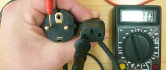
How to make a call with a multimeter?
This option is used for “diagnosis”, for example, of wires and electrical wires. It is implemented as follows:
- The line is de-energized, for which the plugs are unscrewed, or the central apparatus is turned off.
- The wires are released, for example, the twist in the distribution box is unscrewed, the terminals in the socket are unscrewed.
- The two ends are closed, from either side.
- The tester is turned on and checked for functionality by connecting the tongs, after which a signal should sound and the value “0” or close to this parameter will be displayed.
- The multimeter probes are applied to the ends of the wiring. If a sound is made and a value close to zero is displayed, then the wire is not damaged.
How this tester function is used can be clearly seen in the following video:
Using other features
Most types of multimeters have an audible indication mode for a short circuit. If there is direct contact between the probes, the multimeter emits a high-pitched squeak. This mode is convenient to use when checking the integrity of wires, the presence of contacts between terminals, “continuity” of diodes and other elements. In this case, you do not need to hold the multimeter in your hands; you can even put it in your chest pocket, for example. If desired, you can choose a multimeter with a light indication.
In addition, some multimeters have the ability to determine the capacitance of capacitors, the inductance of coils, the gain of low-power transistors, the oscillation frequency (usually up to 20 kilohertz), the room temperature using a built-in thermistor, the temperature of objects and environments using the included thermocouple.
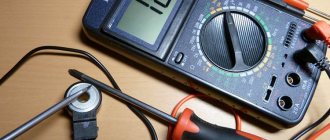
How to test an audio amplifier with a multimeter
In order to correctly and with a high degree of probability find a failed output stage transistor, thereby checking the sound amplifier, it is best to unsolder each of these semiconductor devices. However, this procedure is very labor-intensive and will take a lot of time, so the output transistors are checked directly on the circuit board, switching it to resistance measurement or continuity testing. If, when connecting the multimeter chips to the legs, the resistance in one direction and the other is the same or very low, then this means the transistor is broken and requires replacement.
You can also ring diodes, which must pass current in one direction, that is, if you touch the ohmmeter probes in one direction, the resistance should be low, then in the other direction it should be more than 100 kOhm.
You can ring the emitter circuit of the output stage, but to do this you need to know the wiring of the transistors, that is, where its base, emitter and collector are. Checking the sound amplifier involves touching the emitter of the output stage transistor with one probe, and the terminal going to the speaker with the other. The continuity test should show zero resistance or a value close to it. Even a person unfamiliar with electronics can understand how to test an audio amplifier with a multimeter.
How to check the functionality of a capacitor with a multimeter?
A capacitor is an element of an electrical circuit that has two conductive plates with a dielectric spacer between them. Most often, all these paddings are rolled into a small roll, packed into a small cylinder. Two legs protrude from the cylinder - these are the leads of the storage plates. The working capacitor has no contact between the plates, so the capacitor simply does not pass direct current through itself. But alternating current passes through the capacitor.
There are polar and non-polar capacitors. On polar ones, most often there are markings on only one leg, for example, only “+” on the side wall next to the leg. Polar ones must be used in the circuit exclusively in the oriented state: “+” must be soldered to “+”, “-” to “-”. Incorrect placement of the polar capacitor can even lead to a small explosion. And non-polar capacitors can be inserted into the circuit without worrying about the correct orientation.
So, the verification procedure is as follows:
- If the capacitor is sealed into the circuit, we solder one of its legs, whichever is more convenient.
- Set the multimeter to “dialing” mode.
- We apply a probe to one leg of the capacitor. If the element is polar, respectively, the black wire is to “-”, the red wire is to “+”. Don't get confused.
- If the number “1” lights up on the display and the measuring device does not beep, this means that the capacitor is not “broken,” that is, the plates are insulated and, most likely, the capacitor is working. Otherwise, the capacitor has lost its functionality and must be replaced.
How to test an electrical capacitor using a conventional multimeter is described in the following video:
Types of faults
Malfunctions are divided into software failures, hardware failures and connection problems. The latter include: incorrectly inserted or fallen out plug, plug, lack of power supply, etc.
Software
The reason is that a working sound card is not processing or transmitting data correctly. This may be due to the lack of a driver or its incorrect operation. You need to go to the official website of the sound card manufacturer and download the latest version. If, on the contrary, the devices stop functioning after the update, you should install the previous version of the driver, which is also available on the official website.
Hardware
The problem is the failure of one or more elements of the device. It could be a speaker, transformer, switch, etc. To find the breakdown, you need to carry out diagnostics. To do this, first eliminate the most easily fixable failures, and then check all the elements using a multimeter.
How to test a relay for functionality with a multimeter?
A relay is an electrical device that allows you to switch more powerful electrical appliances using low-power signals. Relays are often used in auto electricians; such relays usually have 5 flat contact pins. An inductor is usually used as a control element. The diagram for the mutual connection of the terminals to each other is usually shown directly on the relay body, especially if the relay is not small.
Some terminals should be in contact with each other, some should not. It is impossible to fully test the relay for functionality without using a power supply. It is needed to supply voltage to the control terminals.
Checking the relay consists of the following steps:
- Turn on the multimeter in “dialing” mode.
- First you need to make sure that in the disconnected state there is no situation “all terminals are connected to all” or there is no contact where it should be. Which terminal should be connected to which depends on the specific circuit. If there is “all to all” contact, the relay is faulty, this should not happen.
- We check from the diagram which terminals are shown as open. There should also be no contact between them.
- If, in the off state, the contacts between all terminals are in the same state as they should be, the relay must be connected to the circuit or power supplied to the control terminals. The inductor should operate and close the circuit, that is, contact should appear between the controlled terminals where there was none when the power was turned off, and vice versa. If no contact appears, then it is clear that the coil is not firing and the relay cannot operate normally.
How to clean your smartphone speakers
If, after checking the speakers and installing programs, a person simply discovered that nothing helped, then most likely it is necessary to clean the speaker. You can use different devices to clean the speaker:
- Toothbrush. You cannot use a hard brush in this method. If the user uses it, then the phone does not need to be disassembled. You may need to gently walk over the speaker a few times to dislodge some of the bristles;
- Needle. This is an extreme method that also works. It is necessary to pierce the speaker dirt with careful movements, and then fluff it up;
- Gum. This method is not used by professionals, but to use it, you need to attach it to the mesh and then peel it off. A more effective combination is to first go through with a needle, and then remove the remains with chewing gum.
Once the speaker is cleaned, it's worth going through a hydrogen peroxide solution to remove any residue, as well as any trapped dust. The main thing is not to pour too much hydrogen peroxide, as it can get inside and oxidize some microcircuits. To prevent this from happening, you should carefully use a cotton swab dipped in the solution.
This way, cleaning should be simple and easy. Of course, it is better to trust a professional, but, as experience shows, many people clean speakers at home.