How to check a resistor for serviceability using a multimeter
A resistor is an element that no circuit can do without. Therefore, it is not just desirable, but necessary to know how to correctly check the serviceability of a resistance (resistor) using a measuring device (multimeter).
Marking of SMD elements
Checking for a break
Validation check
What is clearance and why is it important?
Checking the variable resistor
Verification algorithm
Despite the fact that there are a large number of modifications of resistors, the algorithm for checking most of them is reduced to the following three stages, namely:
1. Visual inspection.
2. Testing the part for breakage or breakdown (an extremely rare occurrence with resistors).
3. Checking compliance with the nominal value of the resistance parameter.
The first three points will most likely not cause any difficulties, but the third one needs to be discussed in more detail, which is what we will do.
After all, in order to check compliance with the nominal value, you need to know this very nominal value. And if you have a diagram of this device, then everything is simple.
We read the diagram, find the required element and find out its parameter in the accompanying documentation. But here’s the problem: most modern devices are not equipped with circuits. The way out of this situation is to determine the resistor value by marking.
Types of markings
In Soviet times, all the necessary information about resistors was indicated on the product itself, and if the element was damaged, then its parameters were indicated in the accompanying technical documentation.
At the moment, color marking of the product has been adopted, which allows, even if the element is severely damaged (and in the absence of circuits), to determine the nominal value and resistance tolerance.
The decoding of this marking is as follows:
Marking of SMD elements
But mounted resistors mounted using robotic systems are digitally marked in the form of three numbers. The first two indicate the resistance value, but the third indicates the multiplier:
So, we have figured out how we can determine the value of the resistor we are interested in, now let's return to our algorithm and start checking the elements of interest.
Inspection
In the vast majority of cases, the resistor stops working due to its overheating, which is very easy to determine by the blackened body of the part.
As you can see from the photo, part number 1 is definitely a replacement, but the neighboring ones require checking.
Checking for a break
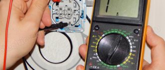
Checking for a break is performed as follows: take a device (multimeter), place the regulator and probes as shown in the photo below
Then we touch the ends of the measuring probes to the terminals of the resistor and if we see “1” on the display, it means that this element is broken and should be replaced.
Validation check
If you have soldered a resistor or want to check a newly purchased one, then follow these steps:
We take the device, connect the probes to the appropriate connectors, and set the measuring limit on the regulator as close as possible to the expected value of the resistor. And we measure the parameter.
We read the readings from the device and compare it with the nominal value. And I want to tell you that in 99 cases out of 100 they will be different. Since all resistors have their own tolerance.
What is clearance and why is it important?
This parameter is set by the manufacturer and indicates how much the product parameter may differ from the nominal value. If you install a part with a parameter that does not correspond to the required one, this can lead to rapid overheating and failure of the resistor. And, accordingly, the inoperability of a recently repaired device.
So, it seems clear how to check a standard resistor, but we’ll talk about how to check a tuning (variable) resistor further.
Checking the variable resistor
Checking such resistance is actually not much different from checking a regular resistor, with the exception of a few points, namely:
The trimming resistor has three output legs, and if you measure between “1” and “3”, the device will show a value close to the resistor’s value.
If you connect the measuring device to terminals “1” - “2” or “2” - “3” (there is no fundamental difference), then the resistance value (when adjusting the trimming handle) should smoothly change from zero to the nominal value obtained when measuring at pins “1” - “3”.
If during adjustment the instrument readings periodically change by 1 (infinite resistance), then the trimmer is unusable and needs to be replaced.
Conclusion
This is how a resistor is checked using a measuring device (multimeter). If you found this article useful, please rate it with a like.
Thank you for your attention!
Marking of SMD elements
Surface-mounted components (for example, SMD resistor, diode, capacitor, etc.) began to be marked with numbers, but due to the small size of the parts, this information needed to be encrypted. For resistances, in most cases, a designation of three numbers is accepted, where the first two are the value, and the last is the multiplier (see Fig. 3).
Rice. 3. An example of decoding the value of an SMD resistor
How to check a diode bridge
Sometimes there is a situation when you need to check the functionality of a diode bridge. It looks like an assembly consisting of four semiconductors. They are connected in such a way that the alternating voltage supplied to two of the four soldered elements becomes direct. The latter is removed from the other two terminals. As a result, the alternating voltage is rectified and converted into constant voltage.
Essentially, the principle of verification in this situation remains the same as described above. The only feature here is the determination of which output the measuring device will be connected to. There are four connection options that you should call:
- conclusions 1 – 2;
- conclusions 2 – 3;
- conclusions 1 – 4;
- conclusions 4 – 3;
When checking diodes (regular and Schottky) with a multimeter, you will get a certain result. Now we need to understand what it could mean. Signs that indicate the health of the semiconductor include the following:
- When connecting a part of the electrical circuit to the device, the latter will output the value of the available direct voltage in this element;
- Different types of diodes have different voltage levels, which is why they differ. For example, for germanium products this parameter will be 0.3-0.7 volts
- When connected in the opposite way (the probe of the device to the anode of the product), zero will be recorded.
By checking each output, you will get four results. The obtained indicators should be evaluated according to the same principle as for an individual semiconductor.
Reverse check
If these two indicators are met, then the semiconductor is working adequately and the cause of the failure is not in it. But if at least one of the parameters does not correspond, then the element is considered unusable and must be replaced. In addition, it should be borne in mind that it is not a breakdown, but a “leakage” that is possible. This unpleasant defect can appear during long-term use of the device or poor-quality assembly.
If there is a short circuit or leakage, the resulting resistance will be quite low. Moreover, the conclusion must be made based on the type of semiconductor. For germanium elements, this indicator in this situation will range from 100 kilo-ohms to 1 mega-ohm, for silicon - thousands of mega-ohms. For rectifier semiconductors, this figure will be many times higher.
As you can see, it is not so difficult to assess the performance of semiconductors in any electrical device on your own. The above principle is suitable for testing diode elements of various types and types. The main thing in this situation is to correctly connect the measuring device to the semiconductor and analyze the results obtained.
Two Schottky diodes.
Principle of operation
The operation of any ohmmeter (including modern digital meters) is based on the basic postulate of electrical engineering - Ohm's law. According to its conditions, the greater the resistance, the less current passing through it - at a constant supply voltage.
An ohmmeter requires a power source to operate. A powered electrical circuit is formed in which the device, taking into account the supply voltage and the current flowing through the element being measured, determines the resistance.
Modern digital multimeters use a 9-volt battery.
In China, you can order an 8.4 V nickel-cadmium battery - 7 rechargeable 1.2 V cells, packed in a case of the same size, with a capacity of up to 200 milliamp-hours - it will provide power close to 9 V, which is why the device will not output significant error.
This method is a solution for those who often measure the resistance of resistors, spirals and windings at work, “ring” cable lines, etc.: after about 1000 measurements, a regular battery would “die.”
Digital multimeter
The main feature of a digital multimeter is the presence of a screen; the measured value is clearly displayed on it. The operating principle of the device is based on comparing the measured signal with a reference signal; for this, an analog-to-digital converter is used.
To carry out a measurement, the tester is connected with a set of wires to the element being measured. At one end of each wire there is a plug intended for installation in the meter socket, and at the other there is a contact probe. The procedure for measuring the resistance of a resistor with an electronic multimeter can be represented as the following:
- Pressing the ON/OFF button turns on the device.
- The probes are connected to the two ends of the resistor, the reverse ends of the wires to the Ω and COM connectors.
- The switch sets the approximate resistance.
- If a unit is displayed on the indicator, the switch should be moved up one position, i.e., increase the measurement limit.
- If, when taking readings, numbers other than one are displayed on the screen, this will be the resistance value.
In the same way, you can measure the resistance of the pn junction of a semiconductor. A digital device is convenient to measure constant resistance, but it is useless when you need to find out its variable value. For such measurements, it is preferable to use a pointer instrument.
Pointer device
The very first measuring instruments were equipped with a pointer device. This device was an electromechanical head. Structurally, it is made in the form of a frame located in a magnetic field. An electrical signal is supplied to this head through various resistances. Depending on the current strength, the arrow in the frame deviates, settling in a certain position. The range of the needle deflection is calibrated, according to these values and the required value is calculated.
The technical capabilities of an analog tester are largely determined by the sensitivity of the magnetoelectric measuring device. Its main advantage is its inertia and immunity to interference during the measurement of DC voltage and resistance value.
Pointer instruments are ideal for displaying signal dynamics. The tester instantly shows its change. At the same time, such a device has a large error when measuring in high-resistance circuits, and there is some difficulty in interpreting the measurement results.
The device is turned on according to the instructions indicated on the back of the battery cover. The switch button selects the operating mode for a constant, variable value or resistance (respectively “—”, “~”, “Ω”). A double click is used for a measurement pair. The calculation range switch is set to a fixed value corresponding to the expected measurement value.
Before measuring the resistance value, the tester is adjusted by rotating the zero knob until the arrow points to the “∞” value. When choosing the “Ω” measurement range, the resistance values are not marked with the maximum numbers in this range, but have the following form: x1, x10, x100. This means that the resulting value will be measured in Ohms, kOhms, and MOhms. Active resistance is measured from a direct current source (battery) installed in the device.
Having turned on and prepared the tester, you need to attach the probes to the object being tested. According to the arrow readings, the result will appear on the measuring scale, which is then multiplied by the range multiplier.
Using a Megger
A megohmmeter is a specialized measuring device. Before starting measurements, you must strictly adhere to the requirements of the PUE (electrical installation rules). The basic rules include:
- Measurements are taken at the limit of the tester, which exceeds the highest possible resistance value. If such a value is unknown, then they start with the maximum possible limit, which is reduced to the minimum possible to improve the accuracy of the result.
- Before checking the resistance with a tester, you will need to make sure that the object being tested is de-energized.
- All elements with reduced insulation, capacitors, semiconductors are short-circuited before testing begins.
- During the measurements, the test object is grounded.
- After completing measurements, especially for devices with large capacitance (for example, long-distance wires), before disconnecting the probes of the device, it is necessary to remove the residual charge by shorting it to ground.
- Taking readings of the insulation resistance of power and lighting wiring occurs with switches turned off, fuses removed, and lamps removed.
- It is strictly prohibited to measure insulation near high voltage lines or during a thunderstorm.
A megohmmeter is a complex device consisting of a current generator and a measuring head. Also included are: current-limiting resistors, terminal blocks, a dielectric housing and a mode switch.
The device has three terminals for external connection of wires. The ground is connected to one, the line to the other, and the screen to the third. Which wire is connected where is indicated in the instructions for the device.
The ground and line terminals are used for any insulation readings relative to the ground loop, and the shield contact is needed to reduce the influence of leakage currents. Such currents appear when measuring between two wire strands located parallel to each other. The screen contact is connected with a special wire that comes with the device.
After connecting all the probes on old-style devices, you will need to twist the knob, which will ensure the operation of the internal generator and the supply of voltage to the object being tested. In modern devices, a button is used instead of a handle, and power is taken from installed batteries or galvanic batteries. The generator voltage can range from 100 volts to 2.5 kV. As soon as the voltage is applied, for a pointer instrument, readings are taken from the arrow on the scale corresponding to the selected range, and for a digital type of instrument, readings are taken in the form of numbers on the indicator.
Checking an element on the board without soldering
The search for a faulty element usually begins with semiconductor devices - these are transistors, diodes, thyristors, optocouplers, etc., since they are less reliable than resistors, which are the last to be tested with a multimeter. Before checking the resistor with a multimeter, carry out a visual inspection. If blackening or darkening has formed on the body of the element, this indicates that the resistance has overheated due to a current exceeding the power of the resistor. All resistor values have a range of powers from 0.125 W to several tens and even hundreds of W. Consequently, resistances of the same rating and different power are designed for different operating currents.
If the resistor has a blackened body, then you need to look for the fault in the neighboring components of the board, which are the culprit for overloading the resistor
Also, before checking with a multimeter with tweezers, carefully shake the element terminal. If the output is shaky, then this indicates their breakage
This resistance requires replacement. To correctly assess the resistance value of a multimeter, its batteries must not be discharged. To assess their suitability, it is enough to set the audio test mode and short-circuit the tester probes. If the batteries are good, the alarm will be loud enough.
Before checking the resistance value of a component, you need to set the required resistance limits on the device that will be used for measurements and close the probes. The display should show zero. If the measurement is carried out in Ω (Ohm) mode, then the display will show the resistance of the meter cords, which must be subtracted from the reading when measuring element resistance. For reliable measurements, you do not need to touch the metal ends of the probes with your hands.
Before checking the resistor with a multimeter, the resistance terminals are cleaned of oxide. When checking, the tolerance percentage of the resistance value is also taken into account. For example, you are testing a 1 Kom resistor with a tolerance of ±10%; if the element is working, the display should display a value of 0.9 Kom - 1.1 Kom. With other resistance values, we can assume that this element is faulty. If the resistor is part of an electrical circuit on the board, then one end of it must be disconnected or unsoldered, since the components of the electrical circuit introduce significant distortions into the measurements.
Table of resistance ratings by color stripes
Also, before testing any components of an electronic board, including resistors, you need to turn off the supply voltage, unless you are measuring the operating mode of electronic circuit components on a printed circuit board. All of the above also applies to wirewounds and SMD surface mount resistors. Below is a table of codes for high-precision resistors:
Code table for high precision resistors.
It will not be possible to check the resistance value of the resistor on the board without desoldering it, since other elements of the circuit have their own resistance and will distort the readings. Therefore, when measuring, it is necessary to unsolder one terminal of the element. This also applies to SMD resistors. However, if it is not possible to unsolder the pin without damaging the contact pad, you can carefully use a sharp knife to cut off the printed circuit board track a few millimeters from the pin of the element. After checking with a multimeter, the cut track is soldered.
This method is used when testing without output SMD resistors. One end of these elements cannot be unsoldered; in order to completely remove them from the board you need to have two soldering irons or a special soldering hair dryer. To check the variable resistor with a multimeter, it is completely evaporated from the board. Test a variable resistor (potentiometer) between the constant and variable (slider) terminals. Smoothly moving the middle terminal, observe the readings of the device. With a working variable potentiometer, the readings change smoothly, without surges or breaks. Then the same measurements are taken between the other permanent pin and the slider. It is convenient to check variable potentiometers on a dial tester, monitoring the smooth movement of the device needle.
Resistance check
How to measure resistance when the value is unknown
Setting the highest threshold when measuring resistance is not so important. In ohmmeter mode, you can select any range. If the device displays “1”, which means infinite charge, the threshold must be increased until the desired result is displayed on the screen. In this simple way, the presence or absence of a denomination becomes completely unimportant.
Analog multimeters are ideal test equipment for measuring resistance. They are relatively cheap and offer a fairly good level of accuracy and overall performance. They typically provide a level of accuracy that is more than sufficient for most jobs.
Helpful information
If a piece of equipment is properly operated and is not subjected to excessive mechanical (chemical, thermal) influences, this circuit element rarely fails. In order not to waste time, the resistor is checked last, after testing other rads/parts - capacitances, inductances, semiconductors, and so on. But only if there are no obvious signs of damage to R.
Before starting to check the resistor, you need to clarify such a parameter as the permissible deviation from the nominal value. All parts of this group (with the exception of precision, special precision) have a resistance that differs within some limits from the indicated value. The tolerance is expressed as a percentage (for example, ±10%) and is marked on the part body with numbers or color mnemonics (stripes).
The necessary data can also be found from the circuit diagram, if it is at hand. When checking the multimeter resistor, this is worth taking into account. The readings may differ from the required ones, since the measurement error of the device itself is also added to the tolerance.
Example
If R = 150 Ohm ± 10% (according to the diagram, designation on the case), then the multimeter, when tested, can show a resistance in the range of 135 - 165. And this is considered normal.
On many modern circuits, resistor values are not indicated. This (and other) information can be found in tables that are placed on the reverse side, at the bottom of the sheet, or on the side. In this case, the part has its own designation on the board. For example, R15. Therefore, it is necessary to find the 15th position in the table, and in this line all the comprehensive information on this resistor - its type, resistance value, permissible deviation from the nominal value.
Sometimes a person's body affects test results. Especially when it comes to measurements with a set limit in kOhm. Therefore, during the testing process, it is not advisable to touch the resistor terminals and metal parts of the probes with your fingers. The latter are held by plastic insulators (handles).
It turns out that there is nothing complicated in checking resistors, but a couple of tips will not hurt.
- Before you start working with a multimeter, you should carefully read the instructions for it. Manufacturers are constantly improving samples of measuring equipment, expanding its functionality. For example, if, due to careless handling, the device does not work in the “Ω” mode (partial damage to the internal circuit), it may be possible to check the resistor for integrity in the “test p/p” switch position.
- From the brief guide it will become clear what characteristics of the radio component can be determined additionally (except for the resistance value). Not all models are universal in this regard, and it is sometimes difficult for a person without experience to understand the functionality of a particular multimeter based only on the symbols on its front panel.
What is a multimeter
A multimeter is a device that can measure AC or DC current, voltage and resistance. It replaces three analog or digital instruments at once: ammeter, voltmeter and ohmmeter. It is also capable of changing the main indicators of any electrical network and ringing it. There are two types of multimeters: digital and analog. The first are portable devices with a display to display the results. Most multimeters on the market today are digital. The second type is already outdated and is no longer popular. It looks like a regular measuring instrument with a graduation scale and an analog needle showing the measurement value.
Features of measuring resistor resistance with a multimeter
In order to find out the resistance of the resistor, you need to use a conventional multimeter. The measurement principle is based on Ohm's law, which states that current is directly proportional to voltage and inversely proportional to resistance. Resistance is determined indirectly using the formula R = U/I. That is, with known voltage and current it is easy to determine the resistance.
If dial testers were previously used, today radio amateurs most often use digital multimeters with a rotary switch to check the serviceability of resistors, with the help of which the type of operating mode and measurement range are set.
Digital resistor tester
To measure the value of R, the switch is set to the Ω range. This device comes with one set of probes of different colors. It is customary to insert the red probe into the com hole, and the black probe into VΩCX+.
Types of devices for taking measurements
Almost all multifunctional measuring instruments have the ability to measure the impedance value.
Based on their operating principle and functionality, manufactured devices can be digital or analog. At the same time, their important characteristics are the error and measurement range. Before you start working with the tester, you need to make sure that its batteries are in good condition. If a digital type of device displays a blinking battery indicator, this means that the battery needs to be replaced. For a pointer instrument, a signal to replace the power elements will be the inability to set the pointer to the zero position.
To obtain the correct result, it is necessary not only to use the configured device, but also to monitor the ambient temperature. As is known from the laws of physics, when heated, the resistance value of conductors increases, and that of semiconductors decreases. The optimal temperature is considered to be 20 degrees Celsius.
What are you multimeter
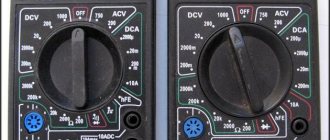
Let's first find out what can be measured using this miracle of a device and what indication is present on its front panel. So, you will be able to see the following symbols:
— OFF This position is self-explanatory and means that the tester is off.
- ACV, this abbreviation tells us that the voltage change is measured here.
— DCV and here we look at constant voltage.
— DCA measures direct current here.
- Ω and in this section the resistance is calculated.
For easier understanding, here is a visual image of a multimeter with explanatory notes
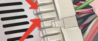
Pay attention to the large circled area with sockets; here you can see as many as three connectors, but there are two wires. This means that to obtain the correct measured data, you need to choose the right sockets. But here, in fact, everything is extremely simple. The black wire always goes into the socket marked COM. But changes between the other two connectors are performed using a red probe
Moreover, in the vast majority of cases, the “VΩmA” socket is suitable for home purposes. In this position, you can perform a continuity test, measure voltage and measure current up to 200 mA inclusive.
But if you need to measure current up to 10 A, then you need to move the red probe into the 10ACD connector.
These provisions are extremely important; if you do not comply with them, the tank will very quickly become unusable.
Also, maybe someone has an old machine lying around with an arrow dial, and so it has exactly the same functionality as a multimeter with an electronic display, but the latter is easier to work with. Since you immediately see the exact value of the measured parameter, and the error on the pointer device is slightly higher.
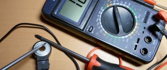
Checking the resistor with a multimeter
For all measurements, regardless of their type, the multimeter probes are connected to the terminals of the radio component. Polarity does not play a role in this case.
On a cliff
The simplest type of testing. Such a malfunction does not appear externally in any way, so it can only be determined with a multimeter. The reasons for violating the integrity of the conductive part are very different - from a manufacturing defect (extremely rare) to the burning of a layer or wire wound on the body of the part.
During such a check, the switch is set to the “dialing” mode. There is sound - everything is normal. If it is missing, the resistor must be replaced.
At face value
This test places the switch in the Ω range. The choice of the required limit has already been discussed. The image size is displayed on the LCD indicator or by an arrow set at one or another digital value (they are indicated on the dial). It's not difficult to count it.
Types of markings
On components produced during the Soviet Union, it was customary to indicate the denomination on the body of the part (see Fig. 1). This option did not require decoding, but if the integrity of the structure was damaged or the paint burned out, problems with text recognition could arise. In such cases, you could always turn to the circuit diagram that supplied all household appliances.
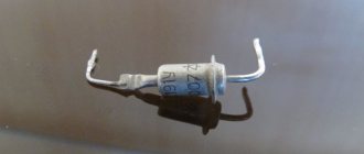
Figure 1. “ULI” resistor, the part rating and tolerance are visible on the body
How to check a resistor with a multimeter without desoldering on the board?
This testing option is only permissible with low-resistance elements. Above 80-100 ohms, it is likely that other components will interfere with the measurement. The final answer can only be given by carefully studying the circuit diagram.
A resistor is one of the most commonly used elements in modern electronics. Its name comes from the English “resist”, which means resistance. Using a resistor, you can limit the effect of electric current and measure it, divide voltage, and set feedback in an electrical circuit. We can safely say that not a single electrical circuit or device can do without this element. That is why it is often necessary to measure the resistance of a resistor with a multimeter and check its performance. This material will tell you how to test the board for functionality with a multimeter.
Checking for a break
Actions are performed in the following order:
- We turn on the device in the “dialing” mode. In Figure 5 this position is marked as “1”. Rice. 5. Setting the mode (1) and connecting probes (2 and 3)
- We connect the probes to sockets “2” and “3” (see Fig. 5). Despite the fact that in our testing polarity does not matter, it is better to immediately train yourself to connect the probes correctly. Therefore, we connect the red wire (+) to socket “2”, and the black wire (-) to “3”.
If the model of the device you are using differs from the one shown in the figure, read the instructions that came with the multimeter.
- We touch the pins of the problematic element on the board with the probes. If the part “does not ring” (the multimeter will show the number 1, that is, an infinitely large resistance), we can state that the test showed a break in the resistor.
Please note that this testing can be carried out without desoldering the element from the board, but this does not guarantee a 100% result, since the tester can show communication through other components of the circuit
Color designation
Now color marking has been adopted, representing from three to six rings of different colors (see Fig. 2). There is no need to see this as the machinations of enemies, since this method allows you to set the denomination even on a heavily damaged part. And this is a significant factor, given that modern household electrical appliances are not equipped with circuit diagrams.
Rice. 2. Example of color marking
Information on decoding this designation on components is easy to find on the Internet, so it makes no sense to present it within the framework of this article. There are also many calculator programs (including online) that allow you to obtain the necessary information.
Troubleshooting algorithm
Visual inspection
Any repair begins with an external inspection of the board
It is necessary to examine all components without instruments and pay special attention to yellowed, blackened parts and components with traces of soot or soot. For external inspection, a magnifying glass or microscope can help you if you are working with dense mounting of SMD components
Torn parts may indicate not only a local problem, but also a problem in the strapping elements of that part. For example, an exploding transistor could drag down a couple of elements in the harness.
An area on a board that turns yellow due to temperature does not always indicate the consequences of part burnout. Sometimes this happens as a result of long-term operation of the device; when checked, all parts may turn out to be intact.
In addition to inspecting external defects and traces of burning, it is worth sniffing to check if there is an unpleasant odor like burnt rubber. If you find a blackened element, you need to check it. It may have one of three malfunctions:
- Break.
- Short circuit.
- Not up to par.
Sometimes a breakdown is so obvious that it can be determined without a multimeter, as in the example in the photo:
Checking the resistor for open circuit
You can check the serviceability using a regular dial tone or a tester in diode testing mode with sound indication (see photo below). It is worth noting that by testing you can only check resistors with a resistance of units of Ohms - tens of kOhms. And not every continuity can handle 100 kOhm.
To check, you just need to connect both probes to the terminals of the resistor, it doesn’t matter whether it’s an SMD component or an output one. A quick check can be carried out without desoldering, after which you can still desolder the suspicious elements and check again for a break
Attention! When checking parts without desoldering them from the printed circuit board, be careful - you may be misled by parallel elements. This is true both when checking without instruments and when checking with a multimeter
Don't be lazy and better unsolder the suspicious part. This way you can only check those resistors where you are sure that nothing is installed parallel to them in the circuit.
Short circuit check
In addition to the break, the resistor could have short-circuited. If you use a dial, it should be low-impedance, for example, on an incandescent lamp. Because high-resistance LED dials “ring” the circuit with a resistance of tens of kOhms without significant changes in the brightness of the glow. Sound indicators cope with this test better than LEDs. By the frequency of beeping one can judge the integrity of the circuit; complex measuring instruments such as a multimeter and ohmmeter are in first place in terms of reliability.
Checking for short circuit is carried out in one way, let's look at the instructions step by step:
- Measure a section of the circuit with an ohmmeter, continuity tester or other device.
- If its resistance tends to zero and continuity indicates a short circuit, unsolder the suspicious element.
- Check the section of the circuit already without the element; if the short circuit is gone, you have found a fault; if not, solder the neighboring ones until it goes away.
- The remaining elements are mounted back, the one after which the short circuit is gone is replaced.
- Check the work results for the presence of short circuits.
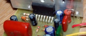
Here is a clear example that a burnt resistor has left marks on neighboring resistors; there is a possibility that they are also damaged:
The resistor has turned black from the high temperature, not only traces of burning are visible on the neighboring elements, but also traces of overheated paint, its color has changed, and part of the conductive resistive layer could be damaged.
The video below clearly shows how to check a resistor with a multimeter:
Determining the resistor value
For Soviet resistance denominations, the denomination was indicated alphanumerically. In modern output resistors, the value is encrypted with color stripes. To replace the resistance after checking for serviceability, you need to decipher the markings of the burnt one.
There are a lot of free Android applications for identifying markings by color stripes. Previously, tables and special devices were used.
You can make a cheat sheet like this to check:
Cut out colored circles, pierce them in the center and connect them, the largest one to the back, the smallest one to the front. By combining the circles, you determine the resistance of the element.
By the way, modern ceramic resistors also use explicit markings indicating the resistance and power of the element.
If we are talking about SMD elements, everything is quite simple here. Let's say the marking is “123”:
12 * 10 3 = 12000 Ohm = 12 kOhm
There are also other markings of 1, 2, 3 and 4 characters.
If a part is burned so that the markings are not visible at all, you should try rubbing it with your finger or an eraser; if this does not help, we have three options:
- Look on the electrical circuit diagram.
- Some circuits have several identical circuits; in this case, you can check the rating of the part on the adjacent stage. Example: pull-up resistors on buttons on microcontrollers, limiting resistances of indicators.
- Measure the resistance of the surviving section.
There is nothing to add about the first two methods, let's find out how to check the resistance of a burnt resistor.
Let's start by cleaning the part's coating. After this, turn on the resistance measurement mode on the multimeter, it is usually labeled “Ohm” or “Ω”.
If you are lucky and the area directly next to the output burns out, simply measure the resistance at the ends of the resistive layer.
In the example shown in the photo, you can measure the resistance of the resistive layer or determine it by the color of the marking stripes; here they are not covered with soot - a fortunate coincidence.
Well, if you are unlucky and part of the resistive layer has burned out, all that remains is to measure a small area and multiply the result by the number of such areas along the entire length of the resistance. Those. in the picture you see that the probes are connected to a piece equal to 1/5 of the total length:
Then the total resistance is:
This check allows you to get a result close to the real value of the burnt element. This method is described in detail in the video:
What kind of radio element is a resistor and its main signs of performance?
A resistor can be called the simplest radio element that can be found in nature. Indeed, all its functions are reduced only to reducing the potential, that is, it is a current and then voltage limiter. Since these quantities depend on each other. A resistor can be compared to a narrow section of pipe in a pipeline, when initially one volume of liquid passed through it, and then a much smaller volume began to pass through. Only here the current acts as a liquid, that is, the directed movement of electrons. How can you limit the movement of current?
In most cases, the resistor is designed as follows. This is a thin nichrome wire wound on a ceramic frame, or ceramics in which conductive particles are included. In the first case, the thinner the wire, the greater the resistance. Secondly, the fewer conductive particles, the higher the resistance of the resistor. One more fact should be noted here: if our pressure is too strong, then instead of limiting it, it will rupture the pipeline. The same is the case with a resistor. If it overheats and the conductor is damaged, the resistor will be damaged. The ability to contain overheating relates to the power of the resistor. As a result, a resistor has two main properties. The first is to provide resistance, which is measured in Ohms. Second, withstand a certain current. Since current flows per unit time, it is essentially the ability to dissipate heat over the same specific period of time. And we all know that if something does some work per unit of time, even if it just dissipates heat, then this characteristic is called nothing more than power
It is this resistance of the resistor to burnout, so to speak, that will be described by its power. If the resistor fails to cope with the tasks assigned to it, it does not matter for what reasons, be it a miscalculation by the designer or abnormal current deviations in the circuit. In this case it will simply burn out
At first it will overheat, the beautiful paint with stripes or letters will peel off, and then it will completely turn black and become unlike itself. Like what is shown in our picture.
This is precisely what can be considered the first indirect reason for checking and replacing the resistor. However, before checking the resistor, you need to know what we will be checking, that is, know what value it had. More on this in the paragraph below.
What is clearance and how important is it?
This value shows the possible deviation of a given series from the specified nominal value. A correctly calculated circuit must take this indicator into account, or appropriate adjustments are made after assembly. As you understand, our friends from the Celestial Empire do not bother themselves with this, which has a positive effect on the cost of their goods.
The result of such a policy was shown in Figure 4; the part works for some time until the limit of its safety margin is reached.
- We make a decision by comparing the readings of the multimeter with the nominal value; if the discrepancy goes beyond the error limits, the part definitely needs to be replaced.
Types of multimeters and the principle of their design
The most common types of multimeters are analog and digital. Let's look at how they are designed and work below.
Analog
These are old-style testers that look like boxes with a glazed arc-shaped scale and a spring-loaded pointer. Often there is a mirror arc on the scale so that when you look at the arrow you can align the arrow with its reflection. This way, when measuring, you are looking exactly perpendicular to the scale, rather than at an angle, and it will be more difficult for you to make a mistake. The measuring panel has many parallel arc scales for different types of measurements:
Analog multimeter.
One of the main advantages of an analog multimeter is its low price and measurement accuracy that is quite sufficient for everyday purposes. Moreover, most analog multimeters have a built-in special resistor to adjust the position of the arrow exactly to “0”. For adjustment, a resistor head is used, similar to a screw slot, located below the measuring scale approximately at the point where the arrow is attached.
Digital
These multimeters are more modern and look like oblong black boxes with a large liquid crystal display for digital readings. These devices got their name because the analog signals entering the device are converted into digital form in an analog-to-digital converter (ADC). Such devices are more expensive than analog ones, but their size and weight are somewhat smaller, and it is more convenient and faster to work with them.
Some models are well suited for working in complete darkness due to the ability to illuminate the indicator panel (and electricians often have to work in dark rooms). You simply press a button and the panel lights up. In addition, you can find a model with the ability to record the readings taken into the device’s memory and subsequently transfer this data to a computer for further analysis. To do this, just press a special button. Typically, digital devices are used by professional electricians, electronics engineers and engineers.
Digital multimeter.
The measurement kit includes two wires with terminals and pointed probes:
- one black wire – “minus”, “ground”, “com” (common);
- the second red wire is positive or “measuring”.
The black probe is usually applied to the body of the electrical appliance (common busbar) or attached with a special clip - an “alligator clip”. The red probe is most often taken in the right hand and applied to different places in the circuit. The probes included in the digital multimeter are the same as those in the analog multimeter. Often the sockets are color-coded - red and black frames, so as not to accidentally confuse which probe is inserted where.
Sometimes the multimeter is a built-in part of another device, such as a digital clamp meter. Due to the need to be large, such devices have a large amount of free space in their housing, where the multimeter is built in.
Preparing a multimeter for measurements: what settings to set
Before measurements, the device is prepared for operation. To do this, it is turned on and the ends of the probes are short-circuited with each other. If zeros appear on the display, then the device is working properly and there is no break in the circuit. The display may show fractions of an Ohm rather than zeros.
Preparing the device for testing
When the probes are open, a working multimeter displays the number 1 and the measurement range. The cable cords are connected in accordance with the mode that you need - “Dialing” or “Measurement”.
How to ring a resistor
The “Continuity” mode (not available in all testers) is used to make sure that there is no short circuit in the circuits running through or parallel to the resistor. To install it, turn the knob towards the diode icon. If there is a current-carrying circuit between the probe installation points, then a sound signal is generated through the speaker.
This mode is used only for resistors whose value does not exceed 70 Ohms. It makes no sense to use it for parts with a high rating, since the signal is so weak that it may not be heard.
Measuring own inductance, resistor capacitance
Let us first assume that we have the necessary measurement tools. Then the procedure is established:
- We take the first frequency generator. For example, 15 MHz. A variable capacitance (a whole battery) is connected in parallel with the resistance. The values of the capacitors (the parasitic resistor selected by the user) are added together. The total capacitance is formed by a variable, its own (resistor). A parallel oscillatory circuit is formed.
- We turn on a purely active load in series. Another resistor of a similar value. The completed measure forms a voltage divider. We will try to achieve resonance with further regulation. To register the fact that the circuit has reached a given state, it is necessary to assemble a divisor.
- By selecting the nominal value of the variable capacitance, we achieve system resonance. We turn it back and forth and use a tester to measure the voltage of the oscillatory circuit by inserting the attachment described above. The minimum potential difference indicates the resonance point.
- Let's remember the nominal value of the variable capacitance. Traditionally, there is a regulator knob, but there is no scale. It is impossible to view the readings. Disassemble the circuit, saving the settings, measure the nominal value. The easiest way is to use a multimeter equipped with an appropriate scale (F). Otherwise, a number of indirect measurements will be required. A separate topic.
- We repeat the experiment, taking a different frequency. Obtaining a noticeable difference in the recorded readings. The magnitude of the discrepancy characterizes the resulting nominal value of the variable capacitance. The numbers must be different (ensuring minimal error). Tried, failed? The conclusion suggests itself: we will neglect the resistor’s own capacitance under the specified conditions (very small). We find the inductance using the typical circuit resonance formula: ω2 = 1 / LC.
- We begin the calculation, guided by the following considerations: the square of the circular frequency of the generator (radio frequency multiplied by two Pi numbers) is inversely proportional to the product of the capacitor’s own inductance and the sum of the parasitic, variable capacitances. By measuring two different frequencies (let's say 15.7 MHz), you can get two results. The ratings of variable capacitances are important. If we divide the squares of circular frequencies using the formula, we get: the square of the ratio of ordinary frequencies correlates only with the quotient of the capacitances, the inductances will be reduced.
This is what it looks like:
(f1/f2)2 = (C + C2) / (C + C1); f1, f2—experiment frequencies (Hz), C—resistor’s own capacitance; C1, C2 are variable capacitances, respectively, of the first and second frequencies of the experiment. Using the formula, take the trouble to find your own capacitance, following the beaten path, calculate the inductance of the resistor
Please note: it is important to find the minimum voltage. The way to do what is planned is a separate topic of conversation
How to check a resistor without desoldering: visual check
The process of checking a resistor for functionality directly on the board without completely desoldering is a rather labor-intensive task, so you can first determine the burnt part visually. First of all, inspect the case for damage and chips, and the reliability of fastening the terminals.
Malfunctions are indicated by:
- Darkening of the body. A burnt resistor has a darkened surface - completely or partially in the form of rings. Slight darkening does not indicate a malfunction, but only overheating, which did not lead to complete failure of the part.
- The appearance of a characteristic odor.
- Erasing markings.
- Presence of burnt tracks on the board
If conditions allow, the faulty resistor is soldered off, and a new one with the same rating is soldered in its place.
Attention! Inspection does not guarantee an accurate determination of serviceability; the resistor may look like new even with a broken contact
Visual inspection
Violation of the normal operating mode causes overheating of the part, therefore, in most cases, the problematic element can be identified by its appearance. This can be either a change in the color of the case or its complete or partial destruction. In such cases, it is necessary to replace the burnt element.
Figure 4. A clear example of how a resistor can burn out
Pay attention to the photo above, the component clearly needs to be replaced, while the neighboring parts “2” and “3” may be working, but they need to be checked.