Until now, the choke for lamps has been an indispensable component of a fluorescent lamp (FL), released by the English company General Electric in 1934. She created the first hot cathode tubes, which used a positive discharge in a column in a low-pressure mercury atmosphere to generate short-wave UV radiation. The latter stimulated a fluorescent powder coating on the inner surface of the discharge tube. Although the design still lacked many modern features, it was General Electric that pioneered the fluorescent lamp market.
Choke for light bulbs
The popularity of fluorescent lamps is confirmed by the fact that today they produce more light on the planet than any other source. Peak production was reached by 1970. According to modern estimates, today they account for about 80% of the world's artificial lighting.
Fluorescent lighting
Fluorescent lighting offers a low system cost and a very long service life. It is fully dimmable and easy to use, and in addition achieves high luminous efficiency. The large tube area is well suited for efficient and glare-free illumination of large spaces.
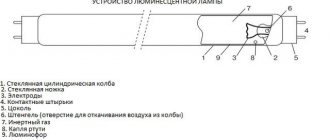
A fluorescent lamp uses electricity to enable mercury gas to emit ultraviolet (UV) light. When this light, which is invisible to the naked eye, interacts with the phosphor powder coating inside the tube, it begins to glow and emit a bright light. In order to control the transmitted electricity, a choke is used, or in Western terminology, a ballast choke or control mechanism. It is a small device connected to the light source's electrical circuit that limits the amount of current passing through it.
Choke for light bulbs
Since the household voltage is higher than what is needed to operate the luminaire, the inductor initially gives the source a voltage surge to start, and then only maintains the minimum amount for safe operation.
The process that occurs inside the fluorescent light involves mercury gas molecules heated by electricity. Without a choke to control this process, a lot of current would flow into the lamp, which would destroy it.
Fluorescent lamps use two types of ballasts:
- Magnetic ones, which are outdated and are no longer used in new lamp models today. Their work is based on the principles of electromagnetism, when an electric current passes through a wire, it generates a magnetic force around itself. The ballast contains a coil of copper wire. The magnetic field created by the wire traps most of the current. This amount may vary depending on the thickness and length of the copper wire.
- An electronic choke for fluorescent lamps uses more complex circuits and components and can more accurately control the current passing through the fluorescent lamps. Compared to their magnetic counterparts, they are smaller, lighter, more efficient and, by delivering energy at a much higher frequency, cause virtually no flickering or buzzing.
Important! Magnetic ballasts cannot function without the help of a starter. This small cylindrical element is located behind the lamp and is filled with gas, which, when heated, allows the light to ignite.
You might be interested in Halogen lamps for lighting: main types
Kinds
Chokes are divided into the same types as the lamps connected to them. If you connect a lamp to a choke that does not meet its specifications, this will most likely lead to failure of any of the elements used in the connection system. There are the following types of chokes, divided depending on power:
- choke with a power of 9 W - for energy-saving lamps;
- 11 W - for miniature lamps;
- 15 W - for table lamps;
- 18 W - for office lamps;
- 36 W - for small fluorescent lamps;
- 58 W - for ceiling lamps;
- 65 W - for multi-lamp ceiling lamps;
- 80 W - for large fluorescent lamps.
Characteristics
Basic functions of ballasts: provides the process of heating the cathodes to start the electron emission process, creates a starting discharge voltage and subsequent limitation of the operating current. In AC mode, it provides a phase shift (cos f) between I and U, called power factor. This value is indicated in the passport and ballast markings. Active power is calculated by the relation: P = U x I x cosf, it is obvious that low cos f increases the use of reactive energy.
Ballast marking
In connection with this, ballasts are grouped by power level:
- C—low indicator;
- B—super low;
- D is the average absorption possibility.
Classification by noise level:
- C - very low noise effect;
- A - particularly low indicator;
- P - reduced noise;
- N is normal.
The technical characteristics of the ballast must correspond to the power indicators of the lamp, otherwise it will not work.
Fluorescent lamps require the installation of chokes of various powers:
- W up to 15.0 W - small table lamps;
- 16.0 W to 36.0 W - ceiling and wall household lighting devices;
- 37.0 W to 80.0 W - powerful industrial lighting systems with several single points of light.
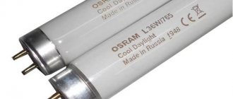
In Russia, fluorescent lamps and components are produced in fairly large quantities - from a million lamps per year. Production is organized at the following enterprises: LISMA-VNIIS named after. Lodygina, “Photon”, Saransk Precision Instruments Plant, . Among Western manufacturers, the Greek company Schwabe Hellas and the Finnish Helvar are popular. It is believed that it is better to purchase ballasts and starters from well-known brands such as Navigator or Luxe.
Specifications
The technical features of chokes that you should definitely pay attention to when choosing a light source are the following:
- Purpose. In a luminescent device, the inductor coil creates the necessary impulse so that metal vapors can burn in the device, and it also maintains the required power value during operation of the device.
- Power. The main technical parameter of the limiter is its power value. The performance of all other parameters and the lamp as a whole depends on it. Based on power indicators, these parameters will be different for each lamp limiter. According to the power level, limiters are divided into three large categories: B, C, and D. The name of the limiters depends on which category they belong to.
- Self-induction coefficient. Due to the inductance of the inductor, the power of electricity that falls on the conductive contacts of the lamp.
Self-induction coefficient.
How does it work
Initially, an alternating voltage is supplied, which, after passing through the inductor, reaches the lamp. Since the power is transmitted through the ballast, which is an inductor, it limits the current and prevents the lamp from shorting. Next, the current passes through the filaments and heats them, as well as the gases present in the tube.
Operation of fluorescent lamps
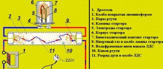
The discharge tube is filled with argon gas and has a phosphor coating inside and also contains a small amount of mercury. The current then flows to the starter, which has a bimetallic strip inside it that expands when heated and completes the circuit, bypassing the lamp and creating a short circuit. When the circuit is closed, the voltage drops to zero. After the bimetallic strip cools, it returns to its original position, opening the circuit. Since the ballast contains an inductor and its own magnetic field.
When the circuit is opened, the magnetic field is destroyed and this creates an inductive shock with a surge of high voltage passing through the filament, creating an arc to excite photons in the argon gas environment. Their emission causes the emission of ultraviolet light, which, passing through the phosphor coating of the lamp, is converted into visible light.
Operating principle and functions of the throttle
It is recommended to start getting acquainted with the throttle by considering its main functions. Everyone knows that fluorescent lamps contain a ballast that absorbs excess power in the electrical circuit. In a lamp with a power of about 40 W, the choke accounts for approximately 6 W or 15%.
The main functions of this device are the following:
- Preheating of cathodes and preparing them for further electron emission.
- Providing the required voltage to create a starting discharge.
- Limiting the current passing through the electrical circuit of the device after start.
When using alternating current as power, a choke is used to provide a phase shift or lag between voltage and current. This value is indicated in the device labeling as cos ϕ, also called power factor. The power of the fluorescent lamp and the technical characteristics of the choke must match each other, otherwise the lamp will fail very quickly.
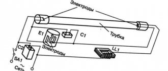
The throttle operates in conjunction with the starter according to the following scheme:
- At the beginning, the voltage supplied to the lamp goes to the starter. The design of this element consists of a capacitor and a cylinder filled with an inert gas, inside of which there are bimetallic contacts.
- The action of voltage causes ionization of the gas, as a result, current begins to flow through the throttle circuit. The contacts and gas are heated, after which the current increases to 0.5 A. After this, the cathodes are heated with the simultaneous release of electrons. Under their influence, the mercury vapor located in the lamp tube is heated.
- At the moment the contacts close, ionization is completed, the temperature in the starter drops and the contacts open.
- Self-induction occurs in the choke, which, together with the amplitude oscillations of the network, breaks through the gas filling of the lamp. After this, the current again begins to flow through the cathode and the electrical circuit of the inductor.
Throttle purpose
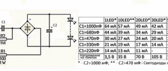
The circuit diagrams of electronic ballasts are different. But they all support the actual generic block diagram:
- First, a series resistor is connected. It is connected to limit overload and short circuit current. Some electronic ballasts use a fuse instead of a series resistor. This resistor has a very low value of up to 22 ohms.
- Then an EMI filter circuit is connected, which consists of one series inductor and one parallel capacitor.
- A rectifier circuit is then used to convert AC to DC. The bridge rectifier circuit consists of four PN diodes.
- A capacitor is connected in parallel to filter the DC current coming from the rectifier circuit.
You may be interested in Features of illumination calculation
An inverter circuit using two transistors is used. These transistors produce high frequency alternating current and a step up transformer. With electronic ballast frequency from 20.0 kHz to 8.00 kHz. Typically, a transistor produces a square wave current signal. The step-up transformer increases the voltage level to 1000.0 V. At the initial moment and after the incandescent light bulb lights up, the voltage across it decreases to 230 V. Thus, the main purpose of the inductor in a fluorescent lamp is to restrain the current when the lighting device is operating.
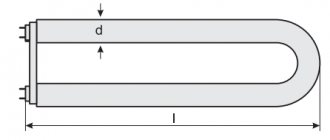
Design
Structurally, it is made of an inductive coil wound on a ferrimagnetic core, similar to a transformer, but with one winding made of copper enamel wire.
Typical throttle structure:
- Insulated coated wire;
- a core of ferrite construction that provides inductance;
- filling compound - a non-flammable substance to additionally ensure interturn insulation;
- housing made of heat-resistant polymers to accommodate functional units.
Coil
The choke in the LL circuit must make a jump in order for the self-induction emf of the coil to occur according to Lenz’s rule. To increase these properties, the wire is wound onto the core, thereby increasing the electromagnetic flux.
Thus, according to the design, ballast is an ordinary coil operating like an electric transformer.
Throttle coil
Note! Before use, they need to be accurately calculated to ensure the lamps work. Especially at the moment the glow starts, when a sufficiently high voltage discharge is required to break through the gaseous environment.
After which the ballast will take on the functions of a damping device. Since in order for the LL to glow, large current parameters are not required, and therefore this class of lamps has increased efficiency.
Ballast core
The inductance of the fluorescent lamp choke is provided by the core, so it is made of plates with ferromagnetic properties, insulated from each other to prevent Foucault currents from creating unacceptable interference in operation. It serves as a powerful functional barrier, both when the input voltage decreases and when it rises.
Core
The design refers to low-frequency circuits. Alternating current in household electrical networks has a wide range of fluctuations: from 1.0 to a billion Hz and above and is grouped into the following gradations:
- Audio low frequencies with a range from 20.1 Hz to 20.1 kHz.
- Ultrasonic from 20.1 kHz to 100.1 kHz.
- Ultra high above 100.1 kHz.
Additional Information . The core is present only in low-frequency chokes; in high-frequency versions, cores are not installed. To wind copper wire, use plastic frames or ordinary resistors. In this case, the transformer is made in the form of sectional, multilayer winding.
Verification methods
It is advisable to use instruments to diagnose the condition, but if they are not available, the assessment of the condition can be done without them.
Without tester
You can check the choke of a fluorescent lamp without a tester and other devices (at least an indicator screwdriver). But the reliability of these methods is limited.
- First of all, this is the behavior of the lamp . If, when voltage is applied, it flashes, but does not reach a steady glow, then there is a reason to check the inductor (although there may be other reasons, including a malfunction of the lamp itself). If there is a break in the coil, there will be no blinking - the circuit will not show any signs of life at all.
- Visual inspection . If there is blackening, swelling, or traces of local overheating on the throttle body - all this is a reason to doubt the serviceability of the device. It must be replaced or diagnosed using instruments.
- Installation in a known-good lamp instead of a standard one . If after replacement the lighting fixture stops working, then the problem is in the throttle. Or, conversely, install a known-good choke into a non-working lamp. If the problem is resolved, then the problem has been found.
You can assemble a stand for testing ballast elements. This makes sense if you have to maintain the lighting system of a building, office, workshop, etc., built using fluorescent lamps. As a stand, you can take a ready-made lamp and replace its standard parts with tested ones, or you can assemble a simple circuit. It uses a regular 220 volt incandescent lamp.
Stand for testing ballasts.
To check the choke of a fluorescent lamp, the properties of the inductive reactance of the choke coil are used. Various situations are possible:
- the lamp is lit at full intensity - the inductor is working, its reactance limits the current in the series circuit;
- the lamp burns at full brightness - there is an interturn short circuit, the inductance of the coil is small, the reactive component of the resistance is close to zero;
- The lamp does not light - there is a break inside the throttle.
It will not be possible to check elements of electronic ballasts (EPG) on such a stand. It works on a different principle.
If a choke with a breakdown on the body is tested, then when power is applied, mains voltage will be present on its body. The ballast elements must be connected when the voltage is off. Take precautions when serving food.
Using a multimeter
The multimeter provides greater opportunities for checking ballast elements and the reliability of such testing is higher.
On a cliff
To check for an open circuit, a multimeter in resistance measurement mode (or audio testing) must be connected to the ballast terminals. If the device is working properly, the tester will show a resistance of several tens of ohms (depending on the type of inductor, for most common models it is about 55..60 ohms).
Check for a break.
If the internal circuit is open, the meter will show infinite resistance.
You can also check the ballast for breakage using an indicator screwdriver. This can be done without removing the device from the lamp, but only by removing the cover and applying 220 volt power (turning on the light switch).
Check for a break with an indicator screwdriver.
It is necessary to check the presence of voltage at the inductor input, and then at the output. If power comes to the ballast input, but there is no power at the output, it means there is a break in the inductor.
How to choose
The passport documentation for the choke indicates which types and configurations of lamps are designed to work with it. To make the right choice, you need to pay attention to the following data:
- Checklist of LL throttle selection parameters.
- Start type - instant or programmed.
- The normal ballast factor (0.77 to 1.1) is the default value for most lamps.
- Input voltage - 120/230/380V.
- The minimum initial temperature is from −17C to 20C.
- The parallel scheme is the norm. This allows other lamps to remain lit even if one lamp in the fixture goes out.
- Anti-stratification control - unwanted bright and dim areas that can form a standing wave structure along the entire length of the lamp. Streaks are more likely to occur when the lamp is operated at low temperatures.
- Sound Rating: A ballast rated "A" will hum quietly; A ballast rated "D" will produce a pronounced noise.
- Manufacturer's warranty.
You might be interested in this: Characteristics of different types of lamps
How to connect a choke
Installing a fluorescent choke is not difficult, but, as always, when working with electrical circuits, it is better to entrust it to a qualified specialist if the user does not have the appropriate electrical safety clearance group.
Algorithm for installing the throttle on the LL:
- When installing a fluorescent lighting device, first turn off the power supply.
- Remove the diffuser plate covering the lamp and remove the lamp itself.
- When gaining access to the throttle, remove the cover from it and disconnect all the wires. Before doing this, it is recommended to make sure that the device is not powered using a voltage tester.
- After purchasing the necessary ballast, the wires are stripped and connected according to the specified diagram.
- Turn on the power only when all the above steps have been completed in reverse order and the ballast is completely installed.
Note! According to European regulations, old chokes are disposed of because they contain toxins that are harmful to the environment.
How to replace
Recently, very often such an operation is caused by the need to replace magnetic chokes with electronic ones. This process is quite simple and straightforward, but must also be performed by specialist electricians. The process of replacing ballast from magnetic to electronic:
- Turn off power to the device.
- Open the lamp, remove the bulb and ballast casing.
- Using wire cutters, cut the power (brown) and neutral (blue) wires going into the device.
- Cover the wires with wire nuts.
- Use wire cutters to cut off the wires and remove the magnetic ballast.
- Attach the electronic ballast to the place where the magnetic one was.
- Connect the power and neutral wires to the corresponding ballast wires.
- Secure the wires with wire nuts.
- Return the lamp bulb and throttle housing back.
- Turn on the power to the lamp.
Properly installed and functioning electric lighting ballasts should last a long time, providing safe, well-regulated current to lighting fixtures without annoying flickering or humming.
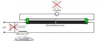
Daylighting scheme
The choke, although it plays an important role in the installation of LL today, is no longer indispensable; its place has been taken by an electronic ballast (electronic ballast). Property owners planning to install such lighting should take into account that on July 1, 2021, the use of tubular LLs, as well as mercury lamps, is prohibited in Russia, and from the beginning of 2021, fluorescent and sodium lamps will be prohibited.