Why should a light switch break a phase, and not a zero?
At first glance, there is no difference, both circuits work the same way, because even if the zero is broken by the switch, the light will go out in the same way as with a phase break.
To better understand this, let's, for clarity, look at a switch connection diagram in which a neutral conductor (zero) is connected to it.
As you can see, with such a circuit for connecting the switch, there is always voltage on the lamp, this is the main drawback that can cause serious problems and inconvenience in the operation and maintenance of light sources.
First of all, the main danger of this connection method is that you can be “shocked”, for example, when replacing lamps, when you accidentally touch the conductive contacts.
In addition, if the insulation of the supply cable is broken or the electrical connection inside the lamp is damaged, the phase conductor may short-circuit to the housing. And then, with a simple touch of a chandelier or sconce, you yourself will become a conductor, part of the electrical network, you will feel a serious electric discharge, and, under certain conditions, electric shock can even be fatal.
This becomes especially relevant because for lighting groups, in the same PUE, it is allowed not to install differential protection, for example, an RCD, so you will learn about the voltage on the housing only when you feel the discharge, while the lamp may not even be turned on.
Another less dangerous, but no less unpleasant problem is the flickering of lamps when the lights are off. Modern energy-efficient lamps - energy-saving (fluorescent) or LED, can respond to even minor fluctuations in the electrical network; even ultra-low currents can trigger them. Therefore, even when the light switch is turned off, such lamps can flicker, and this reduces both the life of the lamps and simply irritates many.
Therefore, in order to avoid these and some other problems, it is correct to make sure that the switch breaks the phase and not the zero.
Unfortunately, most often, people wonder whether phase or zero should be in the switch in the case when they are already faced with incorrect wiring, having zero in the switch and all the problems described above. What to do in this case?
Why are there two phases in the socket?
one phase enters the apartment through the meter and machines
. The socket must have one phase and zero, and in the above situation, the indicator indicates the presence of the same phase in both sockets of the socket.
The most likely cause of the malfunction in this case is damage (break) of the neutral wire going to the socket during the process of drilling the wall.
The presence of a phase where zero should be is due to the fact that it passes through a load - a constantly on light bulb or some other electrical appliance.
As a rule, all neutral wires in a house or apartment are closed to the neutral bus of the electrical panel, the phase will appear in the socket. This is very easy to check - you just need to turn off all electrical appliances in the apartment.
Why, after disconnecting all electrical appliances from the network, are there still two phases in the outlet?
So, you have turned off all electrical consumers from the sockets, turned off all the switches, but they are still present. The reason for this may be the following.
During the drilling process, the zero was broken by the drill and short-circuited. The same situation can occur during a short circuit, when the braiding of the wires melts and the conductors short-circuit.
In any case, it is necessary to turn off all electrical appliances, then inspect the drilling site and eliminate the malfunction.
The reason for the appearance of two phases in the outlet
may be the most trivial - this can happen simply because a fuse (plug) has blown or the circuit breaker on the electrical panel has turned off.
Is it possible that there really are two different phases
? The author of this article once encountered this. At the same time, the TV, refrigerator and several light bulbs burned out, since the voltage between different phases was really 380, not 220 volts.
The reason was the short circuit of one of the three phases running along the overhead power line to the neutral wire (this happened in the private sector).
In order to have reliable information about the presence of phases and voltage in the network of your apartment, one phase indicator is not enough. To measure voltage, it is better to purchase a combined device - a multimeter that measures voltage, current and resistance.
For home needs, the cheapest one is suitable.
In any case, we must not forget about safety measures, since even through a load you can get a very noticeable electric shock.
Similar materials on the site:
So I realized that the house was brick. 2 groups of apartments are mixed (lighting and sockets).
Absolutely right. Each group consists of two large twists in a box, wound with pliers. No soldering, no welding, no nuts.
We set the switches in these rooms to the OFF position. With an indicator (with neon) what do we see on the ceiling? If the indicator shows PHASE for this group, then ZERO is broken. Also check in another room for this group.
Both rooms are absolutely the same. Everywhere, when the switch on the socket is open, there are visually two phases on the socket.
But in no case to the BATTERY!!!
So this is a short-term test, everyone seems to be alive, and the battery saved me a lot of time on extending the probe from the multimeter.
ald, if you want to have a phase break on the switch, first post a photo of the connection at the meter and the machines on the staircase
I described in the first post that there the phase is parallelized by a comb into 3 Soviet machine guns (something like AB-25 visually), well, and 2 zeros for noodles. I can take a photo, but the connection is not visible, since the Mercury meter is closed and sealed and everything goes through the back, where I can’t put my nose, even if I wanted to.
It is possible that the wires were transferred to this. shield (phase damage). A megohmmeter will show the truth.
At the input of the machines, I clearly see the phase with a “screwdriver”.
Is there anywhere else on this line where the light is on (current consumption)? In general, turn off everything you can on the line and leave only this switch on, then look at the phase or zero in the cartridge. I am sure you will find everything, and there will also be an opportunity to understand.
There was only a router on this line, which I turned off.
It’s better to deal with all the wiring, and not just one line, you never know what they could have piled up in 30 years...
On the first line (which is the kitchen, corridor, bathrooms and room) I have already installed automatic machines (with a reduction towards the consumer: 6A light, 10.16 sockets (for a vacuum cleaner) and even 6A for a refrigerator), there is no such problem there, and not was. And I needed a guarantee that there was at least some kind of protection while I was away.
But I didn’t even touch or look at the second line, which I’m writing about now, for garlic, but now I understand that the twists need to be urgently unwound and temporarily scattered among the machines. The third line, about which I wrote that it was there but not connected, I brought it out of the panel with copper, but did not connect it (they promised to change the staircase machines and the package, I even prepared 20 amperes, but the promise remained a promise). We still need to run after our electricians. I wanted to change all three staircase machines myself, but the package operator did not turn off the phase the first time, and I didn’t try again.
When only one switch is turned on on the line (and per phase), then everything is OK in the cartridge.
I'll try in the box, when I unwind it, to give the switch a guaranteed phase. I initially suspected that the zero was set, and somehow encountered this, but in that case there was a faint glow on the contact, but not a good, bold 220. And the behavior of the switch confused me, although everything is logical if you think with your head).
In general, I advise you to ignore this and carry out new, normal wiring as it should be for you.
Yes, I will do that, but it’s a matter of time, and the “two-phase issue” has arisen right now, when there is no way to reinstall the cable. But there are a lot of automatic machines, ouzo and other devices =).
In normal situations, when checking the operation of the socket using a voltage indicator, the phase wire causes the light bulb to glow, and with the neutral wire the light bulb will not light up. However, a situation arises when the socket is not functioning, and the indicator detects two phases in the socket. Not everyone knows what to do in such cases. Typically, this happens in buildings where old or poorly executed wiring is installed with violations of installation rules. What are the reasons for this phenomenon?
Replacing a light switch in an apartment - simple instructions for complex work for beginners
Electrical accessories
07.07.2017
6.7 thousand
4.5 thousand
5 minutes.
Modern light switches are made of high quality materials, but over time even they fail. This leads us to the need to replace electrical equipment.
This can happen anywhere: in the office, at work or at home. However, you do not need to resort to the help of professional specialists if you master the technique of replacing switches yourself.
This is not to say that the work is very simple, but with due diligence and care, anyone can cope with it.
Replacing a light switch in an apartment is a relatively quick procedure that does not require any additional tools or equipment
However, you must act as carefully and carefully as possible, since you have to deal with electricity. Wrong actions can lead to very disastrous consequences:
- Fire of wiring in the distribution panel and walls;
- Failure of lamps and other household appliances connected to the network;
- Short circuit;
- The saddest development of events is electric shock.
In this regard, before starting work, it is imperative to purchase protective gloves, preferably made of rubber, and strictly follow all the requirements and rules of electrical safety.
To avoid mistakes during operation, it is recommended to spend some time studying the design features of electrical equipment, and also remember the connection diagrams in the electrical wiring circuit.
In some cases, you can even take a photo with your phone so that there are no problems later after replacing a broken device.
Replace switches yourself without using protective equipment, only if you are confident in your actions!
Due to the fact that light switches are used almost constantly, especially in the winter, a huge number of different models have been developed that differ in appearance, design features, and functionality. First of all, there are two groups of switches depending on the mounting to the wall:
- 1. Hidden wiring - a special metal or plastic socket box is used, installed in a recess in the wall. This is where the equipment is installed.
- 2. Open wiring - in this case, you will need surface-mounted switches, which are used in panel board products made of wood. The cable is routed outside, so it has to be hidden in special cable channels so as not to be accidentally damaged during everyday activities.
If we talk about the design of the terminals with which the device is attached to the wiring, then there are also two main groups. The first includes screw terminals - these elements are designed to secure the stripped ends of the wire located between the plates.
If you use aluminum wires together with brass plates, a lot of resistance is created, which causes serious overheating of the entire equipment. To avoid this, it is necessary to constantly tighten the screws, which will ensure high-quality contact between the elements.
At the same time, copper is not subject to such temperature changes, so wiring made from copper wires does not overheat.
Procedure for replacing double switches
Naturally, changing wiring to copper seems to be a rather complicated process. It is much easier to use clamp terminals, which are equipped with a special spring mechanism.
Thanks to this, the brass plate is constantly under enormous pressure, resulting in reliable and high-quality contact.
The possibility of fire is minimal, while preventive tightening of the screws will no longer be necessary.
Based on the number of buttons, light switches are:
- 1. Single-button – work with one light source or group of lamps. When pressed, all lighting elements connected to this switch are turned on at once.
- 2. Devices with two or more buttons - with the help of such devices you can turn on individual lamps on a chandelier. Very convenient, especially if the lamp is equipped with a large number of lamps. In this case, you can turn on only a few lamps so as not to waste a large amount of electrical energy.
Speaking about the types of switches, it is impossible not to note modern expensive designs that are becoming increasingly in demand:
- With a dimmer - a rotating element that allows you to smoothly increase or decrease the brightness of the light;
- Touch – responsive to the palm placed in close proximity to the equipment;
Advantages and disadvantages
Advantages of this cartridge:
- ease of disassembly and assembly
- time-tested reliability
- contact pads are fixed with screws
Firstly, if necessary (burnout, melting), they can be replaced. Or simply tighten it when the contacts loosen and the connection heats up.
By the way, these screws need to be tightened initially, even before directly connecting the wires. This will extend the life of the socket and light bulb significantly.
In 90% of cases, the light bulb stops shining because the central contact heats up and its plate-shaped area begins to bend, gradually moving away from the lamp base.
Flaws:
- inconvenient connection to screw terminals
To ensure good contact, you will have to unscrew them entirely from their seat.
Moreover, if you have a non-Wera screwdriver with a bunch of additional “chips,” then this screw often falls out and rolls into the most inappropriate places.
Although experienced electricians do without completely unscrewing the screws and bending the neat rings on the copper conductors. The entire connection is made much easier.
The veins are stripped a little more than usual (2-3 centimeters), and the screws are only loosened. Next, place the vein under the washer with the screw and make a turn strictly in the direction of tightening the thread.
This is necessary so that when tightening the screw, the ring does not unbend, but rather tightens even better.
After this, bite off all the excess protruding behind the bolt with side cutters. You should end up with some kind of half ring.
All that remains is to squeeze it with platypuses to a full ring.
It is not yet possible to tighten such a connection. It should “play” in its seat.
Take the second wire and do the same procedure with it. Only then can the screws be tightened as far as possible. As a result of such a connection, there is no need to unscrew anything, make some rings in advance, guessing the diameter of the bolts.
All this is adjusted directly on the cartridge itself. Saving time and labor costs is obvious.
The only disadvantage of this method is that the wire consumption will be a couple of centimeters more than usual.
Installation of a two-button light switch and connecting wires
There is nothing complicated in the connection diagram and in the process of installation, installation and connection of wires to the switch contacts. First of all, the switch needs to be disassembled. To do this, remove the keys themselves. If you can’t do this manually by simply pulling them towards you, use an ordinary screwdriver, prying the keys off from the side.
Next comes the insulating decorative backing; it can either be snap-on or screwed on. Remove this frame.
As a result, what you have in your hands is the body itself with the fastenings on the sides and the internal contact part. The main task is to supply voltage from the phase conductor to the common contact. Further, when two keys are closed, this phase will diverge into one or the other lighting circuit.
To find the central contact, look at the marking, since it may not always be located alone and in the center.
What to do if you don’t understand the inscriptions or they are erased and painted over? Then you need to use a contact screwdriver with a battery-powered tester with a continuity test function. Insert any metal object (nail, screw) into the supposed common contact. You wrap your fingers around it and touch the other two contacts with a screwdriver.
When you press the keys one by one, that is, turn on one - check, then turn off the first and turn on the second - check, the screwdriver LED should light up each time. If this does not happen, then this is not a common contact.
When you have dealt with the contact part of the switch, take the three-core cable VVGng 3*1.5. It is desirable that the colors of the cable cores correspond to the color markings according to GOST. How to determine by color which conductor should be phase and which should be neutral by reading the article “How to distinguish wires by color.”
To connect the common contact, use the gray conductor phase coming from the junction box. Strip the end of the core, insert it between the contact plates and tighten the screw with a screwdriver.
Next, connect the other two wires in the cable to the outgoing contact connectors.
Connecting the conductors directly to the two-key switch itself is now complete. Insert the housing into the mounting box and tighten the mounting screws.
Then you tighten two spacer screws, which help the mounting fork with teeth to rest as much as possible against the walls of the box and firmly hold the switch body inside it. After this, you can return all the decorative frames and the keys themselves to their place.
Features of searching and localizing the fault location
Measuring equipment and probes used
Electrical wiring has no moving parts. Therefore, the most reliable data on its condition can only be obtained by instrumental methods.
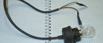
Monitoring the network and searching for the fault location is carried out using an indicator screwdriver and a tester. A screwdriver allows you to distinguish a phase wire from a wire with zero potential and check the presence of line voltage on the phase wire. When the tip touches a working phase wire, provided that one of the fingers lies on the contact of the handle, the orange neon light lights up, Figure 4. To control the voltage, the touch is made at any convenient point, for example, on the contacts of a switch.
Rice. 4. Checking the phase with an indicator screwdriver
The tester allows you to determine the actual value of the mains voltage. To measure, probes simultaneously touch the bare parts of the phase and neutral wires. Indications when measuring phase voltages should be 220 V or differ from it by no more than 5 - 10 V.
Techniques for finding a break point
Restoring the normal functioning of electrical wiring begins with localizing the location of the fault and identifying its cause. For three-phase and single-phase networks, the procedures are the same. They are carried out by eliminating known good parts by checking the presence of a phase. Then the potentially faulty area of the network is divided into smaller parts, each of which is checked separately.
Great help at the first stage of the search is provided by the fact that the so-called upper (for chandeliers and other ceiling lighting devices) and lower (sockets) apartment wiring inputs are made from different phases. Therefore, a non-working upper light while the TV is functioning immediately indicates that the phase for organizing the lower input is working.
When checking, use an indicator screwdriver and a tester. When monitoring the overhead light, to access the contacts, you should unscrew the bulb and exercise some caution. In this case, there is a high risk of short circuiting the cartridge contacts with the tip of a screwdriver or the tips of the tester wires.
Localization of the fault location
The main means of localizing the location of a circuit break is sequential monitoring of its components. It is taken into account that the electric current flow circuit always contains 2 wires.
With a daisy chain connection, checks begin from the furthest one and are carried out towards the junction box. For cases of direct connection of the consumer to the wiring without a loop, you can immediately proceed to monitoring the junction box with checking the phase and neutral conductors.
When checking phase wires, visual inspection of individual circuit components is widely used. The malfunction often manifests itself in the form of soot and traces of melting of the plastic housing or polymer insulation, Figure 5.
Rice. 5. Internal breaker damage
To detect the loss of zero, for example, in a socket, if the phase is working, it is enough to connect a light bulb that will not light.
Kinds
Two-key switches are available in several versions:
- with backlit keys;
- combined with a socket;
- designed as a pass-through switch.
By design, switches are available for outdoor or indoor installation. Connecting a two-button light switch depends on the specific situation. It is necessary to decide where the switch for two chandeliers will be used and decide which option is needed.
There are options for two-gang switches that have four contacts instead of the standard three. They are two isolated single-key switches combined in one housing. They are called modular.
For indoor installation
This device is the most common. It is used in office and residential buildings. Installed in a mounting box, which is mounted in a plasterboard or concrete/brick wall. Due to the fact that the switch is hidden in the wall, it is also called “recessed”. The wires are supplied to it in special grooves called grooves. If the switch is fixed in a framed plasterboard wall, then the cable to the switch is laid in a corrugated pipe.
For outdoor installation
When installing open-type wiring, outdoor switches are used. They are mounted on a non-flammable base, and the wires are connected to them in cable ducts, metal hoses, corrugated plastic pipes or on top of the wall on porcelain insulators. Most often, the connection diagram for a two-button switch for two open-type light bulbs is used in wooden houses of gardening partnerships. Outdoor installation is also used in sheds, garages, basements and other utility rooms.
Connecting a stranded wire
If you have multi-core wires, then there is no way to do this without first forming a ring and soldering it. Otherwise, 100% reliability and durability cannot be achieved from such a connection. The contact will simply be crushed by the screw head.
In this case, the veins are first divided in half and twisted.
After which a free ring is formed around the bolt.
It then needs to be soldered and then connected.
The extra tails after the ring are bitten off.
Before all these procedures, do not forget to first place the “butt” from the cartridge on the cable itself.
Otherwise, you won’t be able to assemble it after this and will have to twist the cartridge a second time.
The second disadvantage of carbolite products is connection time.
The entire process of disassembling and reassembling, unscrewing and tightening screws, takes from 5 to 10 minutes. Therefore, the procedure for “loading” a carbolite cartridge cannot be called quick.
What to do if the type of switch or chandelier does not match the required
It may happen that the old chandelier had several groups of lamps and was turned on from a two-key switch, and after the repair it was decided to install a regular single-arm switch. Or vice versa, instead of a simple chandelier, a multi-arm chandelier was installed. How to properly connect the lamp?
There are more keys than conductors in the chandelier
If more wires come out from the double switch (and from the ceiling, respectively, to the chandelier) than are necessary to connect the chandelier (most often - four, one of which is grounding), then the most radical way is to replace the switch and leave some of the wires free.
Or you can connect a simple chandelier to a double switch. You can combine the wires coming from different switch keys. The connection can be made on the ceiling in front of the chandelier connection block or in the switch itself (in this case, the second wire to the chandelier must be left free). Then the chandelier will be turned on by any key, and to turn it off you need all the keys to be in the off position.
How to connect a chandelier to a two-key switch
The number of keys is less than the number of conductors in the chandelier
If you do not repair the wiring, then connecting a chandelier with two arms or more to two wires is possible in only one way - by combining all separate groups of lamps into one.
As a last resort, if the wiring allows, you can use two switches.
The situation is completely different when connecting a modern chandelier with a remote control. Regardless of the number of groups of light bulbs, the connection of the chandelier to the switch is carried out by wiring with two wires, and the switching of different groups of lamps is carried out by a control unit located in the luminaire.
What opens the light switch - neutral or phase?
Its connection diagram is the simplest, however, there are nuances that must be observed. It must be remembered that when carrying out any repair work with electrical wiring, it is necessary to turn off everything, usually turn off the input circuit breaker in the electrical panel and take measures to ensure that no one accidentally turns it on, especially if the panel is located on the street or stairwell of a multi-story building. Power is supplied to the branch box from the electrical panel via a three-wire cable. Also, two more cables come into the branch box: a two-wire one from the switch and a three-wire one from the lamp.
As we see in the diagram, the phase marked with the Latin letter L and zero, but if you open and connect zero, then the load on the switch and.
How to connect a switch to a chandelier.
In order to correctly connect a two-key switch to a chandelier, you must first understand the ceiling wiring. According to Euro standards, there are strict rules for the color of each wiring, which must correspond to phase, neutral and ground. But domestic electrical installers (especially for old apartments) use the cable that is at hand. Therefore, you always need to clarify the function of each wire.
In order not to make a mistake and correctly identify the phase wire on the ceiling (or from the wall), you must:
- separate the wires to the sides (so that when voltage is applied there is no short circuit);
- apply voltage by pressing the switch keys;
- Check with a voltage indicator or multimeter which wires are receiving voltage.
So, you have decided which phase wires “ L”
", and which zero "
N
". Next, you need to correctly connect the double switch to the chandelier at the installation site:
- The neutral working wire “ N
” can be connected into one and connected to two lamps in one connection. - Each phase wire “ L
” must be connected to a separate connection for each lamp.
The correct diagram for connecting a switch with one key to a chandelier is shown in Figure No. 3.
Fig. 3 - diagram of connecting the switch to the chandelier.
Take up a phase - don’t say you’re not an electrician
What's next? It would be useful to recall some of the tragic circumstances of this incident.
- one wall - like after a machine gun fire
- on the other side of this wall, the wallpaper was cut and the power box to which the corridor outlet was connected was opened. By the way, the twists there were burnt, I tightened them up
- In the bathroom (and not only there) expensive renovations have been made, the wire for the lamp comes out of the expensive tiles above the door
- the owner of the apartment is the deputy head of the city's Ministry of Emergency Situations
- It's the owner's birthday in a few days
- it is unknown who will now pay for the repairs (there were hints that I broke it in vain)
- it is known that not a single electrician will now undertake to continue (and most importantly, complete) my research
Conclusion - we need to finish what we started. See the titles of this article and this subtitle.
Source
Errors when connecting a two-key switch
The first mistake that an illiterate specialist can make is to connect not a phase to the switch, but a zero.
Remember: the switch must always break the phase conductor, and in no case the zero conductor.
In the opposite situation, the phase will constantly be on duty on the base of the chandelier. And simply replacing a light bulb can end very tragically.
By the way, there is another nuance due to which even experienced electricians can break their heads. For example, you wanted to check directly at the contacts of a chandelier whether the phase arrives there through a switch or zero. You turn off the two-key switch, touch the contact on the chandelier with a Chinese sensitive indicator - and it lights up! Although you assembled the circuit correctly.
What can be wrong? And the reason lies in the backlight, which is increasingly included with switches.
A small current, even when turned off, still flows through the LED, applying potential to the lamp contacts.
By the way, this is one of the reasons why LED lamps blink when turned off. How to deal with this can be found in the article “6 ways to solve the problem of flashing LED lamps.” To avoid such a mistake, you need to use not a Chinese indicator, but a multimeter in voltage measurement mode.
The second error is when the phase supply conductor is connected not to the common contact of the switch, but to one of the outgoing ones. In this case, the circuit will not work as expected. All lights will light only if you press two keys at the same time. But if you press only the key to which the phase does not come initially, the chandelier will not light up at all.
If you moved into a new apartment, where you were not the one who connected the chandelier, and it behaves in such a strange way, that is, it does not react as expected to the two-key switches, then the problem is most likely due to such an erroneous installation of the supply wires. Feel free to disassemble the switch and check the common contact.
If you have an illuminated switch, an indirect sign of such an incorrect connection may be the neon bulb not working properly. Why indirect? Since here everything depends on which key you start the phase on.
The third common mistake is connecting the neutral wire on the chandelier not to the common zero in the junction box, but to one of the phase wires. To avoid this, use and follow the color coding of the wires, and even better, if you don’t trust the colors, check the voltage supply using a high-quality indicator or multimeter before turning on the lamp.
What happens if the switch is connected incorrectly?
Whether the network is three-phase or single-phase, the zero (neutral) conductor must be grounded, so in principle it is much safer than the phase conductor. In fact, generators and transformers from which the electrical network receives energy are grounded. If the neutral conductor is not grounded, then there has been an accident in the network, a break in the neutral conductor.
Usually in everyday life we use single-pole switches, that is, those that open or close only one wire when you press a button. Let's say there is a chandelier hanging on the ceiling, receiving power from a single-phase household network of 220 volts. There are two wires going to the chandelier, one of them is phase, the second is zero. The switch is installed in the gap of one of these two wires.
Let the switch be on the phase conductor, and it has been switched to the “off” state. Then both conductors through which electricity is supplied to the chandelier will be de-energized, their potentials will be equal to zero, because the neutral conductor, which was not interrupted by the switch, by definition has zero potential, and the phase conductor is interrupted by the switch, that is, there is no phase conductor on it voltage.
Both conductors are safe, you can change a light bulb, repair a ceiling, remove a chandelier, etc., without fear of being exposed to phase voltage and receiving an electric shock. Although it is better in this case to be safe, turn off the machine in the electrical panel.
How not to do it
But what if the switch is mistakenly installed in the gap of the neutral rather than the phase conductor? In this case, even if the switch is in the “off” position, one phase conductor still approaches the chandelier. The second conductor is not connected to anything.
If in such a situation you start changing a light bulb, repairing a chandelier, or working on the ceiling, you may inadvertently touch a phase wire and get an electric shock, especially if you are standing on a conductive stepladder that accidentally comes into contact with something grounded or even stands on the ground.
Replacing a light bulb can result in tragedy and loss of life. It’s okay if you stand on a wooden stool, in rubber boots, and work in protective gloves. Everything can end well here. But under unfavorable circumstances, a switch on the neutral conductor can turn into a mortal danger.
The principle of operation of a standard, familiar light switch is quite simple; when you press a key, it physically breaks (or connects) the electrical circuit laid to the chandelier, sconce or any other lamp.
And since the lamp requires phase and neutral conductors to operate, you can, in fact, install a switch in the gap of any of them, and the system will work, at first glance, equally correctly.
Perhaps this is why the question quite often arises, what according to the rules should the switch open phase or neutral and why?
The first part of this question, namely, what the switch should break phase or zero, has an answer in the PUE , the rules for electrical installations, the main document that regulates the rules and regulations of electrical installations.
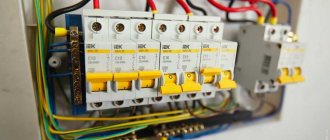
In the latest, currently relevant, 7th edition of the PUE, in paragraph 6.6.28 , the following is stated:
In three- or two-wire single-phase lines of networks with a grounded neutral, single-pole switches can be used, which must be installed in the phase wire circuit , or two-pole ones, and the possibility of disconnecting one neutral working conductor without disconnecting the phase conductor must be excluded.
Installation of connections for a two-gang switch in a distribution box
The following cables can enter the junction or distribution box:
- power cable from the machine in the panel
- cable going down to the switch
- one (if you have a chandelier with two lighting circuits) or two cables (if the light points are in different places) to the outgoing lamps
To avoid confusion, follow the following order:
First of all, connect all neutral conductors. They are usually blue. Zero does not pass through the two-key switch and goes directly from the panel to the lamp, through the connections in the distribution box.
All stripped wires can be connected using Wago quick-release terminals. Although everyone has a different attitude towards them, they are an ideal option for lighting circuits with minimal loads.
Next in order is protective grounding. This is a yellow-green wire. If you do not have a grounding conductor in your apartment or the lamp body is insulated and the cable is two-core, then this connection will not be in the junction box.
It remains to connect the phase conductors. Here you need to be extremely careful. First, clamp the phase that comes from the power supply into the Vago terminal block. Then insert a wire into the same terminal that comes from the common phase contact of the two-key switch.
You should have 4 free, unconnected wires left. Two of them are the wiring that goes to the chandelier or sconce, and the other two wires are phases connected to the lower outgoing contacts of the two-key switch. Take two more clamps and SEPARATELY connect these conductors through them. Thus, you will connect two lighting circuits to the lamps independently of each other.
What colors should the wires have in the electrical wiring of an apartment?
Any conductor purchased for electrical wiring must contain a core with a blue (blue) braid. It is this that is recommended to be used in the network as a neutral wire. If the apartment has a third wire - direct grounding, it is recommended to run a yellow-green wire on it. All other wires (it can be white, brown, black, etc.) are used as phase-carrying wires. So to the question whether the switch breaks phase or zero, the answer will be unequivocal - phase, and this core will not be blue or green.
If the wires in your apartment are mixed up, it means that the installation of electrical wiring in it was not carried out by professionals and, most likely, it has already undergone repairs.
How to change a switch if you are not an electrician? - Home owner
To change a switch in an apartment or office, you don’t have to understand the electrical wiring at all, where the phase or neutral is located. With the switch everything is very simple, if you first turn off the voltage in the panel and know how to handle a screwdriver. We'll assume you can do it. So, how to change the switch yourself?
Where to start?
Put aside your fear of electricity (if you have one, of course) and boldly get down to business. In this case, you will receive three pluses. Firstly, save your time waiting for the master.
Secondly, save your money. And thirdly, you will gain experience working with electricity.
If it seems to you that this is not entirely easy, you can use our instructions and you will succeed, and making such a replacement is no more difficult than changing an outlet.
Important! Before you begin any action, you must be sure that the power to the outlet is turned off!
Tools and materials for work:
- Switch to replace the old one:
- Phillips or flathead screwdriver;
- Small pliers;
- Indicator screwdriver.
- For electrical safety purposes, we turn off the circuit breaker that supplies voltage to the switch, and after turning off we check that the switch has stopped turning on the light. This means that it is de-energized and you can start replacing it.
- Unscrew the screw that secures the decorative trim and remove it. Now we loosen the screws that hold the spacer tabs on the sides of the switch mechanism and remove the mechanism from the wall. Using a screwdriver, disconnect the electrical wires from the switch terminals, remembering their connection to the contacts.
- If the switch is a single-key switch, then two wires fit to it and they can be connected in any order, but it is better to determine where the phase wire is located. To do this, you need to separate the wires so that they do not touch each other and turn on the machine in the switchboard. Using an indicator screwdriver, we determine the phase. The indicator on this wire will light up. Turn off the machine. We connect the phase wire to terminal L on the mechanism, the remaining wire to the second terminal. We install the mechanism into the socket and secure it with spacer pads.
- If the switch is a two-key switch, first we find the phase wire with an indicator screwdriver, we also connect it to terminal L, and the remaining two to terminals 2 and 3 on the mechanism.
- We put on the decorative cover, secure it with a screw, turn on the machine and check the operation of the switch.
In addition, watch a short video about replacing a switch with your own hands without calling an electrician and remember, if the wiring is not completely old, then doing such work will not be difficult for you.
Main causes of the problem
As you already understood, the reason for the appearance of two phases on an outlet is most often. Loss of contact can occur on the floor panel, at the entrance to the apartment, in one of the distribution boxes, and even just in the wall.
If the wire burns out in the electrical panel, the lights in the apartment will go out, but the sockets will still work, but only when you turn on an electrical appliance or lighting in the room. If you turn everything off and check the voltage in the outlet, you will see that there will be only one phase.
Another case is when a zero break occurs in the distribution box of one of the rooms. In this case, the light will stop turning on only in this room, in the rest everything will work as before. To solve the problem, you will need to open the junction box and restore it.
Another common reason why there are two phases in the socket is old wiring in which plugs are screwed into the input instead of automatic switches. If only one plug, zero, is knocked out, voltage will appear in two sockets. To prevent this from happening, we recommend replacing the electrical wiring in the apartment with a modern one - with.
There is also a common situation when a break occurs directly in the wall due to your unprofessionalism. Before hanging a picture, be sure to find the electrical wiring in the wall so as not to damage it with a nail (including yourself). If you interrupt only the neutral conductor, two phases will appear in the sockets. This also includes damage to the wire by rodents, which can exist in the voids of the panels of apartment buildings. We talked about this in the corresponding article.
So, we told you why voltage may appear in two sockets of an outlet, how this happens and what to do to solve the problem. Now I would like to explain how to immediately understand that wire N has been damaged and it is not both phases, but one that has flowed through the second power line.
The situation is clear - the light went out in the apartment and you immediately decided to use a sampler. Having noticed that the indicator shows the phase on two wires, you thought that these were two phase conductors in your electrical wiring. As we have already said, everything is far from the case and you can verify this as follows:
Using a multimeter, check the voltage in the socket; if it shows 0, then you have only one phase, flowing to the neutral conductor.
This is the surest way to determine a malfunction, because an indicator screwdriver is an extremely inaccurate testing method. The indicator may be triggered and show a second phase, although in reality there will be only one.
During normal operation of the outlet, checking the presence of voltage, the picture should look like this. When you touch a phase wire, a light warning should appear, and when you touch a neutral wire, the indicator light should not light up.
But if the socket does not work, and the indicator shows two phases on the wires in the socket,
what to do and how can this happen?
This phenomenon occurs quite often, usually in houses with old or poorly executed electrical wiring. two phases in the socket come from?
, let's look at the possible reasons for their appearance:
Connection diagrams for a two-key switch
When connecting the switch, remember that the phase that comes from the panel is supplied to its input. This is the basic rule. This is the only way the connection will be correct. The phase is taken in the distribution box, which is usually located above the switch (sometimes, with lower wiring, below it) in the distribution box.
Please note that work is carried out with the voltage turned off. If there is a circuit breaker through which the lighting is powered, turn it off
If the wiring is old, unscrew the plugs. Before work, make sure that there is no voltage on the wires (touch all with an indicator screwdriver).
How lighting works in bathrooms
This apartment has aluminum wiring, which is a big minus. When opening the bathroom switch, it turned out that it was working properly and that the apartment was one of those cases where it was not done entirely correctly - the switch opens zero, not phase.
Why is this done? I have asked myself this question more than once. In my apartment, the switch also opens zero.
For safety reasons, it has always been a rule that the light switch must open a phase. This is done so that when replacing a light bulb or wiping a chandelier, the likelihood of electric shock is minimal. It is enough to turn off the switch - and you can safely change the lamp with your bare hands or even dig into the socket. Naturally, first check the absence of a phase with an indicator screwdriver.
So why didn't electricians in older houses (more precisely, in houses where aluminum wiring is used) adhere to this important and simple rule? It turns out that the wire was simply with colorless (more precisely, white) insulation, and no one bothered to distinguish phase from zero. Are the sockets working? Are the lights on? What else does? The phase was observed only in the panel on the site, when connecting the meter and circuit breakers. And then, not always.
If done according to the rules, the lighting must go through a separate power line, through a separate circuit breaker with a current of no more than 10A, and all connections must be made in the distribution box above the switch. The phase opening has already been discussed above.
But these are the rules, but what really happens?
A brief excursion into theory
Today we will not delve too deeply into the theoretical foundations of electrical engineering, but will try to briefly explain the essence of the problem. For those who wish to become more familiar with this issue, we recommend reading a series of articles on the physics of alternating electric current on our website.
Standard switch installation.
Let us take as an example a fragment of a household electrical network, where the connection of an electric lamp and a plug connector (socket) is organized.
Fragment of a household network with connection of a lamp and socket
Designations:
- L – phase.
- N – zero.
- Ps – socket.
- Sw – light switch.
- Lm – lamp.
As is known, in single-phase circuits the electric current (Ì) flows from phase to zero. In the above figure, the switch SW is in the open position, therefore the lamp will be de-energized, which can be verified by measuring the voltage U2. In this case, the operating potential U1 corresponding to the phase voltage will remain on the plug connector and the part of the network up to the switch (marked in red). This is the normal operating mode for this circuit, where the switch opens the phase wire.
Please note that if you take measurements with a voltage indicator, it will show the presence of a phase on one of the contacts of the plug connector and its absence on both contacts of the lamp socket.
Setting the switch to zero
Now let's see what happens if you swap the phase and zero, or, what is more common in practice, set the switch to zero, and not the phase wire.
Switch installed incorrectly
Outwardly, such a change will not manifest itself in any way. The lamp will turn on and off in the same way as in the previous example, and a potential difference will be present at the contacts of the socket. But, certain nuances arise, which manifest themselves in the presence of voltage at the contacts of the socket and part of the zero line between the lamp and the switch. This is easy to verify using an electrical probe.
This connection option carries a potential risk of electric shock when attempting to replace or repair the lamp.
It is typical that measuring the presence of voltage between the contacts of a lighting fixture socket with a voltmeter will not bring results. The device will show “0”, since the contacts will have the same phase potential level.
Summarizing the results of the chapter, we can state that incorrect connection of switch contacts in the distribution box does not have a significant effect on the operation of electrical appliances connected to the outlet. In addition, we found out about the need for the combined use of measuring instruments (voltmeter and probe).
Problems with zero loss
The rupture disrupts the balance in the system, the flow of different-phase currents stops, and the voltage in the system changes.
As an example of how two phases can occur in an outlet, consider circuit AB. Line voltage is supplied to rooms A and B. The resistor is connected in series and includes two components. Due to the total resistance (Ra + Rb), a current (Lab) passes through the circuit, which is calculated according to Ohm's law. This indicator is common for both rooms.
The voltage reduction in the premises becomes unequal - it depends on the level of resistance inherent in operating electrical appliances. If in one of the apartments all household appliances are turned on, and in the other the consumption indicator is lower, all 380 V will end up in the apartment with a higher current, which will lead to failure of the equipment, therefore 2 phases are not allowed in the outlet.
You can reduce the risk of damage to electrical equipment by using a voltage monitoring relay. Such a relay is installed in the apartment electrical panel. The relay operates in automatic mode. Its task is to turn off the electricity supply in a timely manner in the event of an emergency.
Connecting wires in a ceramic socket
The ceramic device is not a dismountable product, just like its contacts. This is where the main disadvantages arise.
These contacts are rolled and eventually weaken over time. As a result, heating occurs, followed by burnout or too frequent failure of the light bulbs themselves.
Such cartridges also have the sin of twisting the skirt itself along with the light bulb. After such a defect, it is better to replace it entirely.
Of course, you can initially solder the contacts in the folding areas or crimp the unscrewed skirt again, but the vast majority do not bother with this and simply buy a new one.
The main advantage of the ceramic cartridge is its simplified connection system. Everything happens much faster here.
Firstly, there is no need to disassemble the device itself into three parts. Secondly, completely unscrew the screws.
It is enough to loosen them slightly and insert the stripped wire core into the contact space.
Then tighten the screw with maximum force.