Which side should the phase in the socket be on?
Which side should the phase in the socket be on?
Replacing electrical wiring requires connecting conductive elements (wires and cables) to all sockets and switches in the house. Single-phase sockets require a minimum of two current-carrying wires. If there is grounding, the number of conductors increases to three.
In this case, an important component is the correct location of the phase and zero in the socket. What is it for? For example, some electrical appliances refuse to work due to the fact that the phase is supplied to the wrong contact.
Home electrical wiring: finding zero and phase
You can determine at home where which wire is located in different ways. We will analyze only the most common ones that are accessible to almost anyone: using an ordinary light bulb, an indicator screwdriver and a tester (multimeter).
About the color marking of phase, neutral and ground wires in the video:
Checking with an electric lamp
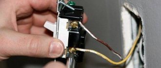
Before you begin such a test, you need to assemble a testing device using a light bulb. To do this, it should be screwed into a cartridge of suitable diameter, and then secured to the wire terminal, removing the insulation from their ends with a stripper or an ordinary knife. Then the lamp conductors must be applied one at a time to the cores being tested. When the lamp lights up, it will mean that you have found a phase wire. If you check a cable with two cores, it is already clear that the second one will be zero.
Checking with an indicator screwdriver
A good assistant in work related to electrical installation is an indicator screwdriver. The operation of this inexpensive instrument is based on the principle of capacitive current flowing through the indicator body. It consists of the following main elements:
- A metal tip shaped like a flathead screwdriver that is applied to wires for testing.
- A neon light bulb that lights up when current passes through it, thus signaling phase potential.
- A resistor to limit the amount of electrical current that protects the device from combustion under the influence of a powerful flow of electrons.
- A contact pad that allows you to create a circuit when you touch it.
Professional electricians use more expensive LED indicators with two built-in batteries in their work, but a simple device made in China is quite accessible to anyone and should be available to every home owner.
If you check the presence of voltage on the wire using this device in daylight, you will have to look more closely during the work, since the glow of the signal lamp will be difficult to see.
When the screwdriver tip touches the phase contact, the indicator lights up. In this case, it should not light up either at the protective zero or at the grounding, otherwise we can conclude that there are problems in the connection diagram.
When using this indicator, be careful not to accidentally touch a live wire with your hand.
About determining the phase clearly in the video:
Checking with a multimeter
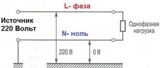
To determine the phase using a home tester, you need to put the device in voltmeter mode and measure the voltage between the contacts in pairs. Between the phase and any other wire, this indicator should be 220 V, and applying probes to the ground and protective zero should show the absence of voltage.
Which side should the phase in the socket be on?
Here everything largely depends on what power source is connected to the outlet. There is such a thing as a polarized and non-polarized plug.
In the first case, when a polarized plug is connected to a socket, it is very important that a phase goes to one specific wire, and a working zero to the other. If this is not taken into account when connecting some electrical appliances, problems may arise in their operation.
For example, some heating boilers require connection via a polarized plug. That is, for their operation it is very important that the phase is supplied to a specific wire.
When connecting non-polarized plugs, which are mainly used to connect most electrical appliances in the house, it makes no difference which side the phase in the outlet will be on. In simple words, alternating voltage for their operation precisely implies the absence of pluses and minuses.
Electrical appliances for which it is important where the phase will be
First of all, these are some models of gas boilers. For them, it is very important to connect a phase to a specific core of the network cable.
These are so-called “phase-dependent” boilers with an electric flame controller. If you connect a phase-dependent boiler incorrectly, this can lead to serious operational problems, even an explosion due to a gas leak.
Important note! To make it easier to find the phase, most electricians still prefer this rule, when the phase in the socket is connected on the right side, and the working zero on the left. This rule facilitates the process of further electrical repair work.
However, it is important to understand that this is not dictated by the PUE. Therefore, before you climb into the socket, you definitely need to check with an indicator screwdriver which side the phase is located on and which side the zero is located on.
The concept of polarized and non-polarized plug
There are two types of single-phase sockets used in everyday life.
Non-polarized plugs and sockets with and without grounding are used in most European countries, in the former USSR and in some other countries.
Polarized plugs and sockets
These devices can be turned on only in one position and supply “zero” and “phase” to the electrical device through certain wires. In devices connected using such plugs, protective switches are installed only on the phase wire.
There are different types of polarized sockets that are used in different countries:
In addition to those listed above, there are other, less common types of polarized plugs and sockets.
Is zero on the right or left in old sockets?
To connect an old-style socket, only two wires are used - one phase, the other neutral. The phase can be connected to the right or left.
Some modern electrical appliances are connected strictly according to the instructions, and therefore the location of the phase wire plays an important role. Installation is carried out only by professionals. For example, a gas boiler that has a built-in electrical controller that does not have a plug and is therefore permanently connected.
The location of the phase is not indicated in the rules for installing electrical appliances. Electricians adhere to a certain standard: phase on the right side, zero on the left.
Does the location of the phase and zero in the socket matter?
Sockets used in the CIS countries allow plugs to be turned on in two ways, and the plugs themselves are arranged symmetrically, so when turned on, the phase in the socket can be connected to any of the pins of the plug.
For the operation of most electrical appliances, the polarity of the plug in the outlet does not matter. In turn, when turning on the plug, ordinary consumers do not pay attention to its position. The exception is plugs, in which the cable is located at an angle of 90° to the pins. These devices are turned on in a way that is more convenient for them to use.
There is an opinion that, according to the PUE and other regulatory documents, the phase should be connected to the right terminal of the socket, but this is not so. Not a single document or instruction indicates the correct position of the phase in the socket and where to connect it is determined by the installer during installation.
Given the possibility of turning on the device in any way, circuit breakers in electrical appliances disconnect both supply wires.
Does pin placement matter?
The current in our power supply networks is, of course, variable. There are no “pros” and “cons” like batteries/accumulators here. There are also no markings on the sockets themselves: they are non-polarized. That is, for these sockets the polarity of connecting a household device is not important, so the plug can be plugged in without regard to the orientation. And it’s hard to imagine that the housewife, before turning on the iron, would stand and think about where the phase is in the socket and how to insert the plug correctly. Therefore, given that we use non-polarized sockets, formally there is absolutely no difference on which side the phase will be located.
The location of the contacts is important only for a narrow range of equipment, for example, for phase-dependent boilers. In such boilers, flame control is carried out electrically. That is, a phase is supplied to the flame control electrode to measure the leakage current to ground. Therefore, in this case, as the manufacturer notes, it is fundamentally important which side the phase comes from. But the manufacturer himself recommends connecting the boiler not to an outlet, but to a separate machine, so in principle there will be no problems with the orientation of the plug.
For which devices is it IMPORTANT where the phase is located in the socket?
Which side of the phase in the socket is important only for some electrical appliances, which will not work if switched on incorrectly. This feature is inherent in the design of the devices and is indicated in the operating instructions. As a rule, “specially trained people” are involved in connecting these devices.
These are gas boilers and water heaters with an electric flame presence controller.
Answer from one of the boiler manufacturers
If the gas burner flame goes out while the valve is open, it will lead to gas leakage and explosion. In the design of gas heating boilers and some types of other gas installations, electrical flame control is used.
The fire conducts electric current, so a refractory electrode is placed in it, a voltage is applied to it, and the leakage current is measured. Its presence indicates the presence of a flame in the burner.
"Phase" on the left, "phase" on the right. How to do it right
Many people ask the question of how to correctly connect phase conductors to household sockets: on the left or on the right. Having entered such a question into a search engine, you are doomed to entertaining reading until the morning. The answer options that the Internet is replete with are either directly opposite or not relevant to the essence of the question. Many resources have similar topics, but the format of most of them, where the subjective opinion of individual participants overshadows all reasonable arguments of others, does not allow an unprepared user to receive an unambiguous answer in a reasonable time.
Some believe that they are on the left, because “we have always done it this way.” The latter are looking for an answer by ringing plugs, power cords and switches built into devices, thus trying to determine (from the terminal block, for example, a washing machine) where the phase in the socket should be, on the left or on the right.
A separate argument found on the Internet is the alleged requirement of some manufacturers, for example gas domestic boilers, to connect equipment (already with a flexible cable with a plug supplied by the manufacturer) in a phased manner, i.e. plug phase to socket phase. The term “phase-dependent boiler,” in my opinion, is simply inappropriate when the boiler manufacturer equips it with a standard non-phasing plug. Well, what does “dependent” mean if the plug supplied by the manufacturer can be plugged into the outlet either way?
Answer from one of the boiler manufacturers: Gas boilers and burners use the principle of monitoring the presence of a flame using an ionization probe. The burning gas is electrically conductive, so an electrode is placed in the flame, a phase is applied to it and the leakage current to ground is measured. Therefore, it is fundamentally important which wire to apply the phase to. In common parlance, such boilers are called phase-dependent. The boilers are not supplied with any plugs; it is considered correct to connect the power supply to the boiler permanently (not through an outlet) through a separate circuit breaker. In this case, no problems with “fork flipping” occur.
Fork options https://ru.wikipedia.org/wiki/Schuko. The plugs and sockets used in the Russian Federation are non-polarized, the phase and zero connections are not controlled, unlike the plugs and sockets of the so-called French standard CEE 7/5 https://ru.wikipedia.org/wiki/CEE_7/5
The majority is inclined to believe that the “phase” in the socket should still be on the right, citing as arguments certain GOSTs and other rules, their own arguments, etc. Unfortunately, subjective reading and interpretation of regulatory documents further confuses the user. One of the forums even provides “proof” that the “phase on the right” reduces the level of electromagnetic radiation from computer system units. The only confusing thing is that the format of that article partially contains elements that were ordered and sold on websites, and the article itself is completely illiterate and full of contradictions. For those who are interested, here: https://www.forumhouse.ru/threads/259518/ this “material” was broken down into pieces, so much so that the administration of the resource was forced to delete it.
An alternative opinion on where the phase in the socket should be, on the right or on the left
There is an opinion among some audiophiles that supposedly an inverted plug from radio equipment changes the sound quality. It’s hardly worth talking about this seriously if the manufacturer has equipped the equipment with a standard plug that can be plugged in either way. In fact, since our sockets are non-polarized, i.e. We can plug the plug in either direction, and the connection of the phase conductor in the socket is not yet regulated in any way, so it does not really matter where the phase will be in the socket, on the left or on the right. But have you ever seen a housewife check where the phase is in the plug before turning on the iron? So I don’t! The main thing is that there is good electrical wiring, a correctly selected protective device and reliable grounding.
Correct phase position in the socket
To sum up, where should the phase be, left and right, we answer.
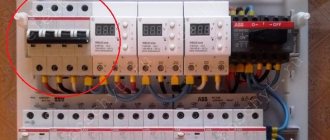
Household sockets in the Russian Federation do not imply “polarity” of connection, i.e. where the phase and where the neutral are are not regulated for them. Thus, it will be correct to do both. For professional electricians, we still recommend using some uniformity in their work: the phase in the socket is on the right and here's why. During installation and subsequent testing of sockets, we use such a device to check the correct connection of the phase, neutral and ground conductors.
This device allows you to instantly determine the correct connection of all conductors in the socket, the presence of voltage, a grounding test and the functionality of the RCD (30 mA circuit breaker test, 120 ms ± 40 ms). As you can see in the figure, the “phase” in the socket for testing should be on the RIGHT. Therefore, for the convenience of testing and uniformity of the installation, we recommend connecting the “phase” in the socket on the right. We hope that this rule will appear in the norms at least as a recommendation.
What the regulations say
One of the primary sources of rules for any electrician is the PUE, and frankly speaking, dear readers of the “Electrician in the House” website, in this book I did not find any requirements regarding which side to connect the phase in the outlet. Not because I didn’t search well, but because there are no such requirements in the Electrical Installation Rules (PUE). If anyone thinks differently, please link to the item in the comments.
But there is one BUT here. This standard is approved by the British Institute and adopted for countries such as Great Britain, Pakistan, India, South Africa, etc.
Another document that mentions the connection of phase and neutral in the socket GOST 30851.1-2002 clause 8.6. True, here there is only a description of which side to make the connection, it just says that the phase is connected on the right, zero on the left, and grounding at the top in the middle. I am attaching a screenshot from this document.
How to determine phase and neutral in a socket?
To understand what phase and zero are in a socket, an ordinary person (not a specialist) does not need to delve into the electrical jungle. As an example, let's take a regular plug socket that receives alternating current.
There are two electrical wires going to the outlet - neutral and phase. Current flows through only one of them - the phase phase (also called the working phase). The second wire is neutral (or zero phase).
Zero and phase in old sockets
To connect the old outlet, use two conductors. Some of them are blue (working neutral conductor). This wire carries current from the source of electricity to the household appliance. If you grasp the live wire but do not touch the other wire, you will not receive an electric shock.
The second wire in the socket is a phase wire. It comes in a variety of colors, including blue, green-yellow or light blue.
Note! Any voltage exceeding 50 volts is life-threatening.
Phase and neutral in a modern socket
Modern devices have three wires. The phase comes in any color. In addition to phase and neutral, there is one more wire (protective neutral). The color of this conductor is green or yellow.
Voltage is supplied through the phase. Zero is used for protective zeroing. The third wire is needed as additional protection - to draw in excess current during a short circuit. The current is redirected to the ground or in the opposite direction - to the source of electricity.
Note! It makes no practical difference whether phase and zero are located on the right or left. However, most often the phase is located on the left and the zero is on the right.
Determination of phase and zero with a two-pole voltage indicator
A two-pole voltage indicator consists of two working parts connected to each other by a soft wire. This kind of tool belongs to the professional category. Often on one of the working parts there is a scale in the form of indicator lights indicating the presence of the corresponding voltage 24 V, 48 V, 110 V, 220 V, 380 V (values may vary depending on the brand).
Friends, I should note the fact that not every bipolar voltage indicator can determine where the phase is and where the zero is.
As an example, the photo shows the PSZ-3 indicator, which is designed for an operating voltage of up to 500 V. If there is voltage, the PSZ-3 indicator emits an intermittent sound signal (begins to beep) and the indicator light lights up.
If you touch one working part of the phase conductor, the indicator light will start to light, and the buzzer will emit a continuous beep.
In this simple way, you can determine where the phase is and where the zero is with a two-pole indicator.
What methods are prohibited for verification?
You can often find a forbidden method used by electricians to find phase and zero. This method involves the use of "pilot lamps". That is, you take an ordinary light bulb and screw it into a socket to which the wires are connected. The wires are connected between phase and zero - if everything is normal the light bulb lights up, if it doesn’t light up... it means it doesn’t light up...
Firstly, this method is ambiguous, it does not allow you to say with complete confidence whether there is a phase or not (besides, if the zero is broken, a person may think that there is no phase and reach into the box with his hands...). Secondly, checking the absence of voltage with test lamps is prohibited by the “Rules for the Safe Operation of Electrical Installations”.
The prohibition in using “control lamps” is that when checking the voltage in a three-phase network between “phase” and “phase,” the lamp is connected to a voltage of not 220 Volts, but 380 Volts, as a result of which the glass bulb of the light bulb (which is designed for 220 V ) may not survive and explode, thereby injuring a person with fragments.
Also, do not use running water or radiators - this is dangerous not only for yourself, but also for others.
Also, do not rely on the color coding of the wires. These are just additional methods of orientation and determination. Although the markings must be observed, the installation is not always carried out by competent electricians. Often a phase is connected to the ground wire.
Friends, do not believe those people who say that they will teach you how to determine phase and zero without instruments - this is a myth. It is impossible to perform this action using a potato, a glass of water or a plastic bottle. In these ways you put yourself in danger - you can pay for it with your life. In any case, you need equipment, even the simplest ones. Don’t be too lazy to go to the store and buy a regular voltage indicator - it costs a penny.
Similar materials on the site:
- Attaching the cable to a concrete wall
- Find out the cable cross-section by diameter
Determining phase and zero with a multimeter or screwdriver
Multimeter
The device is a combined electrical measuring device capable of performing several functions. The minimum configuration includes a voltmeter, ohmmeter and ammeter. Some modifications are made in the form of current clamps. Both analog and electronic meters are available.
To begin the measurement process, you must switch to AC voltage measurement mode. Measurement is carried out using one of several methods:
How to determine zero and phase? The fastest ways
Often, when installing household electrical equipment, it is important for the technician to know where the “phase” is located. This need arises in cases where, for example, it is necessary to install a switch or connect electrical devices sensitive to correct phasing.
If the light switch is connected correctly, then in the “off” position the section of wiring that leads to the socket will be de-energized and you can absolutely safely carry out installation work in this place, for example, replacing a light bulb, without fear of electric shock.
It is not possible to determine the presence or absence of electric current in a circuit “by eye,” so it is worth purchasing special devices and tools.
You may need:
- Indicator screwdriver.
- Tester or multimeter.
- Pliers.
Their price, as a rule, is not high. When choosing, you should give preference only to those models that have reliable insulation.
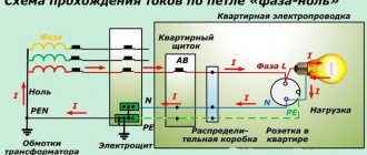
Construction of household electrical networks
Before embarking on such a responsible operation as identifying a phase wire, it is necessary to understand very well the structure of the household electrical network.
Unlike the networks through which electrical energy is transferred from power plants to the transformer, the voltage in a residential building or apartment is only 220 volts, but even this voltage can be dangerous to life and health, and can also cause a fire due to a short circuit.
Therefore, you can work with electricity only if you follow safety regulations.
A household electrical network, as a rule, consists of a three-wire wire:
- "Phase".
- "Zero".
- Grounding.
Let's now look at each in more detail.
What is a "phase"?
A “phase” or phase wire is the conductor that carries electricity into the house from the electricity supplier. It differs from other cable cores in the presence of a voltage of 220 V. But to operate an electrical device or equipment, a phase wire alone is not enough.
Just as a finger-type battery cannot provide electricity to any device connected with only one pole, so a phase wire needs another conductor whose name is “zero”.
What is zero and how to define it?
“Zero” is a conductor that stretches from the power plant generator to consumers, and although there is practically no electric current in it, it is a full participant in the relationship of transmitting electric current through metal wires.
Determining zero is not at all difficult. You can use a multimeter or tester for this purpose. If measurements are carried out using a multimeter, then it is necessary to connect one of the probes to some grounded object, and the other one in turn to the wires, when the device shows a voltage of 2 - 3 V. then the wire to which the probe was connected at the moment is zero .
A metal radiator of a heating system can act as a grounded conductor during the period when it contains liquid under pressure.
What is grounding?
Unlike “phase” and “zero,” grounding, so to speak, is local. Grounding is a conductor that is connected to the ground directly at the location of the house, and serves to prevent electric shock to a person in the event of a breakdown of the insulation of a phase wire on the device body.
How to distinguish phase and zero from each other?
In order to distinguish the “phase” from other wires, you can use a tool such as an indicator screwdriver.
If you touch the metal part of the wire with the tip of this screwdriver while holding the opposite end with your index finger, the indicator will light up if there is a phase wire. You can also determine the “phase” using a multimeter.
To do this, you need to turn on the device in AC measurement mode.
Set the maximum possible voltage on the device. The negative probe must be connected to some grounded object, for example, to a heating radiator, and the other one must be alternately connected to the conductors.
When the device shows a voltage that is approximately 220 V, then the conductor to which you connected is the phase wire.
How to determine “phase” and “zero” without measuring instruments
In order to detect the phase, you can use a time-tested, very simple and inexpensive method.
Using an ordinary incandescent lamp socket, it is easy to determine the “zero” - “phase” pair. You need to take a cartridge and connect the two wires that come from it alternately to the wires with the supposed phase and neutral wires.
When the light comes on, it will mean that one of the connected wires is phase. Now all that remains is to find out which one it is. It is very easy to do this if the RCD system is turned on in the electrical network. In this case, if you connect the lamp socket with one end to the third wire, which in this case is grounding, and the other alternately to other conductors.
At the moment when an automatic power outage occurs, it will mean that the second wire to which you connected the multimeter probe is a “phase”. Accordingly, the third conductor will be “zero”.
Advice
If there is no RCD, then after determining the “phase” - “zero” pair, one wire should be connected to ground, and the second will slightly spark when in contact with the “phase”.
Misconceptions that may arise when identifying a phase wire.
These are not entirely misconceptions, it’s just that if you follow this method of determining the phase, you can incorrectly conclude where exactly it is located.
Method for determining phase by wire color
If the workers who installed the wiring did everything correctly, then the phase wire should be black or brown.
But you cannot completely rely on this method of determining the phase, since it is possible that when connecting, the wires were simply mixed up. And instead of a black phase wire there will be “ground” or “zero”.
In conclusion, it is worth noting that it is worth doing independent electrical work only if you are very well versed in what you are doing, otherwise you should contact specialists who will carry out the wiring installation work efficiently and on time.
Source: https://okarkase.ru/kommunikacii/elektrichestvo/kak-opredelit-nol-i-fazu-samye-bystrye-sposoby.html