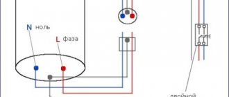
Each house or apartment requires a connection to the power supply, which is carried out through the installation of distribution boxes. For the purpose of safety and electricity metering, various modules are installed in the panels - control devices, automatic devices and other protective shutdown devices. There are many different options for how you can connect a circuit breaker to an electrical panel circuit.
How to connect a machine in a panel without errors
Modern electrical distribution panels are equipped with various metering and protection modules. These are protective shutdown systems, various relays, circuit breakers and multifunctional machines. Often they are connected incorrectly, as a result of which the functionality of the entire device is disrupted.
During maintenance of switchboards, violations of the installation of third-party modules were repeatedly observed, leading to instability of the system. Connecting automatic devices does not require special knowledge, especially since many are equipped with instructions or a connection diagram. Theoretically, electricians know how to correctly connect a machine in an electrical panel, but in practice, due to inattention or haste, they often make mistakes.
Connecting machines in the panel with an entrance from above or below
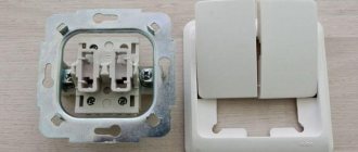
Before connecting the machine from above or below, it is recommended to inspect the connecting sockets. Automatic shutdown modules have one or more pairs of connecting contacts. Some are fixed, others are mobile, which often leads to confusion. According to paragraph 3.1.6 of the rules for installing electrical equipment, when switched on one side, the circuit must be connected to the distribution box to the fixed contacts.
This condition applies to both the connection of machines and third-party protection modules. There are sometimes exceptions depending on the brand, date of manufacture and other technical factors. In order to correctly mount the machine in the shield with your own hands, you need to figure out where the moving and fixed contacts are located.
Using the example of AB series BA47-29, manufactured by Iek, you can make sure that the upper contact is fixed, respectively, the lower one will be movable. This is determined by the markings on the toggle switch itself. Many manufacturers have identical terminal arrangements. A symbol is installed on them, confirming the purpose and location of the connecting terminals. Similar manufacturers are Schneider Electric and Hager.
RCD devices are designed to prevent short circuits or circuit overloads. If there is a threat of power surges, a special disconnector located inside the unit is triggered. Its action is based on thermal or electromagnetic induction. It does not matter which terminal the phase is connected to. Therefore, turning on the machine from above or below does not make a significant difference, and in both cases it will turn off.
Open and closed wiring
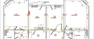
The difference between the methods is noticeable to the naked eye. The closed wiring is located inside the wall, for which grooves (grooves) are punched or cut into it, in which the connecting wire is hidden under a layer of putty. Open wiring is laid along the surface of the wall, on which it is held in special fasteners or laid in plastic guides - cable channels.
Accordingly, if you can see the wires that fit into the outlet, then the wiring is of an open type. Otherwise, closed wiring is used, for the installation of which the walls were cut.
These two methods of connecting an outlet can be combined with each other - if the old points are connected in a closed way, then nothing prevents you from connecting a new one in an open way. There is only one choice - in wooden houses the socket can be connected exclusively in an open way, just like all other electrical wiring.
Open wiring - advantages and disadvantages
An analogy with the most common extension cord (surge protector), which is essentially an additional branch of the electrical network, but is connected not to a junction box, but to an outlet, will help you understand why open wiring is good.
Advantages:
- You don't have to cut the wall to install a new outlet. This is especially true for those premises that have already been renovated.
- Installation does not require tools such as a wall chaser or a hammer drill.
- In the event of a breakdown, you don’t have to open the wall - all the wiring is in front of your eyes.
- Installation speed. Even after all the work has been completed, adding another point to the existing wiring is a matter of several minutes.
- If desired, you can quickly completely change the wiring - ideal for temporary connection schemes.
Flaws:
- There is a high probability of external influence on the wiring - children, pets, you can simply accidentally hook it. This disadvantage is mitigated by laying wires in cable channels.
- Exposed wires spoil the entire interior of the room. True, it all depends on the design abilities of the owner of the room - cable channels will fit perfectly into modern design solutions, and if the room is made in a retro style, then special wires and other accessories are produced for this.
- The need to purchase special fasteners, even if cable ducts are not used - in wooden houses, open wiring should be laid at a distance of 0.5-1 cm from the wall surface. Wires are often laid inside iron pipes - all these requirements are aimed at increasing the safety of using open electrical wiring.
As a result, this connection method justifies itself if for some reason there is no point in laying the wires to the outlet inside the wall. Besides the fact that the wiring will be visible, there will be no differences in the operation of the outlet.
Hidden wiring - pros and cons
Despite some significant disadvantages, it is used almost everywhere - the advantages of its use still outweigh.
Advantages:
- The wires to the socket fit into the wall, so wallpaper or other finishing can be done freely on the outside.
- Meets all fire safety requirements (in concrete buildings) - even if a short circuit occurs, there is no fear of a fire from the wires in the wall.
- There is a very low probability of damage to the wiring - it can only be damaged when drilling walls.
Flaws:
- For installation you need to cut the walls.
- It is difficult to carry out repair work.
- If the walls are finished, then after installing an additional outlet you will have to redo it.
The disadvantages are leveled out by preliminary calculations - if you plan in advance where and which block of sockets should be installed, then problems usually do not arise in the future.
Why is it not recommended to connect AV from below?
Some models from modern manufacturers allow circuit breakers in distribution boards to be connected to the lower terminals. They are equipped with special fixing rails or tires.
Such a connection to the machines in the panel will contradict the rules of the PUE, but does not prohibit connection to the lower contact. This rule works as a generally accepted procedure, thanks to which an experienced electrician understands that before servicing the electrical panel it is necessary to de-energize it. The first thing he will do is turn off the machine, assuming that the phase is on top. Consequently, after disconnection at the lower contacts and outgoing circuits, the voltage will turn off.
If we imagine a situation where the lower terminal is used to connect phase wires, by an electrician who did not consider it necessary to follow the connection rules according to the PUE. When it's time to replace the machine, another technician, out of habit, turns off the power to the top contact and tries to disconnect the machine by touching the bottom contacts with his bare hands. As a result, he receives an electric shock. That is why it is customary to comply with the rules established in the PUE.
Under the Union, all circuit breakers had one standard, which assumed the location of fixed terminals on top. Now, given the diversity and wide range of AVs from imported manufacturers, it is difficult to say where each contact is located. Some companies adhere to generally accepted rules, while others, on the contrary, try to diversify their products by introducing their own innovations.
At industrial enterprises, instead of conventional circuit breakers, switches are installed, the power of which is connected in accordance with all the rules of the Electrical Installation Regulations. If you do the opposite and turn the RB over, then its position will look unusual and even be uncomfortable. If you look with an experienced eye, you can immediately see the correct connection. If the switch is set correctly, then by turning it off, you can be sure that the lower contacts remain without voltage.
Is insulation coming into contact an error?
The most common mistake when installing a machine in an electrical panel is the presence of insulation that has gotten under the contact mount. It often happens that when installing circuit breakers or changing the box, after a while, the wiring inside it burns out. This happens when the ends of the wires are poorly stripped and particles of insulation get under the clamp, thereby worsening the tightness of the connection. In this regard, the insulating layer of the electrical wiring and insulation of the machine melts, which can cause a fire.
To avoid making such mistakes, it is necessary to thoroughly clean the ends of the wires connected to the automatic protection, and then make sure that there are no insulating particles left on the cleaned ends. After cleaning the insulation, form connections, tightening them well with a screw clamp.
Why can’t you connect several wires of different cross-sections to one terminal?
Sometimes there is a need to install several machines powered by one core, and for this it is advisable to use special rails or comb buses. However, they are rarely available, so you have to use ordinary jumpers - pieces of wires connecting the power to the AB.
This connection can be made in the shield with your own hands. To do this, you will need jumpers made of electrical wire with an identical cross-sectional area. To make a jumper, it is not necessary to cut, clean and connect each piece to each other. It is enough to measure the required length so that it is enough to combine all the AB contacts, and then, having given the required shape, strip the wire at the bends that are inserted into the terminals of the machines. Thus, a complete, continuous jumper emerges.
It is not recommended to connect machines using wires of different sections. When the ends are fixed in the terminals, the thick wires will be tightened well, and the wires of a smaller cross-section located nearby will be weakened. Subsequently, the sheath of wires and AB contacts will begin to melt at this point, which can cause a fire.
When installing an AB in an apartment or private house, use wiring with a cross-section of 2.5 mm2. This is determined by the load, the amount of energy expended, and also indicates how many amperes the machine should be set to.
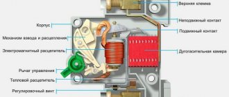
Design, principle of operation and types of introductory machines
Electrical line switching devices that provide protection against overloads and short-circuit currents are called circuit breakers. It is designed to ensure the safety of the power line in the event of an emergency.
This definition applies to all switching devices that are mounted in the electrical panel. The main difference between an input circuit breaker and a linear circuit breaker is that it has a higher rated current.
And it is calculated depending on the permitted power consumption of electricity. The input circuit breaker (IA) is the second stage of protection, used as a switching device. In the event of an overload or short circuit, the linear element must operate first.
VA has two degrees of protection:
- Overload protection. It is a bimetallic plate. When the permissible current is exceeded, it heats up. As a result, it bends and activates the thermal release mechanism. The greater the load, the more current flows through the plate. The heating rate increases. And the machine works faster. After disconnecting, you will not be able to turn on the device immediately. It takes time for the bimetallic plate to cool and return to its original position. Only after this can you put the device into operation.
- Short circuit protection. The machine has a current coil (solenoid). When there is a short circuit in the line, an instantaneous increase in current occurs. The solenoid retracts the core, the current protection is activated and turns off the power. The response time is a fraction of a second.
The VA is mounted before or after the electricity meter on a DIN rail. Depending on the supply voltage, they can be single-pole, two-pole, three-pole or four-pole. Bipolar ones are installed when connecting a single-phase voltage of 220 V.
Installed in apartments of multi-storey buildings. To provide electricity to cottages or private houses, three-phase voltage is supplied. To connect them, four-pole VAs are used. Previously, three-phase voltage was not connected; old houses were supplied with single-phase voltage.
The PUE prohibits the installation of single-pole circuit breakers as input switching systems. Due to the variation in response times, they cannot provide the necessary protection, which will lead to equipment damage or fire.
VA are characterized by:
- Rated current. A nominal value is applied to the device body at which the device can operate for a long time without shutting down, for example, C40. This means that the VA can handle up to 40 amps of current indefinitely. However, these readings are determined for an air temperature of 300C. At a lower temperature, the VA can withstand currents higher than the rated one. And at an increased temperature, the thermal protection operates at lower loads. This should be taken into account when choosing the location where the input panel will be installed;
- Number of poles. For single-phase voltage, two-pole devices are used, and for three-phase, four-pole devices. Some specialists install three-pole ones, which does not provide reliable protection;
- An important indicator is the time it takes for the machine to operate. When overloaded, this time can vary from several tens of minutes to several seconds. This depends on the amount of current flowing through the bimetallic strip. Short circuit protection is activated in a fraction of a second.
All installed devices must be consistent in current. For example, if the meter indicates a current of 40 A, then the VA must be rated for a current of less than 40 amperes. And linear devices in total should not exceed the current VA.
If the load is small, then a meter is installed, and then an automatic machine. When calculating, pay attention to the starting load currents.
The machines are divided into three subgroups B, C, D:
- B - these are the most “delicate” devices. Allows loads with inrush currents not exceeding 3-5 rated values indicated on VA;
- C - common machines installed in private houses and apartments. The excess inrush current varies from 5 to 10 times the nominal value;
- D – used in networks with high inrush currents and short-term overloads. The excess is 10-20 times the nominal value.
Installation
Before installing protective devices, it is necessary to determine in advance how many wires can be connected to the machine, how the supply wires will be connected, and only after that think about connecting the circuit breaker to the electrical circuit. If there is any doubt, it is better to refer to the basics of electrical installation. They describe in detail how to correctly connect circuit breakers in an electrical panel, prepare wires and carry out maintenance of electrical panels.
To install the machine in the electrical panel, you will need some tools and materials.:
- Cables of the same cross-section for the main circuit and jumpers when installing several circuit breakers.
- Insulating tape.
- Knife for removing insulation from ends.
- Screwdrivers of various types - Phillips or slotted.
- Devices for determining phase - indicator or multimeter.
- Pliers or regular wire cutters.
In order to understand what actions need to be performed in different situations, you need to consider different connection methods - single-pole and double-pole.
Automation must be on guard
Emergency switches, or switches, are the very first protectors of the electrical network from overheating. They perform three functions: in the latter case, they turn off all load consumers, and also trigger in the event of a critical voltage drop and short circuit.
Shields are purchased and come in different sizes. Therefore, after reading our article, you yourself will be able to calculate how many protective devices to buy a box for, you will find out which machine is triggered by what, and how to connect them. You will also learn that there are such methods of opening (releases) of the network during protection: thermal, magnetic and semiconductor.They are placed in the electrical panel, since there is not enough space for them near the meter. At the same time, consider how to properly connect the machines to each other.
It is important how you connect the machines with jumpers; they will be possible, but be sure to consult an electrician.
Single pole
For a single-pole connection, it is necessary to have a negative and power conductor. This method was used previously and was a unified standard, where the phase conductor was connected to the input contact AB, then passed through the output contact, went to the electric meter and was routed through the RCD. The neutral conductor is also powered by connecting through the meter.
Sometimes it is allowed to install the AV on the neutral conductor, although this contradicts the rules specified in the PUE, which says that the releases are installed when, when triggered, all conductors related to this circuit will be de-energized. Many people install two machines, one for plus, the other for minus. Therefore, it is worth considering whether it is necessary to set the machines to zero when there is a threat of equipment failure according to the description of the PUE.
Bipolar
With this connection of AV in single-phase networks, three types of conductor are used - grounding, power and neutral. The input contacts located on the top of the AB are marked with odd numbers, and the output with even numbers.
The supply wire is connected to input 1, after which it is tightly clamped into the terminal. The neutral, suitable for terminal 3, is connected in an identical way. Then the power core is passed through the meter and distributed evenly across all groups of switches. From pin 4, the yellow-green wire is connected to the ground bus by passing through the three-phase reading and protection blocks.
Is it possible to place an introductory machine in front of the counter?
The answer to this question can be found in the operating rules for electrical installations. Where in paragraph 7.1.64 it is said that it is necessary to provide a switching device that removes voltage from the electricity meter.
This is necessary when it fails or when replacing an old electric meter with a new one. That is, the PUE requires that switching devices be installed upstream of the meter.
Until recently, package switches were used for disconnection. But they did not provide the necessary level of security. Therefore, automatic switches are now being installed.
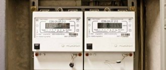
Boxes are available for sale in which a counter with automatic machines has already been installed. However, it should be taken into account that the VA, if it is mounted in front of the metering device, and the electric meter must be sealed. Violation of the seal by the home owner will result in a fine being imposed on him.
The PUE does not give clear instructions on where to place the VA - before or after the counter. But to ensure protection of the wiring of a house or cottage from overvoltage or other unfavorable factors, it is recommended to install the circuit breaker before the electric meter. Lightning protection is installed in the box along with it.
Read how to install an electricity meter.
Installation is carried out in a separate box, which is sealed by the controlling organization. To ensure reliable protection of the power line of a house or apartment, a common circuit breaker should be installed after the meter.
Features of connection diagrams
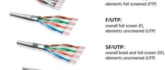
To connect houses to the electrical network, self-supporting insulated wires are usually used, extending from overhead power lines. Despite the advantageous characteristics of SIPs, it is not recommended to connect them and install machines directly. This is explained by the fact that during long-term operation the aluminum conductors begin to overheat. In this case, the insulating layer melts, leading to fire or malfunction of the AV.
To avoid such cases, use special adapters connecting copper and aluminum wires. This circuit for connecting the machines will secure further maintenance of the electrical panel and increase the operational period of the RCD.
Based on the above, we can say that the installation of machines is not particularly difficult, so it can be done independently. The main thing is not to forget the basic rules for connecting AV: use conductors of the same cross-section, do not place the machine on the neutral conductor and make the connection in accordance with the PUE. It is also worth considering common mistakes and observing safety precautions when working with electric current.
What to do first
You bought a certain number of wires from the network of a new house, completed the wiring, its ends are connected to a control panel that has not yet been built into the wall, and there are automatic machines nearby. Remember: it is better to install one automatic packetizer or RCD at the entrance to the electric meter. There is no such thing as too much protection. Next, make a plan for connecting the wires to the arranged packages.
It is advisable to relieve the network by dividing it into zones - with heavy loads and normal ones: kitchen, living room-bedroom, corridor-toilet, veranda-basement. You will get confused with packets; the instructions for them describe currents, loads, and wiring cross-sections. Methods of contact with terminals and so on.
What is a pulse relay: principle of operation, types, description of devices and connection diagrams. 155 photos of pulse-type relays and video installation instructionsPhoto relay for street lighting - selection criteria, tips for connecting and placing the device (135 photos)
Pulse protection device: classification, limiter connection diagram and tips for choosing a device (155 photos)