For entry into the house in 90% of cases, SIP with a cross section of 16mm2 is used. It would seem easier to take a corresponding 16mm2 aluminum lug (since SIP is an aluminum wire), crimp it and connect it. However, when entering a house, modular equipment is almost always used. And for its contacts, such 16mm2 tips are simply not suitable in terms of overall dimensions.
There are other brands of lugs that at first glance could ideally suit these needs, but there is one problem with them - they are all designed for copper conductors.
The most ideal and correct solution here would be to switch to copper on the facade of the house, even before entering the switchboard.
How to do this in detail can be found in the article Connecting SIP wires to a copper cable.
Never run a self-supporting wire directly into the house. SIP, if it is not Ng brand, is a flammable material. Therefore, it is imperative to make the transition from aluminum to copper outside the home. And only then use a copper cable to pull the wires to the distribution boxes or panel.
But what to do if the connection on the facade through piercing clamps does not suit you for some reason, or the energy supply organization absolutely requires a solid input directly from the support to the metering cabinet.
In this case, there are several options for connection. Let's consider them separately.
- ⚡
direct connection of SIP to a regular machine without any work with wires and lugs - ⚡
connecting an SIP to a circuit breaker with changing the contact surface of the bare core - ⚡
connecting SIP to a load switch or circuit breaker with a semicircular clamping bar - ⚡
connection using sleeves - ⚡
SIP connection via contact terminals
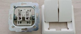
Direct connection to a regular machine
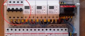
This connection has a right to life and most electricians perform it this way. The contacts of the machines are tinned and allow the connection of both copper and aluminum conductors. Here, for example, is the official response from ABB to the possibility of connecting aluminum wires to their equipment, specifically to modular automatic machines. However, it is worth noting that we are not talking specifically about SIP, but simply an aluminum wire (taken from here).
Many have already made such a connection and subsequently encountered the following (reviews from forumhouse.ru):
Due to the multi-core structure of the SIP wire, when it is clamped in a regular contact of the machine, not all the wires are used, but only a small contact area of the possible one is used.
Below is a photo of a real SIP after it has been clamped in the machine; pay attention to only two cores clamped by the contact surface (in addition, they are also crushed due to non-compliance with the clamping force).
As a result, after a couple of years, the contact begins to heat up and burn, and the SIP insulation melts.
In just a year, the screw of such a contact can be safely tightened at least a quarter of a turn. If this is not done, the circuit breaker itself will eventually burn out completely, and then it will need to be replaced.
It’s good if you have a spare SIP, since the burnt area has to be bitten out, cleaned and started again. The problem can be partially solved if you periodically, at least a couple of times a year, tighten the contact automatically. But this is not always possible.
Thus, energy supply organizations force them to seal either the entire metering cabinet with the machine and the meter, or they put a protective cover on the machine, which also ends up under the seal. And accordingly, you will no longer have access to the switch contacts.
Another disadvantage is that if you suddenly have a SIP with a cross-section not of 16 mm2, but 35 or all 50 mm2 (there was simply no other available), then it simply will not fit into modular circuit breakers up to 40A. Most of them are usually designed for a cross-section of input conductors up to a maximum of 25mm2.
Rules and procedure for the construction of VLI
The construction of overhead lines is carried out by a specially trained team of electricians. Installation begins with preparatory work, including clearing the route from vegetation and other obstacles. Before rolling out the wires, all supports must be installed, passages through engineering structures must be protected, and, of course, drums with the wire itself must be delivered. If VLI is supposed to supply electricity to the house, anchors must be installed on the building in advance for hanging SIP wires.
Installation of the drum and auxiliary mechanisms
Wire rolling begins by installing the drum. It is placed near the support where the final adjustment of the booms will be made. Moreover, the optimal distance between them is considered equal to the height of the support itself.
For manual rolling of wires, a special leader rope is used. This is a kind of synthetic cable with a length of 30 to 50 m and a diameter of 10 mm. The rolling out of the rope is carried out simultaneously with the fastening of the rollers and intermediate hangers on the supports. As the rope rises, the intermediate suspension is fixed to the pole with a special metal tape. If the support is equipped with a hole, the suspension can be secured using a bolted connection.
The intermediate suspension bracket is equipped with a hole. The rolling roller is attached here. The number of hangers and rollers depends on the number of complex pillars, intermediate, corner and anchor supports. It is important to maintain the correct position of the rollers so that the axis of the cable being laid is at the level of the recess of the support clamp.
The videos have some differences.
- The RT 5 mechanism is installed on complex and anchor poles. They are secured with a belt;
- The RT 2 mechanism is designed for intermediate supports. They are attached to the hole in the intermediate suspension bracket.
After completing the installation of all mechanisms, the leader cable is connected to the end of the SIP wire. To connect the cable and cable together, use metal stockings with a swivel. Moreover, stockings differ in purpose. At the same time, a mechanism is used that is put on the cable itself and the neutral core, and the entire harness is crimped with a synthetic stocking. A double bandage made of electrical tape helps to increase the reliability of the connection. The main stocking is equipped with a weight ring. The leader rope is attached to it.
Manually rolling out wire between supports
Manual rolling of SIP wires is carried out in sections limited to 100 m or between spans up to 50 m. The team performs the work in the following order:
- When everything is prepared for work, the team is divided into 3 units. The first and second links each include one electrician. Their duty is to monitor the operation of the unwinding mechanism motor, the uniform winding of the rope onto the reel and the smooth rotation of the wire drum. The third link monitors the passage of the connecting node of the rope with the cable along the unrolling rollers.
- The rolling continues until the connecting knot passes through all the posts and approaches the reel itself with a fully wound leader rope. At this time, a command to stop the engine is given. The cable is fixed to the anchor post with a nylon cable, after which the connecting unit is disconnected. A free piece of cable is left at the end supports for subsequent connections.
When rolling out the SIP wire, it is important to monitor its passage on the corner supports and prevent the sagging cable from rubbing against the ground.
Fixation and tension of SIP
SIP fastening is first carried out on the anchor supports of the span. Here the cable is fixed using anchor clamps. Next, the SIP is fixed to the intermediate posts. The tension of the neutral core is carried out according to the installation tables, but not more than 5% of the force of the design values. The sag of the arrows is determined visually, after which they are left to sag a little.
The next shift crew begins adjusting the booms:
- On the first anchor support, the clamp is installed on the zero core. A plastic clamp is placed near the clamp on the entire wire harness. It will not allow the tourniquet to unwind.
- The next clamp is placed on the final support bracket. A dynamometer is fixed to the load-bearing core away from the pole with a clamp. The cable of a hand winch, which is pre-attached to the first pillar of the span, is attached to it.
- While pulling the SIP wire towards you with a winch, look at the force on the dynamometer. When the desired value is reached, the zero core is fixed with a clamp on the bracket of the final support.
Read also: Socket welding of polypropylene pipes
The wire tension is completed, all that remains is to tighten all the wires with a clamp and unhook the winch.
Changing the contact surface of the core
Another option is to strip the SIP core with a small margin. Then, using pliers, twist the end of the exposed core even further, creating, as it were, one whole of many cores. This results in a smoother, more twisted section of the veins. And connect it directly to the contact of the modular machine.
In an automatic machine, such twisting does not separate into separate wires and the contact seems to improve. But again, in terms of useful compression area, this method is not the best. And if you use the load to the maximum, then after a certain time, although longer than in the first option, the contacts will still have to be tightened.
You can simply, without even bothering, screw a separate 2.5 mm2 core bandage onto a bare area and put it into the machine.
But in this way you will at least double the contact resistance, weaken the contact force exerted directly on the wire, and will not ensure its sealing.
Application of SIP
Completely eliminates the possibility of cable twisting during strong gusts of wind. The wire does not oxidize at the points of fastening and connection. The likelihood of emergency situations is minimal.
During installation, it is necessary to use a wire according to the voltage in the network and the expected load. The SIP is held on the support using a bandage hook. The hook is mounted on the pole using bandage tape. On the wall of the building, another fitting is used, a wall hook with fastening anchor bolts. It is necessary to ensure that the SIP is in good working order. We measure the insulation resistance with an Ohmmeter; we measure the serviceability of the cores and the absence of a short circuit with a multimeter.
In addition, each electrician must have certain uniforms and equipment:
- Canvas or leather mittens
- Dielectric gloves
- Voltage indicator
- Set of tools isolated
- Rope
- Separate wedges
- Montersky belt
- Clamp holder
- Block
- Insulated electrician's knife
Connection to load switch
This method is applicable even at the initial stage of installation work when purchasing materials. Instead of an introductory machine, it is worth purchasing a load switch. Why they are better than automatic switches can be found in the article Modular load switch - differences from a circuit breaker.
The fact is that most modular load switches have special contacts in which the clamping bar is not flat, but semicircular. It is this form of the contact surface that perfectly grips the SIP, without crushing it, and providing a sufficient useful contact area. There are also machines with a similar shape of clamping terminals (usually expensive and well-known brands), so pay attention to this in the store.
The reliability of the aluminum contact in the machine terminal will be further increased by the use of SuperCont lubricant. By lubricating the SIP core with it once and tightening the contact, the contact resistance, according to manufacturers, will remain unchanged for several years. This means no heating and no need to periodically tighten the contact. This is achieved due to the fact that the lubricant contains up to 70 percent copper.
How to install a SIP cable from the support to the panel
Electrical overhead lines (OHLs) are now mainly built using insulated self-supporting wire. Its distinctive feature is the presence of surface insulation made of thermoplastic or cross-linked lightproof polyethylene, which makes the operation of lines and bends safer.
Let's look at how SIP installation is carried out as part of the arrangement of electricity input into the building.
Inserting wires into a residential building Source izion.pro
Structural differences of SIP
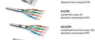
In networks with voltages up to 1 kV, only two types of insulated wires are used, although there are more of them. To understand what the difference is between them, we have provided a small informational list:
SIP – 1 Source 1sip-kabel.ru
- SIP-1 is a bundle of twisted phase wires with insulation and one uninsulated neutral conductor made of high-strength ABE alloy. Has from one to four conductive cores.
SIP – 2 Source provodok.site
- A distinctive feature of SIP-2 is the presence of insulation not only on the phase wires, but also on the neutral core, and naturally, it has a higher cost. That is why it is used mainly on high-voltage lines.
SIP – 4 Source promkabel.org
- This type of wire has at least two current-carrying wires, but it does not have a carrier (zero) wire. It is designed specifically for making branches from power lines towards buildings and laying along walls.
Note! Other types of SIP differ from each other not only in the type of insulation, but also in the number of cores. However, to carry out electrical inputs into the house, only SIP-1 and SIP-4 are most often used - the rest are intended for lines with voltages up to 35 kV.
Due to the presence of insulation, the SIP wire has an aesthetic appearance. This is, of course, an important nuance - but more for the consumer. Energy supply organizations value SIP because the insulation does not allow for “throwing” onto the wire, and thus using the resource bypassing metering devices. Another advantage is that the sheath makes it possible to connect two wires to each other without removing the voltage from them - however, this requires special fittings.
Next, let's look at how to connect the SIP cable to each other and perform any other manipulations with it.
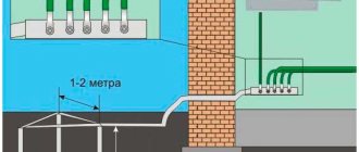
Diversion of SIP from overhead lines to the house
In order to connect a SIP wire from a pole to a house, you need to accurately measure the distance to the nearest support. If it exceeds 25 meters, you will have to install an additional power pole - perhaps right in the yard.
Maximum distance to the nearest pole Source fs137.myvi.tv
If the standard is met, you can lay the wire directly from the street support. Let's figure out what is needed for this.
To carry out installation work, the following fittings are required:
Branch (piercing) clamp with protective cap Source static-eu.insales.ru
- The number of clamps corresponds to the number of current-carrying cores of the wire.
Anchor clamp Source must.su
- To install a SIP cable from a pole to a house, you need 2 clamps, and two more for an additional branch support, if one is installed.
Steel fastening tape (bandage) Source kvt-pro.ru
- A galvanized steel tape is used to secure the SIP to the power line pole. One support requires 1 meter of tape.
Book clip Source infoyar.ru
- Reinforced clamps (buckles) are used to fix the steel bandage. There are 2 pieces per bracket.
Bracket Source dixi-st.com Catalog of flat roof house projects
- To secure the branch wire to the support, you will need 2 or 4 brackets. They are attached to the pole with tape, and to the facade of the building with anchors.
Strap (tightening clamp) Source svetelektro.net
- It takes 5 straps to make one connection.
Fastening Source stofasadov.ru
- Fastening SIP to the wall of a building is carried out using this simple device. Installed at 70 cm intervals, so the quantity is calculated based on the total length of the input.
Process in action
Now let’s illustrate how all this comes together into a single structure.
Installing anchors and pulling wires
It is impossible to drill an electrical support, so to install the brackets, not anchor bolts are used here, but bandage tape. It is wrapped in two rows around the post and secured with paper clips (buckles).
Attaching the bracket to the pole using tape Source .com
- Then the wedge, which is shown in the photo with a red arrow, is removed from the anchor clamp, the wire is pulled through it and the wedge is inserted back.
Pulling the wire through the anchor clamp Source .com
- Now, using the clamp fork, the wire is fixed to the bracket.
Installation of SIP on supports using an anchor clamp Source .com
- To connect to an overhead line, you need to install branch clamps with one side on the main wire, and the other on the wire that will go to the house. The arrow in the picture shows the central bolt. It must be tightened with a spanner until it comes off.
Connecting the machine to the SIP using sleeves
As mentioned earlier, standard aluminum lugs with pin contacts are not available. Different manufacturers have only those designed for copper wires. But there is a large selection of aluminum sleeves. And with some skill and some modifications, we can easily obtain the shape of the contact surface we need.
Take an ordinary standard connecting sleeve of 16mm2.
The sleeve is sawn in half. Three centimeters is enough to make good contact. It is then clamped in a vice and one of its ends is flattened. A design is made like a flat tip.
Next, this flattened end in the form of a spatula needs to be ground off. You can do this using sandpaper, a grinder disc, or just a file. A surface is created as close as possible to the pin contact for the circuit breaker.
It is advisable to make it so that it fits into different types of machines.
After all the preparatory work, the tip is inserted into the SIP and crimped with a hydraulic press. To ensure the tightness of the SIP at the point of contact, this entire structure is protected by a heat-insulating tube with a diameter of 10 mm. It is necessary to insulate with a tube, otherwise the gap between the sleeves, which are also exposed at the entrance to the machine, will be too small. This pin contact can be attached to any type of circuit breaker. Even to the connection points of comb busbars.
Well, in order to connect the SIP to the machine once and forget about this contact, it is better to buy a special adapter sleeve from aluminum to copper.
Press the SIP into the aluminum part, and do the same with the copper side as described above.
Then the copper pin contact will be clamped in the machine and you will not be afraid of any fluidity of the material with subsequent weakening of the contact surface. In this case, it is better to first insert a monocore of the appropriate cross-section into the copper part of the sleeve and clamp it all with a press.
Then again cut off the excess, grind it in a vice and the transition contact is ready.
When you don’t want to resharpen the sleeves, you can use them for their intended purpose. Just make a connection between a copper monocore and an aluminum SIP directly in the cabinet. Naturally, with subsequent insulation of the entire structure with a tube HERE.
All that remains is to buy a 2x16 SIP wire and the necessary materials for its installation:
- SIP wire 2x16 is an aluminum self-supporting insulated wire, consisting of two cores with a cross-section of 16 mm 2, 25 meters long.
- Two anchor clamps , one will hold the 2x16 SIP wire to the house by a hook in the wall of the house, and the other 2x16 SIP wire on the support.
- Two branch piercing clamps connecting the 2x6 copper cable connected to the electric meter in the panel, and the 2x16 SIP wire from the power line support (transition from aluminum to copper).
- The hook on the wall , on which the 2x16 SIP wire will be secured to the house using an anchor clamp, was made independently. We bent a piece of reinforcement with a diameter of 10 mm into a semicircle and welded it to a 150x200 mm plate, which was screwed to the wall of the house with 6 self-tapping screws 80 mm long.
You can also buy ready-made hooks for installing anchor clamps. The photo shows mounting hooks for SIP 2x16, manufacturer KVT.
I drilled a wooden wall of the house with a wood drill (feather) with a diameter of 24 mm, and brought out the corrugated copper cable from the electrical panel to the street. But…. correctly remove wires and cables from the wall of the house through a metal pipe . Why the hole to the street to connect the 2x6 copper cable and the 2x16 SIP wire was drilled here was explained in the article “How to assemble an electrical panel with your own hands.”
After about 45 days, electricians arrived, disconnected the power lines and replaced the old wires to the house with a new 2x16 SIP wire. According to the rules, the electric network company was supposed to replace it with a new 2x16 SIP wire within no more than 30 calendar days, but somehow they and their neighbor could not connect at the same time, so everything went without mutual claims.
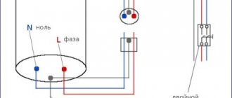
In order to correctly connect the 2x16 SIP wire on the support to a 0.4 kV power transmission line and in the house to the electric meter, it is necessary to correctly connect the 2x16 SIP phase wire to the phase wire on the overhead line support and the 2x16 SIP neutral wire to the neutral wire (PEN). The 2x16 SIP wires are marked with color, “red” is the 2x16 SIP phase wire, “blue” is the 2x16 SIP neutral wire, or the phase wire is regular black, and the neutral wire is marked in blue.
I didn’t like how they replaced the old electrical wiring with a 2x16 SIP wire, namely:
The aluminum wire SIP 2x16 and the copper cable 2x6 from the electrical panel were connected by twisting , which is prohibited by the PUE. Electricians referred to the fact that special branch piercing clamps often either “do not pierce” the wires or can “cut” the input wire to the house; in general, the result would be a bad connection of the wires. We wanted to directly connect a 2x16 SIP wire to the electric meter, but laying an aluminum 2x16 SIP wire with a cross-section of 16 mm 2 along the wall of the house and leading it into the electrical panel is also not a pleasant pleasure.
Read also: How to connect a switch with two wires
We left a large supply of 2x16 SIP on the wall of the house. Why is he needed like that? Moreover, on the support itself there is also a supply of SIP, which is wound around the VLI support.
Also, the 2x16 SIP wire from the power line support to the house is weakly stretched and sags a lot , this is better than if it were stretched like a string, but this is also bad.
I recommended to the neighbor to call them back, connect the 2x16 SIP wire and the 2x6 input copper cable to the electric meter using special punctures for 2x16 SIPs or nuts and pull the 2x16 SIP wire to the power line support, and for the neighbor, when the electricians arrive and turn off the power line, shorten the copper 2x6 cable to get rid of coils on the wall of the house.
For a three-phase connection , in principle, everything will be the same, only 2 times larger, i.e. four anchor and piercing clamps and 4x16 SIP.
Below is the correct transition from aluminum to copper and the entry of copper cable through a metal pipe into the house.
Thank you for your attention.
Selection and calculation of the introductory machine
To protect the input cable, we need to select a circuit breaker for input into the house, which is selected according to the rated current flowing through it when consumers are turned on. In order to determine the rated current of the input circuit breaker, it is necessary to calculate the total power of all consumers in the house. We have compiled a table showing the name and power of the consumer
But since consumers cannot all be turned on at the same time, the demand coefficient is used for calculations, which is equal to 0.7 when the number of receivers in the room is from 5 to 200.
Using the formula, we determine the estimated total active power of consumers:
Calculation of active power of all consumers
Next, you need to calculate the total total power of consumers in the house using the following formula:
Calculation of the total power of all consumers
where cos phi is the power factor, for residential premises it lies in the range of 0.96 - 0.98.
Now we determine the calculated current for a single-phase network using the following formula
Rated current calculation
where Unom is the rated voltage of a single-phase network equal to 220 V
Now, based on the calculated current, we select the rating of the input circuit breaker. For internal power supply of apartments and houses, modular circuit breakers of standard ratings are used:
6, 10, 16, 25, 32, 40, 50, 63 A
The rated current of the machine must be equal to or the nearest greater from the standard range.
In our case, for an introductory machine, we need a machine with a rated current of 32 A
Selection and calculation of input cable
The aluminum cable AVVG 2x10 mm2 was mentioned above, perhaps you were wondering where the figure came from? Everything is very simple, before purchasing we made a preliminary calculation of this conductor.
The cross-section of the cable for entry into the house is calculated based on the maximum permissible current at which heating of the conductor will not cause damage to the insulation of the input cable.
Those. our cable must withstand the current for a long time at which the thermal release of the machine will operate.
The thermal release current is assumed to be 15-20% greater than the rated current of the machine and is calculated using the formula:
Calculation of thermal release current
Now from the PUE, in tables 1.3.4 for copper conductors and 1.3.5 for aluminum conductors, we select the required cross-section of the cable laid in one pipe from the “ one two-core ” column, equal to or the nearest larger.
Table 1.3.4. Permissible continuous current for wires and cords with rubber and polyvinyl chloride insulation with copper conductors
Table 1.3.5. Permissible continuous current for rubber and polyvinyl chloride insulated wires with aluminum conductors
According to the tables, cable cross-sections are suitable for us: 6 mm2 for a copper conductor and 10 mm2 for an aluminum conductor.