Basic terms
For a better understanding, let’s understand the basic terms, because this is important for the correct selection and installation of the grounding conductor.
Let's look at the basic definitions:
- Grounding is the connection of metal parts of an electrical installation or equipment to a grounding device. In other words, this is a set of measures aimed at increasing human safety when using electrical appliances.
- A grounding device is a group of elements that ensure the removal of voltage (potential) into the ground to protect a person from the negative effects of electric current. It consists of a grounding conductor and a wire or busbar connecting to a non-current-carrying part.
- Ground electrode is a structure consisting of several welded metal bars immersed in the ground to a certain depth to ensure rapid removal of potential. The main characteristic of the ground electrode is its resistance, which should not exceed 4 ohms.
- Grounding wire is a product that connects a metal non-current-carrying part of equipment to a ground electrode. Fixed by welding or bolting. The degree of safety directly depends on the correct choice of this part of the design.
- A grounding bus is an element of distribution boards designed to connect PE conductors, a neutral working wire and a ground electrode. The main difference from the wire is the design features that allow other grounding wires to be attached to the bus.
Today, the term “ground loop” is often used. This is the name of the ground electrode used in everyday life. This also means a structure consisting of several electrodes or metal corners located in the ground and mounted in the shape of a triangle. It is to this structure that the grounding busbar is connected.
If the device is not grounded
What possible accidents are we talking about and what needs to be grounded? If the device breaks down, dangerous voltage can enter its housing. What dangerous things can happen if the chassis is not grounded? If under these conditions a person comes into contact with the body of the device (for example, we can talk about a washing machine), he will receive an electric shock, because the human body has a finite electrical resistance, and through the floor and through surrounding objects he is somehow connected to the neutral wire of the network (which is usually grounded - solidly grounded neutral).
And since the current tends to close the circuit, it (the current), tending to the neutral wire (and to the ground) will flow through a person - this is an electric shock, which can be fatal. Therefore, to protect against such troubles, the housings of electrical devices are grounded - connected to the ground through a ground electrode.
Types and features of grounding
When purchasing a wire to connect to a grounding device, it is important to know the types of grounding and its purpose.
There are two types in total:
- Working. Purpose - to ensure normal operation of the electrical installation. Without this condition, the functioning of the network would be impossible for various reasons. In other words, this is the normal operating mode of the equipment. An example is grounding the neutral of power transformers in order to increase the short-circuit current and increase the sensitivity of relay protection.
- Protective. The task is to guarantee the safety of people from being exposed to electric current at home or when servicing equipment on overhead lines, substations or other electrical installations. Depending on the situation, it may be provided for protection against lightning, surge voltage and potential that may appear on the body of household or other equipment.
In apartments and private cottages, protective grounding is used, which we will discuss in more detail.
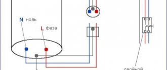
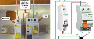
Grounding work together with RCD
Protective grounding is the primary protection against electric shock. But one precaution may not always be enough. For additional protection, a residual current device (RCD) is installed in the circuit. In technical terms, an RCD is a switching device designed to automatically disconnect a damaged device from the network when a leakage current appears.
It will be interesting➡ Direct current - definition and parameters
When the insulation inside an electrical appliance (be it a washing machine, a boiler, a computer, etc.) is damaged and a phase hits the grounded body, the current begins to flow into the ground. The RCD reacts to the flow of this current, which instantly trips and turns off the damaged device, thereby leaving the circuit without voltage. In appearance and operating principle, the RCD is similar to a regular machine. Only the machine protects the electrical circuit itself from high currents, and the RCD protects a person from being energized.
Grounding work in conjunction with an RCD.
The principle of construction and purpose of protective grounding
In simple terms, protective grounding is formed as follows. The ground wire is connected to a non-current-carrying metal part.
At the next stage, the “ground” connected to the equipment is combined, and then goes through a separate wire or busbar to the grounding device.
In the event of a voltage breakdown on a metal body and a person touches it, the potential goes through the ground and not through the body. Due to the low resistance, protection and RCDs operate faster.
In comparison, the R of a ground loop is only 4 ohms or less, and that of a human is more than 1000 ohms. According to Ohm's law, we know that current always follows the path of least resistance.
Thus, protective grounding is designed to solve the following problems:
- reducing the potential difference between the grounded device and other objects and protecting human life;
- draining current into the ground and increasing its values to trigger protective devices (RCDs, automatic devices).
Therefore, when laying a conductor for grounding, it is important to ensure the presence of protective devices. The latter must quickly respond to leakage or high currents by cutting off the damaged area. The sooner this happens, the better.
Why does it give an electric shock?
To understand why grounding is needed, first let’s figure out in what cases and why we are shocked. The main thing that is needed for the flow of electric current is a potential difference. This means that if you stand on the floor and grab a bare wire or other live part with your hands, the current will flow through your body and the floor into the ground. An alternating current of only 50 mA is already dangerous for humans. And if you grab the current-carrying part with both hands and hang on it without touching the ground, then most likely nothing will happen; of course, it’s not worth checking this.
The highest resistance of the grounding devices of overhead line supports.
Therefore, birds are not electrocuted on the wires. But let's get back to talking about grounding. As we have already said, the housings of electrical appliances are grounded. What is it for? Wiring and other equipment components, such as electric motors, heating elements, etc., in normal condition do not have phase contacts with the device body, metal hose or cable armor. But in the event of a malfunction, the phase may end up on the body. This can happen if the insulation of the windings of motors and transformers is damaged, the dielectric layer of heating elements is broken down, or the insulation of connecting wires inside the device and cable lines is damaged.
Grounding depth.
As a result, a dangerous potential will appear on the body, in simple terms: the body will be “under phase”. When you touch it while standing barefoot on a tile, concrete or even wooden floor, you will get an electric shock. In the worst case scenario, this can lead to death. Most often, this situation arises as a result of partial failure of the heating elements of washing machines, water heating tanks, and instantaneous heaters. And this is especially noticeable when you simultaneously touch the washing machine and water and heating pipes, or in the case of a water heating tank, when you take a shower or bath, it gives you an electric shock. The last problem can be solved by organizing a potential equalization system (grounding the bathtub and other metal parts of the water supply system).
If the body of a damaged device is grounded, dangerous voltage will flow to the ground and (or) a protective device will operate - a residual current device (RCD) or a residual current circuit breaker (DCB).
If the housing is zeroed, a regular machine will work, since this will be a short circuit to the housing (zero in this case). Difavtomats and RCDs determine current leakage by comparing the currents of the phase and neutral wires - if the current in the phase is greater than in zero, then the current flows into the ground, through the grounding wire or through the human body. Such devices are triggered by differential current (current difference) usually 10 mA or more.
It will be interesting➡ What is a bridge rectifier and how does it work?
Therefore, a modern electrical panel is a complex device with a large set of switching protective devices, and the presence of grounding is mandatory in all buildings built or renovated after 2003. That is, they must have 3-wire single-phase or 5-wire three-phase electrical wiring installed. If you want to express your opinion on grounding issues, write about it in the comments.
Grounding cross-section requirements
Many owners of houses and apartments are faced with the need to do grounding themselves. This is explained by the fact that in old buildings before 1998, there were no grounding connections and, accordingly, no busbars for connection at all.
Even if the house already has a grounding system, when choosing a wire, you need to find out the type of system.
Taking into account the PUE, four grounding schemes are distinguished:
- TN-S - use of neutral and separate conductor. The circuit is relevant for alternating voltage.
- TN-C - combining “0” and ground with a common wire. In this scheme, the neutral goes separately, which is typical for old buildings.
- TT - direct ground to electrical equipment.
- IT - connection to the housing using resistance or insulation of current-carrying conductors.
More about grounding systems, their advantages and disadvantages.
To choose the correct cross-section, it is important to consider one more point - the type of grounding.
It could be:
- stationary (done without the need to move, on an ongoing basis);
- portable (can be removed if necessary and moved to another object).
For domestic purposes, as a rule, the first option is used. It is this that we will focus on when choosing the section (S).
To avoid mistakes, follow these simple rules:
- For phase S up to 16 sq. mm grounding conductor is selected of a similar size.
- At S the phase has from 16 to 35 sq. mm cross-section of the “ground” conductor is selected to be 16 sq. mm.
- If S of the phase wire is over 35 sq. mm, the ground electrode must have a thickness of at least half this value.
Most often, copper wires with S equal to 4 square meters are tried on in a house or apartment. mm. Under such circumstances, S of the grounding wire is selected with the same parameter.
If, for example, the thickness of the phase suitable for the cabinet is 25 sq. mm, the optimal parameter S is 16 sq. mm. Everything is simple here, so there should be no confusion.
It is important to remember a number of more rules:
- For TN-C and TN-CS, the lower cross-section threshold is 10 square meters. mm for copper and 16 sq. mm for aluminum conductor.
- In an apartment or house, a wire with one core is sufficient.
- Color requirements: yellow-green.
Sometimes when calculating the grounding cross-section, a special formula is used. It takes into account the short-circuit current, protection response time, type of insulation, type of gasket and other features. In practice, this method is rarely used.
What is needed in the house
Electricity is an integral part of human life. It provides us with a comfortable life and makes it easier to do many things. But it should not be treated too carelessly, as electric shock can have serious consequences. Electrical injuries can occur not only due to ignorance and carelessness, but also due to malfunction of electrical appliances. In such cases, the metal casing may become energized and a person may be seriously injured if touched. Therefore, you need to pay attention to your grounding in a private house and apartment to protect yourself from injury.
Classification of electrical installations according to electrical safety measures.
It is to prevent such situations that there are special electrical safety rules that provide protective measures. These include grounding. It is connected as an additional conductor to the existing electrical wiring and connected to a ground electrode, which is mounted in the ground. In emergency situations, electric current will be discharged into the ground along this circuit.
Why do you need grounding in a house?
According to the rules for electrical installations, any electrical equipment with a voltage of 50 V in an AC network and 120 V in a DC network must be grounded. If equipment is installed in hazardous areas, grounding will also be required at lower voltages. After damage to the insulation of equipment, for example a washing machine, its body will be energized, which certainly poses a danger to those who touch it. However, if the housing is grounded (there is grounding in the house), the touch voltage due to the flow of current into the ground will be reduced to a safe value. The person who touches the st. The machine will only feel a slight tingling sensation.
With properly adjusted protection, the appearance of phase voltage on the grounded body of any device should lead to the disconnection of the circuit breaker or RCD in the electrical panel. Thus, grounding allows you to disconnect an electrical device from the network if a fault occurs that is dangerous to humans.
Ground wire color and connection features
To avoid confusion, it is important to understand what designations need to be provided for such wires.
Today the following types of markings are used:
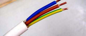
- PE - 0 protective wires and bars, colored in the form of intertwined yellow-green shades.
- N - 0th wires, indicated in blue (neutral).
- PEN - combination of zero and ground. The main part is blue, at the edges there is a combination of yellow and green colors.
In our case, a designation with the corresponding color design (yellow and green) is used. It is designated in the same way in a three-core wire.
If you don’t have a wire with the required color on hand, you can use regular yellow and green electrical tape. All that is required is to make marks on the ends of the wire.
Grounding (PE) is brought out and connected to the grounding bus, body or metal panel door. The neutral wire (N) is connected to the neutral busbar.
Read more about grounding and zeroing, what is the difference between them.
Marking
For a better understanding, let us raise the issue of marking the insulation of the conductors used.
The following symbols can be used in the wire name:
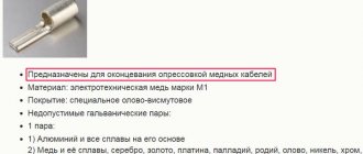
- A - aluminum core (in the absence of a letter - copper);
- AC - presence of lead braid;
- AA - stranded wire with an aluminum core and a braid of the same material;
- B - corrosion protection, made of double-layer steel;
- G - without shell;
- Bn - protection from moisture and resistance to fire;
- NP - non-flammable material;
- R - rubber shell;
- B - polyvinyl chloride shell;
- K - control cable, etc.
You must pay attention to the above markings when choosing a wire for grounding in relation to its cross-section (this was mentioned above).
Brands and requirements
When purchasing a grounding cable, you need to thoroughly examine it for the possibility of using it in a house, apartment or special room (for example, a bathroom, sauna, etc.).
The grounding conductor can be single-core or multi-core. Here you need to focus on the installation location and ease of use.
Here are some examples:
- When connecting the case to the cabinet door, it is necessary to maintain mobility, so it is better to use a multi-core product. If you install a single-core conductor, it will quickly become damaged due to frequent bending.
- To connect the body of an electric motor, where mobility is not needed, rigid conductors are useful. There are no special requirements for flexibility here.
- When arranging grounding in an apartment or house, you can use any type of wire, taking into account the risk of damage and ease of installation.
Depending on the type, the grounding conductor can be made of aluminum and copper, come as a separate product or as part of a cable coil, be with or without insulation.
Today there are several main brands of wires.
NYM
A product with a copper core and an intermediate shell of green-yellow color. It is easy to install and is used for voltages up to 660 V. Operating frequency 50 Hz.
The number of conductors can be from one to five with a cross-section from 1.5 to 6 square meters. mm. The rated current is determined by the working cross-section of the conductor.
Operating temperature range from -50 to +50 degrees Celsius. The bending radius is no more than four cable diameters.
Pros: resistance to moisture and fire, flexibility and a wide range of design options.
Cons: high price and fear of direct sunlight.
VVG
Cable with polyvinyl chloride insulation, outer PVC sheath and without a special protective layer (armor). It can be single or multi-core.
In 3, 4 and 5-core cables, grounding and neutral can be provided.
Allowed to be used as a grounding conductor at voltages up to 600 V.
Some types of cable are designed to operate at 1000-2500 V. Operating temperature ranges from -50 to +50 degrees Celsius.
PV3
Copper wire with polyvinyl chloride insulation. It is highly flexible, which allows it to be used for grounding various devices and mechanisms (including in everyday life).
The product is resistant to moisture and can operate in temperatures from +60 to -70 degrees Celsius. Therefore, it can be used even in extreme conditions - baths, bathrooms and outdoors.
PV3 is not afraid of mold and is not susceptible to fire. When exposed to high temperatures, normal melting of the shell occurs.
PV6
A reliable product used for laying live parts and grounding. During use, it is important to avoid direct sunlight and high temperatures.
The cores of the product consist of copper and can be single-wire or multi-wire. Operating voltage up to 1000 V.
Thanks to the use of transparent plastic, it is more convenient to monitor the health of the device.
Colors may vary, so color marking must be done independently. To do this, you can use the approach mentioned above - marking with yellow and green electrical tape.
ESUY
Highly flexible copper ground cable. The core is made of thin wires. There is a high strength braid on top. Organosilicon rubber is not used in production.
The product has high frost resistance, a transparent shell and an operating temperature range from -40 to +70 degrees Celsius.
The most popular brands of wires/cables for grounding are discussed above, but other options can also be used. The main thing is that the conductor meets the requirements of flexibility and cross-section.
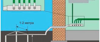
Types of ground loops
Any grounding device consists of a series of vertical rods buried in the ground so that their top is 0.5-0.7 m from the surface of the earth. They are connected by a horizontal ground electrode, which is also used to lead the circuit to the consumer. In private housing construction, closed or linear structures are used.
Why can't you get by with just 1 ground electrode?
It would seem that there is contact with the ground, which means that only one rod can be used. But this is not enough and is prohibited by the PUE.
There is such a thing as resistance to spreading. The maximum value of current density and voltage is around the immersed rod. When electricity passes through the earth, the resistance to its movement increases and at some distance becomes zero. This zone is called the spreading zone.
When installing 1 ground electrode, the spreading area is too small and does not ensure rapid current spreading, so at least 2-3 rods are used. Due to this, the short circuit voltage supplied to the ground electrode is quickly distributed, and the resistance of the device is reduced.
Closed loop
It consists of 3 or more rods connected at the top with a steel strip no less than 4 mm thick and immersed in the ground. It is connected to the main grounding bus by one conductor. Its cross-section is selected based on the total power of the devices, core material and degree of insulation. More details can be found in the PUE clause 1.7.76 and clause 1.7.77.
Linear
Can be used for one or a group of buildings. Vertical rods are connected to each other by a horizontal steel pipe or profile without closing the circuit.
Reticulate
The outer contour in this case is made of rods and horizontal connections in the form of a mesh. It is used for grounding powerful electrical installations, so it is not used in private homes.
Deep grounding system
According to the PUE, the distance between the pins must be no less than their length, therefore, when laying such bulky structures, it is necessary to dig multi-meter trenches. In an already landscaped area, this is not the best option, so modular deep systems are used to install more compact grounding.
The length of the ground electrode depends on the resistance requirements. In a house without gas heating, the requirements are softer, and a driving depth of 6-10 m is sufficient. If there is a gas boiler, they are immersed in the ground 10-15 m. Welding is not used; the electrodes are connected to each other by couplings. Driving is carried out with a powerful hammer drill or vibratory hammer.
Wires for grounding 380 Volts
When choosing a 380 V ground wire, it is important to adhere to the same requirements as discussed above. Pay attention to the type of insulation, cross-section, flexibility, operating temperature and other parameters. There are no special differences in requirements between grounding at 220 or 380 V.
If we talk about the type of wires used, it is recommended to use the brands already discussed above.
To these you can add a PVS 5x6 wire in double round insulation with five cores. Suitable for powering and grounding equipment up to 660 V.
What is better to buy for a private home and bathroom
Now let's look at how to choose a grounding wire for a specific installation location.
For home
When installing a grounding structure in a private house, take into account the cross-section of the wiring and the presence of a grounding loop. If the ground electrode is buried in the ground and the bus bar is removed, all that remains is to select the correct cable.
Please note the following points:
- Section. Must be selected taking into account operating conditions. In most cases, a wire of 4 sq.m. or more can be used for the home. mm and thicker.
- If a wire with a cross section of 6 square meters is used. mm without insulation, preference must be given to a stranded conductor.
- It is recommended to use steel reinforcement with a diameter of 16 square meters or more as grounding conductors. mm. It is allowed to use a steel angle of 50 mm or more.
- After completing the work, it is important to measure the resistance, which should not exceed 4 ohms.
When choosing a cable, you can use any of the ones suggested above - VVG, PV-6, NYM, ESUY, PPV and others.
Read - how to make grounding in a private house.
For bathroom
When it comes to the bathroom, it is important to ground all metal elements. This category includes the body of a metal bathtub, hot and cold water supply pipelines and other metal elements.
The cross-section of the ground wire must be at least 2.5 square meters. mm, but when using a thicker phase wire, it is necessary to use a “ground” of 4 square meters. mm.
Wires that are connected to metal elements can be brought out to a common busbar, and from there the wire can be directed to the panel or to the machines (there must be a grounding wire for a bolted connection).
The conductor used can be flexible or solid, depending on the installation characteristics. Here the decision is made on the spot.
An important point is the requirement for cable resistance to temperature and moisture. The above brands of wires fully comply with the required characteristics.
Grounding systems in a private house: types, differences and design features
Much has already been said about how important a properly installed grounding system is for a private house or cottage. Therefore, there is no particular need to repeat about the danger of electric shock in a house that is not connected to a ground loop. And if you want to ensure the maximum safety of your living space, then the information presented in this article will no doubt be useful to you.
Types of grounding for a private house
Depending on the design features of the power line approaching the house, various grounding systems are used. The following types are distinguished: TN-S, TN-C, TN-CS, TT, etc. Private houses and cottages are usually connected to two types of grounding systems: TN-C-S and TT. And if there is no grounding in your house, then these systems are the easiest to implement in practice; it is them that many craftsmen create on their own, and it is they that will be discussed in this article.
Let us briefly explain what the letters in the names of the systems mean:
- The first character indicates the grounding parameters of the power supply (T - ground, etc.).
- The second symbol (N or T) characterizes the grounding parameters of open parts of household electrical installations. The letter N, for example, denotes grounding or connection of the protective conductor of a home electrical installation with the neutral of the power source (transformer substation).
- The letters S and C indicate a subtype of system in which grounding is carried out through the power source.
Simply put, if the first letters in the designation are TN, then we are talking about a system with a solid grounding of the power source, and the consumer’s electrical system is connected to its neutral through neutral and protective conductors. As we have already said, grounding systems come in several varieties:
- TN-C is a system that has combined neutral and protective conductors. The supply line in this case consists of two- or four-core cables (phase and neutral conductors - in a single-phase power supply system, three phase and one neutral - in a three-phase power supply system). The TN-C system can hardly be called a full-fledged grounding system, because the grounding conductors of the electrical installation in it are connected to the neutral wire coming from the transformer. It is usually called grounding, because it is hardly capable of performing all the functions of a grounding loop.
- TN-S is a system that has separated neutral and protective conductors. The supply line in this case consists of three- or five-core cables (phase, neutral and protective conductors - in a single-phase power supply system, three phase plus neutral and protective conductors - in a three-phase power supply system).
- TN-CS is a system in which the neutral and protective conductor combines their functions only in a certain area, which begins near the power source and ends at the entrance to the house. Here they are divided into neutral protective (PE) and neutral working (N) wires (the protective conductor in such a system is re-grounded). In essence, the TN-CS system is created on the basis of the TN-C.
- TT is a system in which the home power supply system has a separate solid grounding, which is not connected in any way to the grounding of the supply substation.
Grounding in all TN category systems is carried out through a transformer substation, while the TT system involves the creation of a grounding loop directly near the house. One can argue for a long time about which of the two systems is better – TN-CS or TT, so let’s immediately outline the pitfalls of these two systems.
If you are thinking about creating a TN-CS system, then first of all you should make sure of the reliability of the power line supplying electricity to your home. After all, the condition of suburban power lines (and they are, in most cases, overhead) leaves much to be desired. No one can guarantee that one fine day, as a result of an accident on the line (if a flimsy support tilts under its weight, etc.), the exposed neutral wire will not connect to the phase wire. As a result, the zero will burn off from the transformer, and we will get a deadly voltage “walking” through the body of household electrical appliances.
AlexeyL FORUMHOUSE user
For the TN-CS circuit, you must either be completely confident in the safety and reliability of the PEN conductor coming to you on the street, or you must guarantee this safety with your own grounding. Given the typical state of local air networks, the only certainty is the opposite: the unreliability of PEN. And the construction of a grounding system capable of withstanding the zero current of many neighbors in the event of a broken neutral and a large imbalance of loads across phases is a very difficult and expensive task.
Let us explain: PEN is a combined working neutral (N) and protective neutral (PE) conductor connecting the transformer substation with the incoming home panel.
The use of SIP cable as part of the supply line provides some safety guarantees, but if the condition of the ground supports is unsatisfactory, all these guarantees can be called into question. Simply put, it is possible to create a TN-CS type grounding system only if you have full confidence in the reliability of the supply power line.
The TT system in a private house also has its disadvantages. Systems of the presented type require the mandatory presence of residual current devices (RCDs) or circuit breakers in the grounding circuit, which should be regularly checked for operability. To ensure safe operation, the CT must be equipped with potential equalization systems and an artificial grounding loop, the creation of which requires time, effort and certain costs.
In practice, creating a TN-CS system always looks more preferable, but if the condition of the current supply lines is questionable (the supply line is formed by bare conductors, there are frequent breaks, air supports are in poor condition, etc.) it is recommended to create a system as a more reliable alternative TT.
Briefly about the TN-S system
If a TN-S system is connected to the house, then it is enough to equip the input panel with a grounding bus, to which the PE input grounding conductor and protective conductors going to household consumers should be connected. The PE conductor can be connected to a repeated grounding circuit. We will return to the question of how to do this later.
AlexPetrowFORUMHOUSE user
With TN-S, a five-wire line with separate PE and N comes to the consumer. In such a system, nothing needs to be divided.
We are talking about separating the incoming neutral wire, which is supplied to the consumer in TN-C systems and is divided when creating a TN-CS system. A similar division is shown in the diagram.
TN-CS system design
If a TN-C system is suitable for your home, if you have verified that the supply line is in impeccable condition and have made sure that a SIP cable is used as the supply conductor, you can begin to create a TN-CS type grounding system.
The conductor is divided into the protective wire PE (yellow-green) and the neutral wire (blue) in the input panel.
In the shield, re-grounding is connected to the system.
In accordance with the updated edition of the PUE rules, the separation of the PEN conductor must be performed before the input switching protective device and before the electric meter. It is strictly forbidden to include protective and switching devices in the circuit of PEN and PE conductors. You can only break the circuit of conductor N (PUE 1.7.145).
AlexPetrow
Conductors PEN and PE are inseparable! All devices with switching (circuit breakers, circuit breakers, batchers, metering devices, etc.) must be located on the line of conductor N (it can be “torn”, and sometimes necessary).
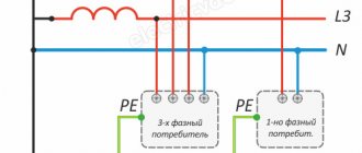
The PEN conductor is divided according to the following scheme:
For separation, two buses should be used: the main ground bus (GZSh) and the zero bus (N). The main grounding bus is connected to the additional grounding circuit through the panel body, the PEN input cable is connected to it and the grounding terminals of the sockets installed in the house are connected. The following are connected to the N bus: an electric meter, circuit breakers and power terminals of home energy consumption points.
The main grounding bus becomes the PE bus after the jumper connecting the GZSh and N. It is to the PE that an additional grounding circuit and protective conductors leading to the grounding terminals of the sockets are connected.
AlexPetrow
In fact, physically and organoleptically there should be two tires - PE (GZSh) and N. PEN is divided according to the “rule of the Russian letter N” - this is what the correct division looks like. The supply PEN can come to either end of the vertical line (bus), and this line after the jumper will always be PE. The other vertical line will always be N (along its entire length). A jumper is just a jumper. PE is grounded, and protective conductors will be switched on this bus, and N serves as a load current conductor. Once separated, they should not be combined.
The division is shown more clearly in the photo.
In accordance with the rules of the PUE, it is recommended that the main grounding bus be made of copper. The use of steel tires is allowed, but the installation of aluminum tires is strictly prohibited. GZSh and N tires are made from the same material.
stanislav-e88aFORUMHOUSE user
Zero (N) from the separating bus goes to the 2-pole input circuit breaker, then to the counter. From the meter zero to consumers. Double machines are not needed (except for the introductory one). PEN must be split before it. With the phase, everything is simple: it goes to the input machine, then to the meter, then to consumer groups.
The basic requirements for the PEN conductor separation unit are as follows:
- The zero separating bus N must be installed on an insulator, that is, it must be isolated from the panel body, to which the PE bus is additionally connected (after all, after separation, these two buses should not touch anywhere);
- All conductors suitable for dividing busbars must be secured using strong bolted connections, which ensures reliable connection and the ability to disconnect individual conductors;
- The cross-section of the main conductor must be greater than or equal to the cross-section of the PEN supply conductor.
It is recommended to use specialized wires as PE protective conductors. If the PE conductors and phase conductors are made of the same material, then the dependence of the minimum PE cross-section on the phase conductor cross-section will be as follows.
The “£” sign in this case means “≤”.
If the protective and supply conductors are made of different materials, then the PE cross-section must be equivalent in conductivity to the cross-section of the phase wires discussed in the table.
The minimum cross-section of the combined conductor in the TN-C system must correspond to the following values: 10 mm² for copper conductors and 16 mm² for aluminum. If the cross-section of the conductor is smaller, then it is prohibited to separate it! In this case, you should resort to creating a TT system.
Re-grounding and residual current devices in TN-CS systems
If you want to protect yourself and your family as much as possible from damage by leakage currents, then the TN-CS grounding system should be equipped with residual current devices (RCDs) or differential circuit breakers. In accordance with the recommendations of the updated edition of the PUE (Vol. 7), TN type systems equipped with residual current devices (RCDs) must be connected to re-grounding, which is mounted at the entrance to the house.
SB3FORUMHOUSE user
It is required to perform repeated grounding at the ends of overhead lines and branches from them with a length of more than 200 m, as well as at the inputs of overhead lines to electrical installations, in which protective automatic power off is performed as a protective measure against electric shock due to indirect contact.
If RCDs are not used in your system, and there is already re-grounding within 200 m of your panel, then there is no particular need to create additional grounding at the entrance to the house.
Crazy CatFORUMHOUSE user
If there is already re-grounding at a distance of 200 m from the input, or the input is made with a cable laid in the ground, there is no need for re-grounding.
About RCDs: for additional protection against leakage currents due to indirect contact with open surfaces of electrical appliances, it is recommended to introduce residual current devices (RCDs) or differential circuit breakers into the general power supply circuit. Such protection is triggered by weak leakage currents, turning off the power supply to the network (leakage currents, despite their small magnitude, can be dangerous to humans). Their installation is advisable for the reason that conventional circuit breakers operate only on short-circuit currents.
In modern systems, it is customary to install RCDs of two different ratings: a general fire-fighting RCD that triggers a leakage current of 100 mA, as well as one (or several) RCDs connected to a line of plug sockets and triggered by a current of 30 mA or 10 mA.
RCDs connected to household appliances that directly interact with water (washing machines, dishwashers, water heaters, etc.) must respond to a leakage current of 10 mA. RCDs are not installed on the line of lighting systems.
As a result, we will have a scheme like this.
The functionality of protection devices or differential circuit breakers must be checked regularly (once a month, etc.). For this purpose, there are special “test” buttons on the device body.
Re-grounding involves connecting the input panel housing to the ground loop.
In accordance with the rules of the PUE (clause 1.7.102), in alternating current networks with voltages up to 1 kV, underground structures of electrical supports, metal water pipes, grounding circuits of lightning rods, etc. can be used as a repeated grounding loop for TN-CS systems. should be used first. If this is not possible, then an artificial contour is created.
In DC networks, grounding conductors must be connected to an artificial grounding loop, which should not be connected to underground pipelines.
We will return to the issue of the design of an artificial grounding loop later.
The cross-section of the conductors connecting the shield and the grounding loop in networks with a solidly grounded neutral and with a voltage of up to 1 kV must correspond to the following parameters.
If an aluminum conductor is used, its area must be at least 16 mm².
Potential equalization system
After creating a grounding system equipped with automatic shutdown devices, a protective conductor appears in the house, connecting all elements of the power supply system. This conductor poses a potential threat. After all, if any consumer is damaged, a dangerous potential is transferred to the housing of all undamaged electrical appliances. It will be present there until the RCD is triggered, creating a danger upon direct contact. In order to reduce this voltage in a building, it is necessary to create a potential equalization system (PES) capable of equalizing the potential of all its conductive parts (building structures, utilities, etc.).
ASZyuzin1950FORUMHOUSE user
The potential equalization system is not an independent protection measure, but its presence is mandatory when using automatic power off.
The SUP is a kind of grid of conductors (PE) that connects all the current-carrying elements of the object through the GZSh, that is, through its PE part. The connection between the PE bus and the current-carrying parts of the building is made radially (a separate PE conductor is connected to each grounded structure). You can learn more about the design of the main (SUP) and additional (SUP) potential equalization systems in the corresponding section of FORUMHOUSE.
TT grounding system in a private house
If you have come to the conclusion that it is inappropriate or dangerous to connect a TN-CS system to your home, then the only alternative to ensure your own safety is to create a TT system. Its diagram looks like this.
As you can see, the main shield and grounding conductors are not connected anywhere to the input PEN conductor and the neutral wire - N.
The use of RCD protection devices or differential circuit breakers as part of the CT system is a prerequisite for its safe operation. The performance characteristics of the protective devices in this system correspond to the parameters of the RCD for TN-CS systems.
Also in TT systems a basic potential equalization system (EPS) must be created. Ideally, the OSUP is created in conjunction with an additional system (DSUP).
If the CT system is connected to a metal panel, then all conductors in the panel must be double insulated. As an alternative to metal shields, plastic shields can be used.
AlexPetrow
The metal shield is grounded. We make double insulation in the shield and take precautions against direct and indirect contact (the zero bus will be in an insulating box, etc.). If the shield is plastic, it’s even better (there are some for the street).
For more reliable insulation of conductors where they pass through the body of the metal shield, you can use special textolite bushings.
The GZSh is connected using a copper wire to a conductor leading to an artificial ground loop. In the panel, PE conductors coming from household consumers and from potential equalization systems are connected to the grounding bus.
It is advisable to make underground elements connecting the grounding loop to the shield from steel (from strip). The use of bare aluminum conductors is prohibited in this case.
Calculation and creation of a ground loop
As is known, the dangerous potential that arises in the PE protective conductor during a breakdown of phase voltage on the housing of a household device is directed to the area with the lowest resistance. And in order for the voltage to continue to flow into the ground when a person touches open parts of the electrical installation, protecting people from electric shock, the grounding loop must have low resistance. Therefore, the calculation of the grounding loop comes down to determining the resistance to current flow on the grounding device. This indicator depends on several factors:
- From the area of grounding elements.
- From the distance between them.
- From the depth of their immersion into the ground.
- From soil conductivity.
For CT grounding systems installed in networks with voltages up to 1 kV and equipped with RCD protective devices, the PUE rules (clause 1.7.59) establish the following relationship: RaIa <50 V. Where:
- Ia – minimum current setting of the RCD (in our case it is equal to 10 or 30 mA);
- Ra is the total resistance of all elements of the grounding system.
In accordance with the formula, for an RCD with a setting of 30A, this figure should not exceed - 1660 Ohms (the minimum requirement for a TT system). Such values, regulated by the rules of the PUE, can be misleading. Therefore, in practice, many people strive to achieve a ground loop resistance of no more than 4 ohms (which corresponds to the requirements for the power supply ground loop).
In order to meet the minimum condition for the resistance of the grounding loop, it is enough to drive one metal corner or pin 2...2.5 m long into the ground. In practice, in order to provide more reliable protection, several protective rods are used at once (most often – 3) specified length.
Bonus FORUMHOUSE User
At a distance of 90 cm from the strip foundation and parallel to it, three ground electrodes were hammered with a sledgehammer. Depth – 2.8 m, distance between them – 3.5 m.
Here is an example of successful protection consisting of a single ground rod.
person FORUMHOUSE user
I was able to drive 6 1.5 m electrodes into one point, but I was helped by Makita, who was taken from work for this task. Driven 0.2 m below zero level. I did not measure the grounding resistance, but the practice of using such electrodes as grounding conductors shows that an electrode 9–10 m long gives less than 4 ohms on our soils.
If you doubt the number and length of electrodes, then it is best to contact specialists to calculate the grounding loop. You can also find out these parameters from neighbors who have an existing grounding loop, approved by supervisory authorities for operation after carrying out appropriate resistance measurements.
The minimum cross-sectional dimensions of vertical electrodes can be taken from the table already familiar to us.
In practice, smooth steel rods with a diameter of at least 16 mm or pointed corners (50x50) are most often used as electrodes. To tie the electrodes, a steel strip measuring 4x40 or 5x40 is used.
BORIS LOKFORMHOUSE user
I carried out the grounding by hammering three 3-meter fittings (d16mm). The soil is wet, tightly plastic clay. Then, using welding, I connected the grounding conductors with a 4x40 mm steel bus.
The electrodes can be placed either in a row or at the corners of geometric shapes (at the corners of a triangle, etc.). In each specific case, their location is determined by the convenience of installation work and the availability of free space.
The distance between the electrodes is determined by the rod utilization factor, which is equal to – 2.2. That is, in order for the system to work with maximum efficiency, the distance between two identical electrodes must be no less than 2.2 times the length of each of them (in all directions). As this distance decreases (and in practice this most often happens), the efficiency of the system will decrease.
Before starting installation work, the top layer of soil is removed, and then, at the marked points, the electrodes are clogged.
The upper ends of the electrodes are tied with a strip or steel rod and connected by welding.
At the final stage, the grounding loop is connected to the electrical panel.
All connections in the ground loop structure must be made by welding.
For those who want to learn more about practical developments in the field of building home grounding systems, there is a topic on our portal dedicated to this issue. You can learn how to install a grounding system and what materials should be used based on the practical experience of FORUMHOUSE users. The video shows how to properly create a power supply system and other utilities in a country frame house.