The main method of preventing electrical injuries is protective grounding of the metal casing of electrical appliances. The reliability of this type of protection is determined by the likelihood of a person receiving electrical injury when the insulation between the elements connected to the electrical network and the housing is broken.
The PUE Chapter 1.7 describes 5 grounding schemes that differ in their design, the most of which is the TN-S scheme. It assumes the presence of a PE conductor laid from the substation to the electrical appliance. If it is not technically possible to install this system, the TN-CS scheme is used. The Electrical Installation Rules in clause 7.1.13 indicate that this type of protection should replace the TN-C type circuit.
In small houses with single-phase electrical wiring and a two-wire input cable, it is difficult to use this protection scheme. In such places a TT grounding system is installed.
The main difference of this scheme is that the grounding conductor PE is not connected to the grounded midpoint of the secondary winding of the supply transformer, but to a ground loop, which is mounted next to the building. It is to this that the grounding contacts of sockets and metal housings of electrical appliances are connected.
In this article, we will consider the operating principle and design of the TT grounding system and in what cases it is preferable to use it.
Application area
TT type protective earthing is different from other circuits. According to PUE 1.7.57, in household networks, networks are connected to a transformer with a solidly grounded TN neutral. In this power supply circuit, the grounding contacts in the sockets and on the terminal block are connected to the grounded neutral of the transformer substation.
The TN protection circuit has several varieties, differing in the way the grounding contacts in the socket are connected to the grounded midpoint of the secondary winding of the transformer:
- TN-C - no grounding conductor. A neutral wire is used instead. It does not provide the necessary safety, therefore it is not used in residential buildings.
- TN-CS - one PEN conductor is laid from the neutral of the supply transformer, combining the functions of the neutral and grounding conductors. In the water panel in the building it is divided into two wires - neutral N and ground PE. The separation point is additionally grounded. This is the most common scheme due to the ease of converting a TN-C type protection circuit into it.
- TN-S - PE grounding wire is laid from the substation to electrical appliances without breaks or connections to the neutral. The most reliable method of protection.
The PUE Chapter 1.7 specifies the conditions for choosing each type of protection. If these requirements cannot be met, a TT grounding system is installed. The most common type of grounding used for grounding a home is TT in buildings with air entry made of two wires. Wires laid back in Soviet times are in poor condition and dividing the PEN conductor into PE and N at the entrance to the house does not provide the required level of protection.
Another reason to install building protection according to the TT scheme is the poor technical condition of the main overhead lines. According to the requirements of the PUE clause 1.7.102, the PEN wire must be grounded at the poles along which it is laid. Naturally, over the many years that have passed since the installation, the grounding loop on many supports has failed.
These requirements are due to the fact that if the PEN wire breaks and there is no re-grounding, a life-threatening voltage will appear on the metal elements of the electrical device body.
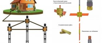
In this regard, the TT grounding system is used in summer cottages, hunting lodges, temporary structures at construction sites and other similar situations. The advantage of this design is that a simple earth-moving tool and electric welding are sufficient to make the grounding.
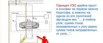
Due to the fact that the grounding resistance may be insufficient for reliable protection and disconnection of the circuit breaker, the PUE clause 1.7.59 indicates the mandatory installation of an RCD or a circuit breaker. The leakage current that appears when a person shorts to the body or touches live elements is sufficient to trigger this protection.
| Important! Grounding cannot be used as a neutral wire. This will lead to rapid corrosion of the circuit and its destruction. |
Official requirements for the protection device
According to the PUE, the operation of equipment grounded according to the TT system without an RCD is prohibited. There must be a mechanism that turns off the equipment when leakage current occurs when the insulation is damaged. The device is automatically triggered by the difference in the potential of the current flowing through the neutral cable and through the phase. Of course, it does not stop the leak, but it redirects it to the ground electrode.
The defining characteristic of a protective circuit is resistance. There are official requirements for it and for the TT system: R≤50B/Isr.uzo. If there are several RCD devices in the system at once, the differential current at the highest value is taken into account. When organizing grounding, potential equalization must be performed - the object's ground electrode, lightning protection, utility pipes (water and gas pipelines, heating, etc.), the frame of the protected building and everything metal in the ventilation are connected.
The finished TT system looks like a contour around the entire protected object, made of a plate or rod. And the connection with its own grounding conductor hidden in the ground is also visible.
Explanation of the TT circuit designation
The name and explanation of the TT grounding system indicates its main features:
- 1. T (English terra - earth). Indicates that the neutral of the power supply, as in TN systems, is connected to ground without circuit breakers or switches.
- 2. T (English terra - earth). Indicates that all elements of the enclosure are connected to the protective ground near the building.
From the name it is clear that the PE grounding is not connected to the supply transformer and is connected to its own grounding loop. It is the presence of this circuit that is the main difference between the CT grounding scheme and TN-type systems, in which the equipment housing and grounding terminals are connected to the neutral of the power source by PE or PEN wires.
How the TN-C circuit of a building works
The TN-C wiring system is based on the use of four wire strands for a three-phase circuit (3 phases and a common zero) and a two-wire circuit for a single-phase circuit. An option for connecting consumers of garages and summer houses via a four-wire overhead line is shown in the photograph.
The working zero of this circuit is connected directly to the ground loop of the supply transformer substation. No grounding is created in other places.
They are excluded by the design, which does not take into account emergency flows through additional circuits. Therefore, if the need arises for their installation, coordination with the energy supply organization is required for adjustment and recalculation of emergency modes that may arise in a new situation.
The previous material, presented in the first part of this topic, is devoted to the electrical safety of a summer house and a private home. He analyzes possible risks in detail and aims at the conclusion: it is necessary to radically change the situation, to adopt one of the methods of technical solution to the issue, working in automatic mode.
For a dacha and a private house, two connection schemes are better suited:
- TN-CS;
- TT.
Scheme of the TT grounding system
The operating principle of TT type protection is that the PE grounding wire is connected to an independent grounding circuit and is not connected to the power source. In this case, the structural elements of the building and communications are grounded and not connected to the power source.
Even if a transformer substation is installed next to the TT earthing circuit, the transformer neutral loop and the earthing loop are not connected.
| Important! It is prohibited to connect the PE and N wires in the TT system to each other directly or through other elements. This automatically turns the circuit into TN-CS type protection |
TT grounding system.
TT system
– a system in which the neutral of the power transformer is solidly grounded, and the exposed conductive parts of the electrical installation are grounded using a grounding device that is electrically independent of the solidly grounded neutral of the power transformer.
This system is designed for mobile buildings made of metal or with a metal frame, intended for street trade and consumer services (trade pavilions, kiosks, tents, summer cafes, booths, vans, etc.). The TT system is very popular
began to recruit in houses in the private sector.
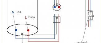
As can be seen from the figure, in the TT system phase L
and the zero working
N
conductors
are not electrically connected to the zero protective PE
. Here we make our own grounding loop, which is brought into the house and connected to the local internal switchboard.
From the shield there is a protective conductor PE
It is distributed to all sockets, and is also brought to the place where the lighting lamps are mounted in order to ground the metal bodies of the chandeliers. As you can see, the system is simple, but also has its drawbacks.
For example: a phase-to-ground short circuit has occurred.
A circuit breaker is unlikely to help here, since the resistance between the phase conductor and its own ground loop is very high. The current that will arise between them will be very small and the circuit breaker will not feel it, since such a current will not be a short circuit current.
If there is a residual current device such as an RCD
, responding to
leakage currents
, it will operate and turn off the power.
If there is a short circuit between the phase and the working zero, the circuit breaker will help out, but the RCD will not react. TT
system uses
combined protection
against electric current. And this turns out to be a little expensive - but life is more expensive.
When constructing a power supply circuit for a home, it is mandatory to use at least two residual current devices of the RCD type: one common at the input and one after the meter. The second RCD will duplicate the first one, in case the first one fails.
I will give an optimal scheme where the house is divided into groups of consumers, and for each group they install their own additional RCD. For example: bathroom - group No. 1, utility room - group No. 2, rooms - group No. 3, kitchen and hallway - group No. 4. Let's consider the internal configuration and installation of the main distribution board.
Let's look at the diagram.
From the 0.4 kV line, “phase” and “zero” enter the main distribution board of the house (MSB) and are connected to the input of the QF1
.
From the output of the machine QF1,
“phase” and “zero” enter the counter
SW1
, and from the output of the counter they are connected to the input
QF2
- a residual current device of the RCD type.
Next, from output QF2,
“phase” and “zero” go to the inputs of
QF3
and
QF4
RCD-type machines.
From the outputs of QF3
and
QF4
, each neutral conductor is connected to its
neutral block N1
or
N2
, and the phase conductors from these machines are distributed as follows:
1.
QF3
– phase is connected to the input of circuit breakers
SF1
and
SF2
, supplying power to consumer group No. 1;
2.
QF4
- phase is connected to the input of circuit breakers
SF4
and
SF5
, supplying power to consumer group No. 3.
3.
From output
QF2,
the phase conductor is connected by a jumper to the input of circuit breaker
SF3
, which supplies power to consumer group No. 2.
We have disassembled the power part of the circuit. When installing in the power section, the cross-section of the phase and neutral conductors is used to be at least 4 squares (in the figure, the conductors of the power section are highlighted with thick lines).
Now let’s look at how consumer groups are powered using group No. 1 as an example.
Let's say we distributed: machine SF1
supplies power to the sockets, and the
SF2
supplies the lighting. Let's start with the sockets.
A three-core wire with a cross-section of 2,5
square.
The first core is connected to the output
of the machine
SF1
, the second core is connected to
the zero block N1
, and the third core of the protective grounding
PE
is connected to
the ground block
, which has its own ground loop.
The lighting
is done in this way , but only the cross-section of the cores for lighting is
1.5
square.
And now, if there is a current leak in consumer group No. 1, then QF3
and will turn off power to that group. At the same time, voltage will be supplied to consumers No. 2 and No. 3.
From the junction box to each socket and to each chandelier there is a separate
three-wire wire. In this article, the installation is drawn in more detail.
Now let's look at group No. 2. To the input of the circuit breaker SF3
the phase conductor is supplied, which is taken from the output of the general machine
QF2 ,
and the zero conductor comes from
the neutral block N.
As a rule, a group of equipment that is not subject to enhanced electrical safety protection measures is powered in this way. And if there is a current leak, then QF2
, but in this case, it will turn off the general power supply of 220 Volts, that is, all consumers.
And a little more about protective equipment:
QF2
– protective shutdown device with leakage current of 300 mA;
QF3
,
QF4
- residual current devices with a leakage current of 30 mA;
SF1
,
SF4
- automatic switches for sockets - 16 Amperes;
SF2
,
SF5
- automatic switches for lighting - 10 Amperes;
SF3
- for example, for a powerful consumer - 25 Amperes.
Only with the advent of GOST 30339-95/GOST R 50669-94
and
PUE-7
it became possible to use the
TT
, but until that moment it was prohibited.
But even in the PUE there are restrictions on the use of the CT
:
1.7.59.
Power supply of electrical installations with voltage up to 1 kV from a source with a solidly grounded neutral and with grounding of exposed conductive parts using a ground electrode not connected to the neutral (TT system) is allowed only in cases where electrical safety conditions in the TN system cannot be ensured.
To protect against indirect contact in such electrical installations, the power must be automatically turned off with the mandatory use of an RCD. In this case, the following condition must be met: RaIa, where Ia is the tripping current of the protective device; Ra - the total resistance of the grounding conductor and the grounding conductor, when using an RCD to protect several electrical receivers - the grounding conductor of the most distant electrical receiver.
What are the requirements for the TT system?
PUE 1.7.59 indicates where the TT grounding system is used and the basic technical conditions for this design.
RCD installation
The TT system is more dangerous and does not provide the same reliable protection against electric shock as the TN-S circuit. Therefore, when installing this circuit, it is mandatory to install an RCD with a leakage current threshold of no more than 30 mA on all electrical wiring lines.
This requirement is justified by the fact that when a phase is blocked on a grounded equipment frame, the short circuit current can be so small that the circuit breaker will not trip. Therefore, the only protection in this case will be a Residual Current Device (RCD).
Lack of connection between N and PE conductors
The neutral wire N and the grounding PE must not be connected to each other. It is this separation that is a distinctive feature of the TT type system.
The PUE clause 1.7.59 states that it applies only if the requirements for other protection schemes cannot be met, and the connection of N and PE transforms the TT circuit into one of the TN type systems, the requirements for which in this situation are impossible to meet.
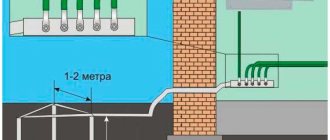
High-quality ground loop
One of the main elements of TT type protection is the ground loop. Unlike other schemes, it is located near a building with this protective system. The main parameter of the circuit is its resistance. For reliable operation, the circuit must be regularly inspected and tested with a grounding tester.
Installation of accounting and security devices in the panel
Now it’s time to install all the other elements on the DIN rail. The complete list of equipment required for the panel of a private house is as follows:
1) Steel electrical panel (protection rating IP54 or higher)
2) Box/casing for AV for 3 modules
3) Three-pole circuit breaker 25A
4) Three-phase electric energy meter 380V
5) distribution block for DIN rail
6) Selective RCD from 40A, leakage current 100mA or 300mA
The electricity meter must be three-phase, for 380V networks. Usually electronic, two-tariff is chosen. When choosing a manufacturer, the main guideline is the warranty period; the one with the longest warranty should be taken. Usually a simple one is taken, without unnecessary interfaces, for example, Mercury or Energomera.
The distribution block must have a sufficient number of terminals for the required conductor cross-sections. For the option with a VDT - residual current switch, with CT grounding, you will need:
1 terminal - 16mm.kv - for re-grounding circuit PV1 or PuV (PuGV)
2 terminals of 6mm.kv - for internal conductors used for switching
The fire protection RCD is selected selective - having a delay when triggered. The leakage current can be either 100mA or 300mA.
The choice of the response threshold of the Residual Current Device depends on many factors. Almost any electrical appliance has some leakage and this is normal. If there are many such devices, the total losses can be large.
Based on this, this value is selected. If the housing is small, it is enough to set 100mA. If this is a cottage, with a lot of technology and equipment, then definitely 300mA.
For internal connections in the panel, it is most convenient to use flexible wires PuGV (also called PV-3) 1x6mm.sq. and NShVI tips.