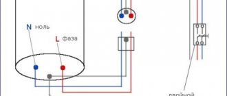
Installation of modular pin grounding is an excellent option for installing a grounding system (grounding loop) in a private home. In this case, the duration of installation work is significantly reduced. The functions of the grounding device are not inferior to the grounding loop made according to the triangle diagram using welding and other similar systems (linear, deep, electrolytic, etc.). In this publication we will show in detail how to install modular pin grounding with your own hands and what advantages it has over other systems.
System design
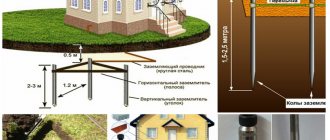
Why is this system interesting for owners of private houses and what is included in its kit? The design consists of steel pins 1.5 meters long with electrochemical copper coating and capable of being connected using couplings. To connect the horizontal and vertical parts of the structure, the kit includes brass clamps. Cone-shaped tips are designed to make it easier to bury the pins in the ground.
Modular-pin grounding
Assembly of the modular-pin grounding is carried out in the following order: a coupling is screwed onto the upper part of the pin, into which the impact head (drive attachment) is in turn mounted. A steel tip is installed on the lower part of the structure. It simplifies the process of driving ground pins into the ground. There are several types of tips, the scope of which depends on the hardness of the soil.
Modular-pin grounding kit
In addition, the kit comes with a special conductive paste, the purpose of which is to protect against corrosion and constantly maintain electrical resistance during operation. Electrically conductive paste is applied to all threaded connections of the structure. To prevent corrosion, you can use a special moisture-proof adhesive tape; it is resistant to acids, salts and gases, and does not allow moisture to pass through.
Modular grounding kit
In addition to vertical rods, the modular grounding kit includes couplings. They are made of brass and connect the rods to each other. Vertical and horizontal structures are connected with brass clamps.
The horizontal elements are a metal strip or copper wire. With their help, the grounding circuit is connected to the distribution panel. Two types of steel tips go to the vertical pins, depending on the density of the soil. They are removable and screw onto the rod as needed.
The main parts that are included in the modular grounding are supplemented by a landing platform and a special nozzle, through which the forces of the vibratory hammer are transmitted. Protection against corrosion is carried out using an anti-corrosion paste that has a liquid consistency and is capable of conducting electric current. Clamping brass connections are protected with special tape.
All places with threaded connections of structures are coated with electrically conductive graphite lubricant, which creates and maintains a constant electrical circuit with normal conductivity in all seasons. It adheres well to surfaces, and its properties practically do not change under the influence of temperature changes. The lubricant provides additional protection against corrosion and maintains a constant level of resistance during operation, filling all irregularities in joints and joints.
Sequential installation of elements
Installation of modular-pin grounding is easy and simple. Lubricate the thread of the first pin with conductive anti-corrosion paste and screw a cone-shaped tip onto it. At the other end, we install the coupling in the same way and screw the impact head into it, designed to protect the pin from the shock load of the hammer drill.
Installation of a ground electrode in the ground
We lower the assembled modular-pin grounding into a pre-prepared recess in the ground. You need to stick it as deep as possible into the ground with your own hands. Then connect the hammer drill to the network and insert its nozzle into the impact (guide) head. Thus, the pin will sink into the ground when exposed to the impact force of the hammer drill. To attach the next rod, you need to leave approximately 20 cm from the ground.
Below we provide the manufacturer's instructions for installing a grounding system using a hammer drill
Installation instructions for modular-pin grounding
After this, you should measure the grounding resistance. To do this, you need to remove the impact head and connect a special device, an ohmmeter, to the place where it was located.
Device for measuring ground resistance M-416
After the first pin has been buried into the ground for its entire length, the guide head for the hammer drill is removed and the next pin is screwed through the coupling. On the upper part we again mount the coupling and the guide head under the hammer drill, after which the process is repeated.
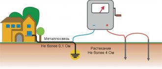
Note! The pins of the modular system can be placed not only in a line. They can be driven in at corner points using a triangle system, as well as along an arc. The total resistance to current flow created by the entire chain should not exceed 3-4 Ohms.
The number of pins driven in will depend on the total resistance to current flow of the entire system. The figure below shows a diagram of the change in resistance depending on the length of the electrodes (pins):
Graph of grounding conductor spreading resistance
After all the pins have been buried, they must be connected with a horizontal ground electrode using brass clamps. One of the vertical grounding conductors is connected through a conductor to the electrical panel.
Step-by-step instructions for performing the work
Work on the installation of modular pin grounding can be divided into several stages: preparatory, installation and final.
Preparatory stage
A grounding system kit is purchased, the necessary tools and instruments are prepared, and a location for installing the grounding system is selected.
Installation of the ground loop
Work on installing a modular-pin type grounding loop is carried out in a certain sequence.
In the place where installation is to be performed, the soil resistivity is measured. For this purpose, special instruments are used for comprehensive testing of grounding systems, produced by various manufacturers.
Once the soil resistivity has been determined, the required number of vertical electrodes can be determined using the formula: n = R*Ψ/Rн, where:
- n is the number of electrodes (rods);
- R is the spreading resistance of one vertical electrode;
- Rн - standard soil resistance;
- Ψ — seasonality coefficient.
When performing the calculation, you must first calculate and determine several indicators.
Spread resistance (R) of one vertical electrode. Determined by the formula: R = P/2*(1n(2L/d)+0.5ln(4T+L/4T–L)), where:
- P—soil resistivity, Ohm/m;
- L—electrode length;
- d—electrode diameter;
- T is the distance from the middle of the rod to the surface of the earth;
- ln is linear logarithm.
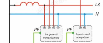
The standard soil resistance (Rн), in accordance with the “Rules for Electrical Installations” (PUE), must correspond to electrical installations with voltages up to 1 kV (at line voltages 660/380/220 V):
- in the immediate vicinity of the neutral - 15/30/60 Ohms, respectively;
- taking into account natural grounding and repeated grounding of outgoing lines - 2/4/8 Ohms, respectively.
The seasonality coefficient, in accordance with the PUE, is determined for different climatic zones as follows:
| Type of electrode | Climate zone | |||
| II | III | IV | ||
| Vertical | 1,8 – 2,0 | 1,5 – 1,8 | 1,4 – 1,6 | 1,2 – 1,4 |
| Horizontal | 4,5 – 7,0 | 3,5 – 4,5 | 2,0 – 2,5 | 1,5 |
Important! The calculation can be performed using special computer programs or using an online calculation calculator on the Internet.
When the number of vertical electrodes is determined, a decision is made on the shape of their location on the ground (line, triangle, polygon).
The shape of the grounding loop depends on the number of grounding conductors and the location of the structure from nearby buildings and utilities.
The soil is excavated to a depth of 0.5 - 0.7 meters in accordance with the selected configuration of the ground loop (a trench is dug). The first modular pin (vertical electrode) of the assembled structure is being installed.
Work on assembling the core structural element is carried out in the following sequence:
- A tip is screwed onto the lower end of the module and a special mastic is used.
- A landing pad is screwed onto the upper end of the module.
- The model is installed in the marked location of the trench. using an electric or pneumatic hammer, it is hammered to its entire length.
- If it is necessary to install another module in the design of a separate vertical electrode, the tool used is disconnected, the landing pad is turned out, and the coupling is screwed in its place, after which the next module is installed and immersed in the ground.
- When the first ground electrode is installed, an intermediate test is carried out - the resistance to current spreading of one vertical electrode is checked. The resulting value should indicate whether the preliminary calculations were made correctly. If the values do not match, you need to make adjustments to the circuit design - add or reduce the number of electrodes.
- Install the required number of vertical structural elements.
- Horizontal electrodes (grounding conductors) are placed in the trench, which are attached to the vertical grounding conductors using connecting clamps and a special paste.
- The trench is filled with soil with layer-by-layer compaction of the latter.
Final stage
At the final stage of the work, a control measurement of the mounted ground loop is carried out and the obtained values are checked for compliance with the requirements of the Electrical Installation Regulations.
Afterwards, the mounted structure is connected to the grounded elements (lightning protection system, electrical equipment and networks, utilities to be grounded).
Disadvantages and advantages
If we compare modular-pin grounding with a grounding loop made by welding, then pin grounding will have the following advantages:
- Easy and simple installation;
- Installation can be done independently with your own hands;
- No welding work is required, since the entire system is mounted using clamps and couplings;
- No heavy excavation work;
- The system is not susceptible to corrosion, as it consists of copper-plated elements and, accordingly, has a long service life;
- All elements of the modular-pin system are of high quality, as they are manufactured at an industrial enterprise;
- No additional preparatory work is required.
The only disadvantage of modular pin grounding is its high price. But, taking into account all the above advantages, this system is the most profitable option for ensuring the electrical safety of a private home.
Do-it-yourself modular-pin grounding: installation of a grounding loop in a private house
Modular-pin grounding is one of the options for a grounding loop in a private house. Compared to other types of grounding installations, this option does not require much time for installation work.
At the same time, the functionality of modular-pin grounding is at the proper level. We want to show you a method for self-assembling a pin ground loop, and what advantages such assembly has in priority.
The structure consists of steel pins, about 150cm long. They are treated with a copper coating approximately 250 microns thick and are fastened to each other with couplings. The vertical and horizontal parts of the structure are fastened with a brass clamp.
The necessary preparatory measures are carried out to carry out measurements of the spreading resistance of the main grounding conductors before installation. To do this, place the device in the immediate vicinity of the installation point, and prepare the measuring electrodes, which should be spaced at a distance of 25 and 50 meters.
The assembly of the modular-pin grounding structure is carried out as follows: a nozzle is attached to the upper part of the metal pin, which plays the role of a landing pad, after which it is connected to the coupling.
A vibrating hammer is applied to this attachment through a coupling to apply its force.
A tip is attached to the bottom of the pin, thanks to which the modular pin element fits better into the ground during installation. On the market, tips may differ from each other, there is a choice.
Taking into account the type of soil into which the modular-pin grounding element will be inserted, the optimal tip is selected.
The assembly also involves another component of the modular-pin design, such as a special paste designed to protect against damage by rust.
It also maintains electrical conductivity and electrical resistance at the proper level for the period of operation.
Apply the paste to all fastening points in which there is a thread and the fastening “goes by” twisting or screwing.
An alternative to paste, which can also protect against moisture, salts, gas emissions and acids in the soil, is the use of a special adhesive tape that does not allow moisture to pass through.
Next, we take the pin, treat the bottom at the attachment point with paste and attach the tip. We also apply electrically conductive paste to the upper part of the modular pin element and screw the coupling on.
We attach a landing pad to the coupling, to which the vibrating hammer will apply force. We place this structure in a hole in the ground, which we prepared in advance.
The pin is deepened by screwing in as deep as you can. And, after turning on the vibrating hammer, placing it against the rod site, they deepen it completely, leaving about 20 cm on the surface for connection.
Already in the immersed rod it is necessary to measure the value of grounding resistance. The landing nozzle is removed from it and an ohmmeter device is connected.
The grounding resistance must comply with PUE standards (electrical installation rules) and have clear indicators.
Regardless of weather conditions, the indicators should be equal to 8, 4, 2 Ohms, at voltages of 220, 380, 660 V, respectively, for a three-phase network. If the voltage source consists of one phase, then the voltage will be 127, 220 and 380V, respectively.
After the measurements have been made, disconnect the ohmmeter and connect the next rod, which is a continuation of the first, through the coupling, which serves as a connection.
The fastening, which holds the rod in the upward position when immersed, remains on the surface of the earth in a fixed mechanism.
Next, the fastening is detached, a coupling is put on, which connects the attachment for the vibratory hammer, and by connecting the latter, the pin is also deepened to the end.
The situation is repeating itself. It is recommended to take measurements with an ohmmeter with each pin after it is immersed in the ground.
And the number of pins themselves, as well as their installation, are carried out until the required resistance is achieved and will depend on the total resistance to the current spreading of the entire system.
At the final stage, we connect the ground electrode located in a horizontal position and the vertical rod. Using a brass clamp, we fasten it to the part of the conductor (pin) that remains above the ground.
Between the vertical rod and the horizontal cable there is a specially designed protective plate. It is able to prevent corrosion when joining metals even of different compositions.
Already in the assembled structure, the fastening zones are once again wrapped with additional protective film tape, again for protection against oxidation and erosion.
Of course, there are no ideal systems. The modular pin grounding design also has its pros and cons.
Among the advantages, I would like to highlight the main and important advantage of the system - it is a highly reliable protective barrier for the inhabitants of the house from electric shock and fire in the house due to surges in electrical impulses in the wiring.
Additionally, I would like to emphasize that the installation and installation of the structure is quite easy to implement. Geographically – grounding does not occupy a large area.
When working with the installation, one or two people are enough and there is no need to involve more participants.
When using couplings and their reliable fastening, it is possible to do without the use of a welding machine, and with the use of a vibrating hammer, it is easier to work with soil, with any type of soil.
If you conscientiously follow the treatment measures with additional pastes, films, etc., then you can confidently say that modular-pin grounding is resistant to corrosion and durable in operation (at least up to 30 years).
The grounding design elements are initially manufactured at the factory and are components of a pre-calculated circuit. It is important to choose the right parameters and then there is practically no preparatory work left.
For example, if there was a need for some kind of individual component created for a specific requirement.
The only disadvantage of modular pin grounding is its cost. This is not to say that modular pin grounding is a cheap device. But during operation it completely justifies the costs.
You must remember that the installation and connection of this type of grounding installation must be accompanied by permitting documentation.
These include: measurement protocol, hidden work reports, installation passport with diagram. The owner must keep all this for himself.
That's all we wanted to write about modular pin grounding in this article. Thank you for your attention. We hope that we have clarified the path for you to install modular-pin grounding yourself.
Comparison of modular and conventional grounding
A comparison of conventional grounding and a modular system shows many obvious advantages of modular pin grounding.
| Conventional grounding | Modular pin grounding |
| Welding required | Welding work is not performed |
| A labor-intensive and lengthy process that requires large volumes of excavation work | Even one person without experience can handle the installation |
| A truck is required for transportation | The entire system can be carried by one person |
| Material cutting required | Installation occurs using couplings and bolted connections, no cutting required |
| Significant area required | Required installation area - 1 sq. m |
Installation instructions
Installation of modular grounding begins with the preparation of the first pin. We treat the starting tip with conductive lubricant and place it on the pin on one side. We also treat the coupling with lubricant and put it on the other side of the pin. We screw the guide head for the hammer into the coupling from the free side.
We drive the pin into the ground using a jackhammer to the depth required for further work.
Remove the head from the pin without a coupling. We treat the remaining coupling with lubricant again. We connect the next pin to the coupling. We take a new coupling and also treat it with lubricant. Screw the head back into the new coupling. We connect everything with a pin already installed in the ground.
We drive the pin into the ground again. We repeat the operations to obtain the required penetration depth of the grounding electrodes.
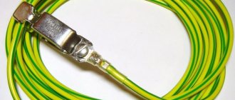
When it comes to the last pin, you need to leave part of it on the surface of the earth for subsequent connection to the grounding conductor. We place a clamp on the electrode. We connect the grounding conductor to it. We wrap the clamp with waterproofing tape.
Installation stages
Final installation diagram: 1 - down conductor (round conductor), 2 - round conductor in PVC sheath, 3 and 4 - conductor holders with cover plate and flange, 5 - universal disconnect terminal, 8 - connecting clamp, 9 - grounding rod, 10 - tip.
* Click on the diagram to enlarge.
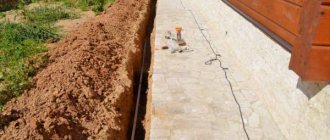
1. Initially, it is necessary to prepare the place for installing the rods in the ground. To do this, dig in the soil approximately 70-80 cm. In this case, it is necessary to maintain a minimum distance from the foundation of about 1 meter.
2. Screw the tip onto the end of the ground electrode (or press it with a little manual effort).
3. Screw the coupling onto the opposite side
4. The impact tip is screwed onto the coupling. In German kits, the impact head is placed on a part of the rod with a decrease in diameter.
5. The structure is hammered in, leaving the free end protruding from the ground as far as it will allow you to comfortably continue installing the next rod. This can be done either manually or using a vibrating hammer or hammer drill.
6. I unscrew the impact head and screw the next rod in its place. In this case, the joint “rod-coupling-rod” is lubricated with conductive paste. In foreign analogues, since a transition coupling is not used, the rods are joined into a joint without the use of lubricant or paste.
7. Repeat installation operations 3-4-5-6
8. The last rod should protrude from the ground at a distance of approximately 20 cm so that after filling the installation hole it is 40 - 50 cm from the surface. A connecting clamp is mounted on its free end and the structure is connected to a round conductor or strip.
9. The joint is sealed with anti-corrosion tape, as shown in the figure.