December 8, 2020
Dreaming of a carefree life in a cozy private home, many completely forget about banal security measures. This applies not only to security systems, but also to more important structures such as lightning rods and grounding.
The main problem is that these things seem ordinary, or, on the contrary, completely unnecessary. Most new owners of private homes pay absolutely no attention to this issue, faced with regular breakdowns of household appliances and electronics.
Organizing proper grounding in the electrical network of a private home is not a need, it is a necessity. This system allows you to secure the process of using household electrical appliances, and at the same time protect you from colossal expenses in the event of their breakdown due to short circuits and power surges.
Although the contours themselves are quite understandable structures, there are many nuances, including design requirements for each type of residential building. That is why we will tell you not only how to correctly make a grounding loop, but also how to perform calculations, prepare financially for the procedure, and select the necessary tool.
Features and principles of grounding
The purpose and objectives of the ground loop are quite capable of characterizing the structure itself.
Grounding is a connection of all elements and “participants” of the electrical network with a grounding loop, which allows, in the event of leakage currents, to safely discharge them into the ground.
Damage to insulation, short circuits, and almost any other troubles that may arise during the operation of devices can be neutralized due to a properly installed ground loop.
In simple words, if the electrical wiring is damaged, the electric current will not harm you or your loved ones.
The main danger of short circuits is that they not only disable electrical appliances, all the accumulated potential will be transferred to the conductor at the first opportunity, which, in the event of touching bare wires, is a person. Grounding is designed to take on the task of safely draining electricity into the ground in the event of a breakdown in the electrical network.
grounding installation
Compared to the process of building a house itself, the grounding device looks, at first glance, quite simple. However, if you delve into the reasons for its necessity, then this procedure will turn into a very responsible process that requires careful thought. Why?
Answer your question: why are all electrical wires without exception necessarily insulated? In order to prevent the conductor from coming into contact with any surrounding substance that has resistance, like the material from which the conductor itself is made. This is important for two reasons:
- energy leaks are not allowed;
- We are talking about a short circuit situation where electrons from a wire with a high potential flow without any significant resistance to a wire with a low potential. And this is an extremely dangerous situation.
But what does grounding have to do with it? The thing is that a “short” breakout does not always form immediately. Sometimes the leak described above forms gradually, literally, in parts:
- first, the core insulation is imperceptibly damaged;
- then, for example, the environment around becomes damp, becoming conductive;
- finally, thanks to a negative coincidence, such an “impromptu” chain involves, for example, a metal bathtub...
In the latter case, electricians say that the object (the bathtub) is under a mass. This means that you should never touch it with unprotected hands, otherwise you will close this circuit with your body, and a current of deadly force will pass through you. So, it is precisely in order to avoid such a development of events that there are rules for installing grounding.
The ground electrode is a conductor with low resistivity, which at one end is attached either to the reinforcement of a capital structure, or to massive household or industrial metal objects that may be under the mass. The other end of the conductor is connected to the earth's massif.
It is known that the electric current supplied through the power transmission line wires travels back (to the power plant bus) through the ground. This was done because it would be very expensive to provide a separate wire for the zero phase. That is, the ground is, in fact, the same second wire with a low current potential. Only the same bath (or machine) can be isolated from the earth's massif. If we ground it - that is, we connect it to the ground using, for example, a metal corner, then if a “short” electrical circuit is accidentally formed, as soon as the mass “reaches” the grounded object, a short circuit will occur, and the machine, through which produces power to the circuit will automatically break the circuit. This will protect electrical equipment from significant damage, and most importantly, it will save the life and health of people who may accidentally touch an ungrounded object.
Is grounding necessary at all in private houses?
As mentioned above, a ground loop is an excellent safety measure for homeowners. But is grounding really necessary in private homes? Now we will explain everything both from a safety point of view and based on the requirements of legislative acts.
Grounding is not an ideal means of protection against electric shock, since not all designs are capable of discharging large amounts of energy almost instantly. Despite this, even a decrease in the accumulated potential can significantly reduce the strength of electric shock. In critical situations, this allows you to avoid a lot of troubles, including death.
In addition to practical necessity, it is worth taking into account the requirements of legislative norms, which are quite understandable and transparent.
According to GOST, SNiP and PUE, all residential premises are required to be equipped with similar protection systems. The lower threshold in the requirements for installation of such circuits is an alternating current power supply of 100 Volts and more than 40 W.
Thus, 90% of all household networks in our country should be equipped with similar units to ensure the protection of homeowners from injuries.
Also, a grounding loop is one of the effective fire safety measures. Small fires, or large fires, bring much more losses than the cost of installing grounding, so you should definitely equip your own house with a similar design.
An interesting fact is that the lack of grounding in a private home can negatively affect the quality of mobile communications. An ungrounded electrical network creates a lot of interference for almost any electronics, so many people ask this question only after encountering interference with the equipment.
It is also worth considering that although the grounding system and lightning rod have similar principles of operation, the contours of these systems should in no case be ringed. In the case of a lightning strike, such a move can lead to even more negative consequences. A powerful electrical discharge will simply destroy all electronics, and as a result can create a fire inside or outside the house.
Do-it-yourself grounding
As can be understood from the above, installing grounding in a private house is a fairly simple operation that anyone can handle if they thoroughly prepare for it and calculate everything correctly.
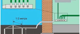
First of all, you need to choose a place. This should be a flat area, sufficiently far from the house - it is advisable that people and pets do not walk along the grounded area. In addition, installation of the system closer than 1 m from buildings is not allowed. In this case, it is advisable to fence off the location of the ground loop, which will allow you to quickly find it in the future if any problems occur. The location of the electrodes must be marked.
Grounding installation occurs as follows:
- Marking is carried out (the most effective is the scheme in which the electrodes are arranged in the form of an isosceles triangle).
- A trench is dug along the entire marking (including for the bus that goes to the electrical panel).
- Electrodes are installed to a depth of about 2-5 meters, to which the connecting busbar is welded.
- The bus from the circuit is laid underground to the distribution panel, where it is secured with a bolted connection. If the wiring diagram suggests, the bus is connected to a splitter bus.
When everything is ready, the grounding system must be tested to ensure its effectiveness. To do this, the electrical resistance of the entire system is measured, which cannot be higher than the values specified in regulatory documents.
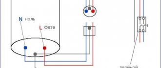
There is an easy way to check the grounding system. You need to take an ordinary 100 W lamp and connect it with one pole to the phase and the other to ground. If the lamp burns evenly and brightly, the circuit is assembled efficiently. If the glow is dim, you need to check the quality of the contacts. The absence of light indicates poor quality installation.
Rules, regulations and basic requirements of the PUE
It's time to get acquainted with the basic requirements for grounding systems in private homes. The main parameter is the loop resistance, which determines the reliability and efficiency of the system.
The lower the resistance of grounding devices, the higher their reliability.
Ohm's law states that the current in a section of a circuit is directly proportional to the voltage and inversely proportional to the electrical resistance of a given section of the circuit.
Thus, the lower the resistance, the greater the likelihood of the ground loop tripping.
For most residential buildings with 380V and 220V electrical networks, the resistance should not exceed 30 ohms. Moreover, if the house is equipped with a gas boiler, then the resistance should not exceed 10 ohms.
The Electrical Installation Rules (PUE) determine that every residential property within the city must be equipped with special measures to protect against dangerous voltages. We are talking specifically about metal grounding loops, which guarantee protection of residents from electric shock.
Chapter 1.7, part 1, paragraph 1.7.72 of the PES states that the dimensions of metal elements are selected taking into account the final resistance indicator (mentioned above), and the parameters of each structural element may differ in their characteristics.
The minimum size requirements are still strictly defined:
- Connecting strip - no less than 12x4 mm (section no less than 48 sq. mm).
- Pins (metal corner) - metal thickness is at least 4 mm.
- Round reinforcing pins - cross-sectional area of at least 10 sq. mm.
- Metal pipes - wall thickness of at least 3.5 mm.
At first glance, all this information may seem too complicated and even unnecessary. Nevertheless, information about the characteristics of the grounding loop and the equipment used on the site will protect residents and animals by preventing network overload.
Requirements for the grounding system
For grounding to function fully, all its elements must meet the relevant requirements, and installation must be carried out according to a strict scheme. If these conditions are not met, grounding in a private house will not effectively protect the house from voltage surges.
Conditions for installing the ground loop:
- The external part of the system should not be closer than 1 m from the house and no further than 10 m. A distance of 2-4 m is considered optimal.
- The electrodes are placed at a depth of approximately 2-3 m. Part of one of the pins is brought to the surface to connect an external bus.
- The cross-section of the external connecting strip, with the help of which the grounding is connected to the switchboard, cannot be less than 16 mm2.
- The connection of underground electrodes should be carried out exclusively by welding. In the distribution board, bolts can be used for fastening.
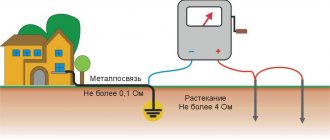
- Resistance cannot be higher than 4 ohms for 380 W and 8 ohms for 220 W.
When choosing a grounding kit, you need to navigate the location and take into account the specific location of the house. For example, if the structure is located in a cold region, the electrodes must be deepened below the soil freezing level, otherwise the structure will gradually be squeezed out to the surface.
If you want to arrange grounding in a private home according to all the rules, we recommend purchasing one of the ready-made grounding kits, each of which is made of durable materials with high resistance. Such kits are selected taking into account operating conditions, which is a guarantee of their effectiveness.
Technical requirements for ground loop resistance
Now that we’ve sorted out the theory, we can move on to analyzing the technical component of this issue. For private houses, it is first worth studying Chapter 1.7 of the PEU, which regulates the installation of grounding loops in networks up to 1000V. This category includes all residential private houses, so when selecting components you need to be guided by this standard.
According to this document, resistance can reach several indicators:
- Up to 0.5 Ohm for electrical installations with voltages over 1000 Volts with high ground fault currents (more than 500 A).
- Up to 4 Ohms for installations up to 1000 Volts (the category of private houses, dachas, cottages we need).
- No more than 10 Ohms for electrical installations with voltages over 1000 V and small ground fault currents.
- No more than 10 Ohms, if the total total power of electrical installations does not exceed 100 kVA.
This is what the regulatory documentation looks like, allowing you to select the correct parameters of grounding loops when selecting materials and components for their installation. Now let's move on to studying the structures themselves, which make it possible to effectively drain large fault currents into the ground.
Types of circuits and grounding schemes
The rate at which current is drained into the ground directly depends on the efficiency of the system itself. Grounding connections are structurally very similar to lightning rods, since they perform the same task, but this also applies to the technical component.
The more electrodes that simultaneously remove the electrical charge, the less time it will take.
There are three types of grounding:
- Modular-pin is the simplest type of circuit, which is an analogue of a lightning rod in the form of a single electrode going deep into the earth. Due to low efficiency and narrow application due to differences in soil hardness, it is practically not used. Despite this, this option is much more effective than the complete absence of grounding in the house or country house.
- Linear is a compromise solution, since the efficiency of an open loop is much lower than that of a closed loop. However, if you do not have the required amount of space, a linear outline can greatly save the situation. Technically, it represents a chain of electrodes located on the same line or in a circle at a distance of 1-1.5 units relative to the length of the electrode. For greater efficiency, you will have to increase the tapping points.
- A closed circuit (triangle) is the most effective method of protection against short circuits and voltage surges in the network. The closed triangle allows large leakage current to be quickly and efficiently removed without the need to deepen the electrodes to great depths. The rigid connection of the pins can significantly improve the quality and efficiency of the circuit, while the circuit can significantly reduce installation costs.
Let's look at the last option, since it is recommended to use this option in private residential buildings, dachas or cottages.
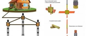
The design is quite simple, you will need:
- Three pointed rods of equal length - 2-3 meters.
- Three connecting strips of equal length - 1.2-1.5 meters.
These components are connected to form an equiangular triangle, with one pin extending from each vertex. For connection, it is best to use electric welding, which will turn all components into a reliable monolithic ground loop.
We considered the necessary parameters of each element at the beginning of this article, so now it is worth mentioning the depth and dimensions of the triangle.
The minimum depth is 0.5 meters, but if possible it is worth increasing this parameter. The length of the pins is within 2-3 meters, while the distance between them in the finished structure varies from 1.2 m to 1.5 meters, at your discretion.
It is worth digging such a circuit in any convenient place near a residential building to the depth indicated above. If you are strictly limited in area, you should pay attention to other grounding schemes. Remember - ineffective grounding is better than no grounding at all.
Types of ground loops
Grounding schemes in a private house
There are several types of structures used for grounding.
Traditional grounding systems
A system of this type consists of a minimum number of elements: two vertical electrodes made of metal reinforcement and one horizontal in the form of a strip, which connects the two previous ones. The sections and dimensions of the elements must comply with the standards. It is recommended to install grounding on the northern shaded side of the site, in a damp place. However, due to the fact that the contour is often made of steel and cannot be coated with paint, it quickly corrodes. Also, the resistance of such a device is affected by the temperature and moisture level of the soil, since the circuit is placed in the upper layers.
Deep grounding systems
Deep grounding system
This system is manufactured using a modular-pin method. Compared to the previous version, it differs:
- long service life;
- simple calculations;
- non-exposure to environmental influences;
- no need for maintenance;
- ease of installation.
Resistance measurements of mounted equipment should be carried out by specialists.
The external grounding loop consists of vertical electrodes and horizontal grounding elements. It is made of four strips 40-50 mm thick and installed at a distance of at least 1 m from the building. The horizontal strip should be located at a depth of 50 to 70 cm from the surface.
DIY grounding installation in a private house
We proceed directly to the process of installing the grounding loop on the site.
To make a ground loop with your own hands you will need:
- Angle grinder for cutting and cleaning seams.
- Wrenches M12 and M14.
- Bayonet shovel for digging a trench to the installation site of the circuit.
- A sledgehammer for deepening current-carrying pins.
- Welding machine for assembling the structure.
In addition, depending on the soil, you may need a crowbar or a hammer drill. They can come in handy when you come across a rock while digging trenches.
Now let's devote a few more words to a set of materials for making a ground loop.
List of required materials:
- Metal corner 50x50 mm with a metal thickness of 5 mm - 3 pieces of 3 meters each.
- Steel strip 40 mm thick 4 mm - 12 meters (for one grounding point).
- Bolts M12 or M14 with washers and nuts - 2 pcs.
- The copper conductor for diverting the circuit from the building is a copper cable with a cross-section of 6-10 sq. mm.
Do not use corrugated reinforcement or round steel with a diameter of less than 10 mm as grounding conductors. The minimum requirements for a grounding conductor is a corner 40x40x5 mm or a steel circle with a diameter of 14 mm.
All of the above will allow you to assemble a high-quality and reliable grounding circuit that will protect your loved ones and the entire house from electrical troubles.
Before deepening the pins, it is worth sharpening one of their edges; the best option would be an angle of at least 30 degrees. This will make it much easier to bury the corner into the ground.
We proceed directly to the excavation work.
To simplify driving in the pins, you can create three vertical holes using a drill, and only then drive the ground electrodes into the ground. Do not forget that the entire structure must be buried 0.5 meters into the ground, accordingly, all parameters must be calculated starting from this depth, and not the surface of the earth.
After driving the pins, you can start welding all the components into a monolithic structure. Due to the equal length of the steel strip segments, you will end up with an isosceles triangle in any case. Don’t forget to position it so that one of the vertices “points” to the house itself; it is from this that you need to take the remaining strip for connecting with the house wiring.
We will also give you some tips - it is best to buy materials with a reserve, based on the maximum length indicated above. This will allow you to reinsure yourself, while the pins may become deformed during the driving process, and accordingly reduce their length. It is also worth doing with the metal strip, since the dimensions may change when welding or cutting.
Main functional units of the grounding system
A complete grounding system consists of:
- Ground loop.
- Strip metal.
- Copper grounding conductors.
Let's take a closer look at each of the elements and their functional purpose.
Ground loop
A ground loop is a group of interconnected conductors or electrodes (in most cases, stainless or ordinary steel) that are located vertically in the ground and located near the protected object.
Depending on the characteristics of the protected object, 50x50x5 mm corners (grounding for a gas boiler in a private house) or round steel (ᴓ16–18) are used to construct a grounding loop, which are driven into the ground to a depth of 3 m. After which these electrodes are welded together with using a strip (4x40 mm) and bring the above strip to the connection point of the general grounding system of the house.
Ground loop diagram for a private house or cottage
Today there are 2 main types of ground loop:
- Closed in the form of an equilateral triangle.
- Linear.
Since the linear grounding loop has a significant drawback - if the connector between the electrodes is severely corroded, part of the loop will simply not be able to remove potential from the electrical equipment and thus the main functional purpose of the loop will not be fulfilled. For this reason, the installation of this circuit will not be discussed in this article.
Structurally, the ground loop is made with your own hands in the form of an equilateral triangle with a long side of 3 m. The optimal distance from the ground loop to the foundation is 1 m.
As mentioned earlier, the vertices of this triangle are either a 50x50x5 corner or round reinforcement with a cross-section of 16–18 mm (hereinafter referred to as “electrodes”). Before driving the electrodes into the ground using a sledgehammer or any other tool, you must first sharpen them, since otherwise you will not be able to drive it to a depth of 3 m.
After driving the electrodes to the required depth, along the contour of the resulting triangle, it is necessary to remove a layer of soil of 30–50 cm. This is necessary in order to simplify the welding of the electrodes to each other in the future. Welding of grounding conductors to each other is carried out using a regular 40x4 mm strip.
After welding the electrodes, a 40x4 strip with a welded M12 or M14 bolt with nuts and washers is placed on the foundation of the building in one or several places, to which a grounding conductor (in most cases yellow-green) is then connected, which is one core of the VVGng (PVSng) input cable ) 3x6, VVGng (PVSng) 3x10.
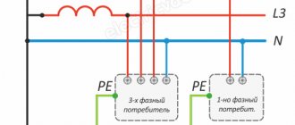
If the house has a 3-phase power supply system, then the input cable can be (PVSng) 5x6, VVGng (PVSng) 5x10, in which 3 lived - these are phases “A”, “B”, “C”, the zero wire is blue colored “N” and the grounding conductor “G” yellow-green.
Tricks when installing a ground loop
When putting an object into operation, very often cases arise when, when checking the resulting ground loop by a specialized electrical laboratory, the resistance value is higher than 4 Ohms. This may be caused by high soil resistance or failure to comply with the designed grounding requirements.
In this case, you can dilute 2-3 packs of salt in a bucket of water and pour the resulting solution into the places where the electrodes are located. Thanks to this simple manipulation, you can reduce the value of the ground loop resistance to 1–3 ohms.
After familiarizing yourself with the theory, let's consider a practical answer to the question: “how to make grounding in a private house with your own hands”?
Ready-made kits or manual assembly?
Many owners who decide to make a grounding loop with their own hands may have a reasonable question: isn’t it easier to use ready-made grounding kits?
No, it’s not simpler; more precisely, it’s not always simpler, and sometimes even more expensive. Ready-made kits are a compromise solution, since with time savings you get a higher cost, but the quality of the materials is not always the same.
Most stores sell modular or linear circuits, which are relatively cheaper, but do not always provide the proper quality of electrical conductivity.
By independently selecting and connecting all the components, you will be 100% confident in the quality of the grounding circuit, and therefore in the safety of the entire house. But you shouldn’t give up ready-made kits - they are perfect for arranging a small dacha or cottage, garages and utility rooms equipped with an electrical network.
Before you bury the entire structure, it is necessary to paint the visible part of the contour for reliable protection against corrosion. It is best to clean the entire plane of the elements, since poor preparation before painting will lead to accelerated corrosion of the metal.
After completing all installation work, you need to bury the trenches. Another tip is that before digging, you can fill the fresh soil with a saline solution, which increases the conductivity of the circuit. To prepare it, follow the proportion of 2-3 kg of salt per 10 liters of water. Afterwards, you need to carefully compact the soil for better contact with the contour; low density has a negative effect on soil resistance indicators.
Nuances and pitfalls in using a ground loop
No matter how well you calculate the quantity and quality of materials, there are nuances that do not depend on them, but every homeowner should know about this.
First of all, we are talking about the resistance of the soil itself, because it varies depending on its characteristics. For example, the resistance of peat is only 20 Ohms per 1 cubic meter, but the values of sand can reach 1000 Ohms per 1 cubic meter. Chernozem and clay practically do not differ in their characteristics; their resistance per 1 cubic meter is 50 Ohms and 60 Ohms, respectively.
Also, the level of resistance is influenced by the depth of the water horizon; the closer it is to the surface, the lower the soil resistance. Be sure to take into account the exact type of soil in your region and determine at least approximate resistance values, so you will be confident in the quality of the grounding.
So, we have examined all the important features and requirements for grounding loops for private houses. If you did not know how to properly make a grounding loop, all the diagrams, features and specifics of the installation process of such systems are discussed here.
Installation of modular grounding
The pin design of modular grounding ensures maximum convenience and manufacturability of installation:
- any ground loop configuration
- all parts are mated without welding
Vertical grounding electrodes of the required depth are mounted from 1.5-meter pins, buried in the ground one after another using a conventional electric jackhammer (with an impact energy of 20-25 J). The pins are connected to each other using simple threaded couplings (without welding). A bolt clamp is used to connect the grounding conductor.
The grounding configuration (single- or multi-electrode) is selected depending on the available area, type of soil and type of object (residential or industrial).
Deep installation in the form of one electrode to a depth of 15 - 30 meters is the most technologically advanced and allows for very effective grounding:
- quality (grounding resistance) does not depend on weather and time of year
- Possibility of installation inside the perimeter of buildings (in basements)
- minimum ground loop area
- minimum excavation work
How to check the ground loop after installation?
All the actions described below must be carried out before backfilling the trenches, so do not rush; a repeated check will allow you to be even more confident in the reliability of the structure.
First of all, carry out a visual inspection:
- Check the joints of the elements for the quality of welding, as well as the presence of cracks.
- Examine for any signs of damage to the connecting wire and metal strip.
- Inspect the quality of painting of the elements and, if necessary, correct damaged areas.
Using the same principle, it is necessary to carry out annual monitoring of the condition of the grounding loop of a private house. Thanks to this, it will work for many years, without the need to replace elements.
In addition, it is worth paying attention to periodic checks of the physical parameters of the circuit, such as resistance. The PEU states that the total resistance of all repeated groundings at any time of the year should not exceed 10 and 20 Ohms for networks with voltages of 380 V and 220 V, respectively. At the same voltages, the resistance of each individual grounding element should not exceed 30 Ohms and 60 Ohms for networks of 380 V and 220 V, respectively.
Be sure to remember - in addition to compliance with technical parameters, the grounding circuit must meet all the requirements of GOST and PEU standards regulating this issue. Only complete compliance with them will allow you to be 100% confident in the operation of grounding for a private home.
Ground loop resistance measurements
After completing all installation work, our specialists must measure the actual spreading resistance of the circuit, which, according to current regulatory documents, should not exceed 30 Ohms for a single-phase network and 4 Ohms for a three-phase network.
Based on the results of installation and testing, a Grounding Device Certificate is drawn up, which is handed over to the Customer along with a set of accounting documents.
Read more about grounding resistance tests >>>.
The final stage is introducing grounding into the house
Although we have already sorted out all the street work on organizing the grounding loop, we still need to think about connecting the electrical wiring and the grounding loop.
For connection you need to use the same bus as for connecting conductors. It is best to try to “reach” the metal bus directly to the electrical panel, but if this fails, you should do it at least from the outside of the house, and then connect it using a copper wire with a cross-section of 6-10 mm2.
If it seems to you that everything is so simple, do not forget that there are several connection schemes - TN-CS and TN-S.
The TN-S circuit is the most modern and reliable type of electrical wiring. This scheme is compatible with transformers with a solidly grounded neutral, while the N and PE conductors are separated along the entire line from the substation to the consumer. This option involves the use of a five-core cable, which ensures maximum efficiency and safety.
The TN-CS circuit is an excellent option for organizing grounding on a temporary basis. Based on this diagram, the neutral conductor N intersects the conductor PE, and in this case several grounding points are necessary. A common wire PEN is drawn from the substation, which is divided into PE and N at the supply to the residential building. Most often, such schemes are used in areas of new buildings, or in the absence of a modern electrical network in the region. In the latter case, it is necessary to wait for the installation of a full five-wire system by electrical services.
The main disadvantage of the second option is the need to lay the wiring with a three-core cable, which will still have to be replaced with a more reliable five-core cable. Also, if it is necessary to connect a three-phase 380V network, you must use the same five-core cable. Based on all this, it turns out that the cost of installing wiring according to this scheme is economically unprofitable.
If you initially take care of installing the correct type of wiring, implementing grounding will not be a problem for you. In addition, the use of a five-wire line will allow you to save significantly, since you will not have to re-install electrical networks in your own home.
Tags:
- electrical installation
Rate the material: