3.1. Principles of constructing a three-phase system.
Three sinusoidal EMFs of the same frequency and amplitude, shifted in phase by 1200, form a 3-phase symmetrical system.
Advantages of a 3-phase system:
1. The 3-phase system allows you to obtain a rotating magnetic field using 3 fixed coils, which greatly simplifies electric motors.
2. A 3-phase machine (generator, motor, transformer) is much simpler than 3 single-phase ones.
3. Using a 3-phase system allows you to get 2 different voltages (220/127, etc.).
4. When rectifying 3-phase voltage, ripple is minimal.
A 3-phase EMF can be obtained by rotating 3 frames mutually located at an angle of 1200 and located in a uniform magnetic field or by rotating a magnetic field with stationary frames (windings). EMF in windings:
EA=Emsin
wt
;
EB=Emsin(
w
t -1200);
EC=Emsin(
w
t-2400).
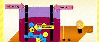
In reality, 3 windings are placed on the stator, and the rotor, which creates a magnetic field, rotates. Thus, to obtain a three-phase EMF, a synchronous generator is used, connected by wires to a 3-phase consumer (motor, transformer, lamp) forming a 3-phase circuit. In a 3-phase circuit, a 3-phase current system flows, i.e. sinusoidal currents with three different phases. The section of the circuit through which one of the currents flows is called a phase.
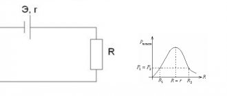
There are several possible ways to connect a generator to a load, and the simplest connection method is a 3-phase unconnected circuit (Fig. 3.3), in which each generator winding powers its own load. This circuit requires 6 wires and is practically not used.
Start of windings - A, B and C
, and the ends are
X, Y and Z
With a symmetrical load voltage UA, UB, UC
and currents
IA, IB, JC
are the same.
Three-phase electrical circuits
Basic concepts. Elements of three-phase circuits.
Three-phase circuits are a special case of multiphase AC systems. Multiphase systems are a set of electrical circuits in which sinusoidal EMFs of the same frequency operate, differing in phase from one another and induced in the same energy source. Each of the single-phase circuits included in a multiphase system is usually called a phase (in electrical engineering, the term “phase” has two meanings: a concept characterizing the stage of a periodic process, and the name of single-phase circuits forming a multiphase system). Depending on the number of phases, circuits are called two-phase, three-phase, six-phase, etc.
Three-phase circuits are most widespread in modern power engineering. This is explained by a number of their advantages, both over other multiphase circuits and over single-phase AC circuits. Among these advantages are:
cost-effectiveness of energy production and transmission compared to single-phase circuits;
the possibility of relatively simple production of the rotating magnetic field necessary for a three-phase asynchronous motor - one of the most common AC motors; the possibility of obtaining two operating voltages, phase and linear, in one installation.
A three-phase circuit consists of three main parts or elements: a three-phase generator, in which mechanical energy is converted into electrical energy with a three-phase EMF system, a transmission line with all the necessary equipment, receivers (consumers), which can be either three-phase (for example, electric motors) or and single-phase (for example, incandescent lamps).
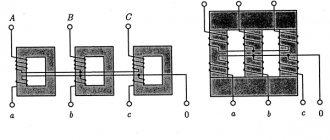
A three-phase generator is a synchronous machine of two types: a turbogenerator or a hydrogenerator (a schematic representation of a three-phase generator model is given in Fig. 2.11). The generator stator contains a winding consisting of three parts or, as they are commonly called, phases. The phase windings are located on the stator in such a way that their magnetic axes are shifted in space relative to each other by an angle of radians. The beginnings of the windings are designated by the letters A, B, C, and the ends by X, Y, Z.
The EMF in the stationary turns of the stator winding is induced as a result of the intersection of these turns by a magnetic field excited by the winding current of the rotating rotor (in Fig. 2.11, the rotor with winding is conventionally depicted in the form of a permanent magnet with poles N and S). The excitation winding located on the rotor is powered by a constant voltage source (exciter). When the rotor rotates at a uniform speed, periodically varying sinusoidal EMFs of the same frequency are induced in the windings of the stator phases, but differ from each other in phase due to their spatial displacement.
In the diagrams, the winding (or phase) of the power source is depicted as shown in Fig. 2.12. The conditional positive direction of the EMF in each phase is taken to be the direction from end to beginning. Typically, the EMFs induced in coils have the same amplitudes and are shifted in phase relative to each other by the same angle. Such an EMF system is called symmetrical.
2.4.2. Methods for depicting a symmetrical three-phase EMF system
A symmetrical three-phase EMF system can be represented by graphs, trigonometric functions, vectors and functions of a complex variable.
Graphs of changes in the EMF of a symmetrical system are shown in Fig. 2.13. It is important to pay attention to the fact that for a symmetrical three-phase EMF system the equality is valid: eA + eB + eC = 0. If the EMF of any individual phase of a three-phase winding, for example, phase A, is taken as the initial one and its initial phase is considered equal to zero, then the expressions for instantaneous EMF values can be written in the following form:
,
,
.
Accordingly, for complex values of EMF we obtain the following equations:
, , .
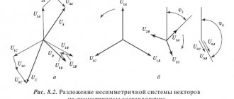
The vector diagram of a symmetrical three-phase EMF system is shown in Fig. 2.14. (It should be noted that when considering three-phase circuits, the complex plane is usually rotated by an angle counterclockwise.) From the vector diagrams in Fig. 2.14 it follows that for a symmetrical three-phase system the geometric sum of the EMF vectors of all phases is equal to zero: . An EMF system in which the EMF of phase B lags in phase behind the EMF of phase A, and the EMF of phase C in phase lags behind the EMF of phase B, is called a positive sequence system. If you change the direction of rotation of the generator rotor, the phase sequence will change and it will be called reverse.
The phase sequence determines the direction of rotation of three-phase motors; it must also be taken into account when switching on three-phase generators for parallel operation. To determine the phase sequence, there are special devices - phase indicators.
Since direct phase sequence is used in practice, this chapter will consider three-phase circuits with direct phase sequence only.
2.4.3 Connection methods for three-phase power supply
If the phases of the winding are not electrically connected to each other, then they form an unconnected three-phase circuit system. In this case, each phase must be connected to its receiver with two wires (Fig. 2.15). Unconnected circuits have not been used due to their inefficiency caused by the large number of wires connecting the power source and receivers.
So, for example, in a three-phase unconnected system there will be six such wires. More advanced and economical are coupled circuits, in which the phases of the winding are electrically connected to each other. In the future, we will consider connected three-phase circuits with a star or delta connection of winding phases, developed and put into practice by M. O. Dolivo-Dobrovolsky in the early 90s of the last century.
When the phases of a generator (or transformer) winding are connected by a star, their ends X, Y and Z are connected to one common point N, called the neutral point (or neutral) (Fig. 2.16). The beginnings of the phases are brought out to terminals designated A, B and C, respectively. Wires are connected to them, with the help of which the power source is connected to the receiver. These wires are called linear, and a three-phase circuit is called three-wire. In the case when the neutral point N of the power source is connected to the neutral point n of the receiver (see Fig. 2.19), the three-phase circuit will be four-wire. The wire connecting the neutral points N and n is called neutral.
When connecting the phases of the power source with a triangle, the corresponding beginnings and ends of the phases are combined (connected) into one point: XB, YC, ZA (see Fig. 2.16). In this case, the source phases are connected in series. Connecting the source phases into a closed triangle is not equivalent to their short circuit (as would be the case with a similar connection of the phases of sinusoidal current sources), since with a symmetric EMF system the sum of their instantaneous values is eA + eB + eC = 0. Therefore, during no-load current source phases does not occur. However, as will be shown below, in practice, the phases of three-phase generators are preferably connected in a star.
The voltages between the beginning and the end (or between the terminals) of each phase of the source uA, uB, uC are called phase, and between the same terminals of different phases - linear (uAB, uBC, uCA) (see Fig. 2.16).
In practice, they usually deal not with individual sources, but with several connected in parallel. In this case, we can neglect the internal resistance of the source phases, consider the phase voltages uA, uB, uC to be numerically equal to the phase EMF and depict them as a symmetrical system of vectors (Fig. 2.17). It should be noted that the system of phase and line voltages of the source is symmetrical due to the design features of the three-phase generator.
The conditional positive directions of phase voltages are taken to be the direction from the beginning to the end of the phases of the windings, and the linear voltages - from the beginning of one phase to the beginning of another (see Fig. 2.16). In accordance with the selected conditional positive directions of phase and line voltages (see Fig. 2.16), you can write equations according to Kirchhoff’s second law and construct a vector diagram from them:
uAB = uA – uB, uBC = uB – uC, uCA = uC – uA.
The complex values of line voltages are related to the complex values of phase voltages by the following equations:
, , .
Note that the equations make it possible to determine line voltages from known phase voltages. In accordance with these equations in Fig. Figure 2.17 shows a topographic (potential) diagram of the phase and line voltages of the source when its phases are connected by a star.
The diagram shows that for a symmetrical voltage system, linear voltages are represented by three vectors shifted in phase relative to each other by an angle ; in addition, the linear voltage vectors , , are ahead in phase, respectively, of the phase voltage vectors , and by an angle .
It is necessary to distinguish between the direction of the arrows in the diagram, indicating the conditional positive direction of linear voltages and the direction of vectors in the vector diagram. So, obviously, the vector must be directed to point A.
The magnitude of each of the linear voltage vectors is times greater than the magnitude of the phase voltage vector:
.
Attention should be paid to an important property of the linear voltage system: regardless of the nature of the load, the sum of their instantaneous values or vectors is always zero.
The rated voltages provided by GOST for low voltage receivers: Ul = 380 V and Uph = 220 V, Ul = 220 V and Uph = 127 V are related to each other by the indicated ratio.
The four-wire circuit allows the use of two power source voltages: phase and linear. When the source phases are connected by a triangle, the line voltages are equal to the phase voltages: Ul = Uph. As indicated, in practice, it is preferable to connect the phases of the windings of three-phase generators with a star, primarily because if the source EMF deviates from the sinusoidal shape due to the presence of higher harmonics, the sum of the instantaneous EMF values will not be equal to zero, and in the source winding connected by a triangle, in the absence of a load, currents that will cause it to heat up and reduce the efficiency of the generator.
3.2. Star connection of a 3-phase circuit.
In this case, the ends of the windings are connected at one common point O (zero point).
According to Kirchhoff's first law:
With symmetrical load ZA=ZB=ZC
and then
I0=0
. Since the current flowing through the neutral wire is zero, a neutral wire is not needed.
For a symmetrical load in a star connection, a 3-wire circuit can be used. This happens relatively rarely, for example when powering a 3-phase motor or transformer. A 4-wire circuit is more often used.
For lighting loads that are often asymmetrical, a neutral wire is necessary and therefore a 4-wire circuit is used.
1. Currents in connecting wires – I L
– linear currents()
2. Currents in loads - I Ф
– phase currents.
3. Load voltages – U Ф
– phase voltages.
4. Voltage between connecting wires – U L
– linear voltages.
In this scheme IЛ = IФ
.
UФ
Standard voltage: /D 380/220.
In the case of an asymmetrical load, a break in the neutral wire leads to a change in phase voltages and their asymmetry, which is unacceptable.
Typically, the neutral wire has a cross-section S/2 of the cross-section of the phase wires.
How is phase imbalance created?
A three-phase electrical network includes high-voltage and low-voltage parts. As a rule, at the boundary between these parts of the network, electrical substations with three-phase transformers are installed, which reduce the high-voltage voltage.
In the first half of the network, voltage imbalance is, in principle, unrealistic, because all three phase buses are loaded evenly. Therefore, electricity is transmitted through three wires, eliminating the need for a fourth additional conductor, which amounts to significant savings.
An electrical substation distributes energy between consumers. This part of the electrical network uses voltages up to 1 thousand volts.
Most often, an emergency situation in the form of a voltage imbalance occurs in this part, when the connected load is distributed unevenly between the phase buses or when the neutral conductor breaks. It is explained by the peculiarities of power distribution between single-phase electrical equipment.
Why do we need three-phase current?
Single-phase and three-phase alternating current are widely used in industrial and domestic applications. However, recently more and more consumers are choosing to abandon the former and are leaning toward the latter.
You might be interested in Features of the volt-ampere unit of power
And it's not even a matter of increasing power and including more electrical equipment. Sometimes the difference between the power load is not even noticeable, and under certain network parameters, the input power for both circuits may be the same.
The main consumer is three-phase equipment. This group includes:
- asynchronous electric drives;
- heating installations;
- industrial equipment.
The most common consumer of three-phase current is an asynchronous motor. It is as part of this network that they show the best operating parameters, high efficiency at relatively low energy costs.
Asynchronous motor
In addition, drives, heaters, boilers, electric furnaces, and heaters do not distort phases. For sensitive equipment, such subsidence is a very sensitive topic.
Note! In reality, it is impossible to provide the same load on all three phases. Accordingly, the voltage will always be different.
Since there are several more consumers in the room, an additional system is needed that can distribute the load evenly across all receivers. This requires a three-cable chain. The load is connected to the three-phase current network to the circuit that has the fewest consumers.
Three-phase current connection diagram
However, distribution systems for three-phase current circuits are very bulky and take up a lot of space. It requires additional security systems, since the voltage of such networks is 380 V. In the event of a short circuit, the current will be many times greater than with the usual 220 V.
Advantages and disadvantages
Like everything material, three-phase current has its pros and cons. The positive aspects of using systems with three or four wires include:
- efficiency. To transmit electricity over long distances, cores made of non-ferrous metals with low resistivity are used. The voltage is divided proportionally to the number of cables. By distributing loads, engineers can reduce the number of wires and their cross-section, which, given the cost of rare materials, provides noticeable savings;
- efficiency. The power parameters of three-phase transformers are an order of magnitude higher than single-phase transformers with smaller magnetic core sizes;
3-phase current transformer
- simplicity. When consumers are simultaneously connected to a three-phase system, an additional electromagnetic field is generated. The phase shift effect has made it possible to create simple and reliable brushless electric motors, the rotor of which is made according to the principle of a conventional blank and is mounted on ball bearings. Asynchronous electric drives with a squirrel-cage rotor are widely used as power units. The main advantage of such motors is the ability to change the direction of rotation of the axis by switching to different phase wires;
- variability. In circuits with several phases, it is possible to obtain different voltages. The user will be able to change the power of the heater or servo drive by switching from one cable to another;
- reducing the stroboscopic effect. It is achieved by independently connecting different lamps to individual phases.
You may be interested in this: How to check the mosfet (field tester)
Along with its advantages, three-phase current has its disadvantages. They include:
- connection difficulty. To connect a three-phase network to a private or industrial building, you must obtain special permission and technical specifications from the local energy sales company. This event is quite expensive and troublesome. Even if all conditions are met, a positive result is not always guaranteed;
- application of enhanced security systems. The three-phase network supplies a voltage of 380 V, so additional devices for protection against electric shock and short circuits are required, which can lead to fire. In such cases, another three-pole circuit breaker with higher ratings is installed at the input. It will help avoid fire in the event of a short circuit;
- the need to install auxiliary modules to limit overvoltage in the distribution board. It is necessary in case the neutral cable breaks, which will lead to an increase in voltage in one of the phases.
The transition to three-phase current is advisable for owners of premises whose area is more than 100 square meters. meters. This applies to private homes and industrial buildings. This connection scheme will allow you to redistribute the load evenly across all consumers and avoid power surges.
Why are there usually three phases and not four?
Almost all novice electricians ask this question. In fact, the number of phases is unlimited. There can be 1, 2, 3, 4 and even 10. However, three-phase systems are widely used. This is due to the fact that such a circuit is sufficient to solve most problems.
You may be interested in: Features of solder for soldering
Such systems are mostly used for power plants in production. The rotor rotation is 360 degrees, and the phase shift is 120 degrees. It is quite enough to spin the armature to the required speed and get the required power from the engine. Increasing the number of phases will only increase the cost of the installation itself, since it will require installing additional coils and connecting extra cables.
Important! Adding phases to the existing three does not increase the efficiency of the unit or increase its power. From a rational point of view, this only adds to the cost of installations while maintaining the same operating parameters.