Identification of damaged components in electrical networks and systems is carried out using protection. Such protection has a selective effect. Thanks to this feature, reliable and long-term operation of electrical equipment is possible, as well as the safety of its maintenance by technical personnel.
Selectivity
Main tasks of selective protection
Selectivity is a process that means selection (selection). This term is applicable to different industries and areas of human activity. For example, in chemistry, when chemical reactions occur, they talk about the selectivity index. In this case, the selectivity of chemical transformations is considered.
As for a person, his perception of the world around him, the choice of information, as well as its memorization are selective.
What is selectivity in electrical engineering, and why is it needed?
The tasks of electrical selective protection include:
- guaranteeing the safety of equipment and operating personnel;
- instantly identifying the location of the fault and disconnecting only the faulty section;
- reducing the negative effects of the accident on other components and parts of electrical appliances;
- minimizing damage to the faulty area;
- guaranteeing maximum continuity of operation of the electrical system;
- achieving ease of operation of electrical equipment.
In addition, selectivity reduces the consequences of short circuits and the load on the device.
System functionality
Selectivity functions include the following:
- Provides maximum safety to electrical devices and people who work with them.
- In a short time, it identifies and turns off those sections of the electrical network in which an error occurred. Electricity supply to the affected area will be cut off.
- Reduces the negative impact on electrical mechanisms resulting from the failure of some parts of the circuit.
- Helps reduce loads on installations consisting of several elements. Prevents the negative consequences of circuit faults.
- Provides a continuous supply of electricity without losses.
- Does not interrupt the workflow, making it more efficient when working.
- Responsible for maintaining the circuit if the tripping protective elements become unusable.
- Helps ensure high functioning of plants and mechanisms.
- It's easy to use and helps save money thanks to its cost-effectiveness.
Absolute and relative selectivity of protection
Considering in detail what selectivity is, there are two types of selective action.
Features of differential protection of power equipment
According to the degree of selectivity, protection is divided into:
- absolute;
- relative.
The blowing of fuses in the exact circuit where the short circuit occurred is called “absolute protection”.
The tripping of a circuit breaker close to where the fuse failed is called "relative protection".
Attention! We can say that absolute selective protection protects against internal (own) short circuits, and relative selective protection protects against external (neighboring) and internal short circuits at the same time.
Relative and absolute selectivity of protection
Types of selective connection schemes
Protective equipment is divided into several types based on selectivity. These include the following types of protection:
- full;
- partial;
- current;
- temporary;
- time-current;
- energy.
Overcurrent protection
Each of them needs to be discussed separately.
Full and partial protection
With such circuit protection, the devices are connected in series. In the event of an overcurrent, the circuit breaker that is closest to the fault will operate.
Important! Partial selective protection differs from full selectivity in that it operates only up to the set overcurrent value.
Current selectivity type
By arranging the magnitudes of currents from source to load in descending order, current selectivity is ensured. The main measure here is the limiting value of the current tag.
For example, starting from the power source or input, circuit breakers are installed in the sequence: 25A, 16A, 10A. All machines can have the same response time.
Important! There must be a high circuit resistance between the machines. Then they will have effective selectivity. They increase resistance by increasing the length of the line, including sections with a wire of smaller diameter or inserting a transformer winding.
Current selectivity
Time and time-current selectivity
What does time selective protection mean? A feature of this design of a relay protection circuit is that it is tied to the response time of each protective element. Automatic switches have the same current parameters, but have different time delays when triggered. The response time increases as you move away from the load. For example, the closest one is designed to operate after 0.2 s. If it fails after 0.5 s. the second one should work. The operation of the third circuit breaker is calculated after 1 second in case of failure of the first two.
Temporal selectivity
Time-current selectivity is considered very difficult. To organize it, you need to select devices from groups: A, B, C, D. Group A has the highest protection (used in electrical circuits). Each of these groups has an individual response to the magnitude of the electric current and the time delay.
Energy selectivity of machines
This protection is due to the properties of the switches provided by the manufacturer. Fast response - before short-circuit currents reach their maximum. Milliseconds count; it is very difficult to coordinate such selectivity.
Energy selectivity
What is zone selectivity
The determination of this coverage by selective network protection is related to the peculiarities of its construction. This is a rather expensive and complicated method. As a result of processing the signals coming from each switch, the fault zone is determined, and shutdown occurs only in it.
Information. To provide such protection, additional power is required. The signal from each switch is sent to the control center. Shutdowns are made by electronic releases.
It is most rational to use such circuits in industrial enterprises, where systems have high values of short-circuit currents and significant operating currents.
Example and graph of zone selectivity
Comparison of NSAIDs
Some NSAIDs have quite serious side effects, while others do not. This is due to the peculiarities of the mechanism of action: how drugs affect certain types of COX - COX 1, COX 2, COX 3.
In healthy people, COX 1 is found in almost all tissues and organs (for example, in the kidneys and gastrointestinal tract), where it performs its most important function. With the help of COX-synthesized prostaglandins, the integrity of the intestinal and gastric mucosa and adequate blood flow in it are maintained, the secretion of hydrochloric acid is reduced, the pH is increased, the secretion of mucus and phospholipids is ensured, and cell proliferation (reproduction) is stimulated.
NSAID drugs that inhibit COX 1 help reduce the concentration of prostaglandins not only in the inflammatory focus, but throughout the human body, resulting in the development of negative consequences.
In healthy tissues, COX 2 is usually found in small quantities or is completely absent. An increase in its level is observed directly during inflammation or in the inflammatory focus itself. NSAID drugs that selectively inhibit COX 2 are most often taken systemically, but their action is directed specifically at the site of inflammation, helping to reduce the inflammatory process there.
Despite its contribution to the development of fever and pain, COX 3 does not participate in inflammatory processes. The action of certain NSAIDs is aimed at this type of enzyme, but at the same time they have a weak effect on COX 1 and COX 2. According to some experts, COX 3 is not an independent isoform of the enzyme, but is a variant of COX 1, but this statement is not currently true confirmed by additional studies.
We advise you to study Personal protective equipment against electric shockCalculation of selectivity of machines
When considering the question of what selectivity is, it is necessary to have an idea of how it is calculated. Calculations come down to the correct selection of a protective device, in particular an automatic machine.
Selectivity for machines located close to the power source must satisfy the following condition:
Is.o.last ≥ Kn.o.* Ik. previous,
Here:
- Is.o.last – the value of the current that triggers the protection;
- Kn.o. – shutdown reliability coefficient;
- I part previous – short-circuit current at the end of the protection section.
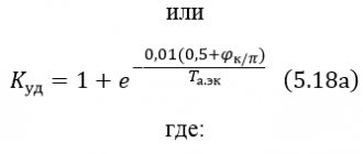
In the case of time dependence, the following formula is used to calculate selectivity:
Ts.o.last ≥ Tk.prev.+ ∆T,
Where:
- Tс.о.last and Тк.prev. – time intervals through which cut-off switches operate;
- ∆T – selectivity time point.
The selection of automatic switches for calculations is carried out according to the tables.
Machine selectivity table
Requirements for relay protection [edit | edit code]
Selectivity (selectivity) [edit | edit code]
Selectivity is a property of relay protection that characterizes the ability to identify exactly the damaged element of the electrical power system and disconnect this element from the serviceable part of the electrical power system (EPS). Protection can have absolute or relative selectivity. Protections with absolute selectivity only operate in the event of damage in their zone. Protections with relative selectivity can act in case of damage not only in their own zone, but also in the neighboring zone. And the selectivity of switching off a damaged EPS element is ensured by additional means (for example, a response time delay).
Performance [edit | edit code]
Speed is a property of relay protection that characterizes the speed of identifying and separating damaged elements from the electrical power system. An indicator of performance is the protection response time - this is the time interval from the moment the damage occurs to the moment the damaged element is separated from the network.
Sensitivity [edit | edit code]
Sensitivity is a property that characterizes the ability of relay protection to detect faults at the end of its established coverage area in the minimum operating mode of the power system. In other words, this is the ability to sense those types of damage and abnormal conditions for which it is designed, in any operating conditions of the protected electrical system. The sensitivity indicator is the sensitivity coefficient, which for maximum protections (responsive to an increase in the controlled value) is defined as the ratio of the minimum possible signal value corresponding to the monitored damage to the response parameter (setpoint) set on the protection.
Read also: UFO at home
Reliability [ edit | edit code]
Reliability is a property that characterizes the ability of relay protection to operate correctly and reliably in all modes of the controlled object under all types of damage and abnormal modes for which this protection is intended, and not to operate under normal conditions, as well as in such damage and violations of the normal mode, when for which this protection is not provided. In other words, reliability is a property of relay protection that characterizes its ability to perform its functions under any operating conditions. The main indicators of reliability are uptime and failure rate (number of failures per unit of time).
Principle of logic
To implement circuits using this principle, digital relays are needed. The relays are connected to each other by a twisted pair line, a fiber optic cable, or via a telephone line (using a modem). With the help of such lines, information is received (transmitted) to the dispatch console from different objects and between the relays themselves.
The principle of logic in a radial network
The given Picture 9 explains the principle of operation of the logic. Each of the 4 digital relays uses a current setting equal to the most recent sensitive stage. This stage has an operating time of 0.2 s. Logical selectivity implies the possibility of blocking the relay with a LO (logical standby) signal. This signal is supplied through the channel from the previous protection relay. Each of the relays can transmit such signals in transit.
As can be seen from the figure, during a short circuit at point K1, all other relays, from the LO signal supplied by relay K1, will be on hold. Relay K1 will operate and shut down. In the event of a short circuit at point 2, relay K4 will operate in the same way.
Such schemes for constructing logical control are demanding on the reliability of communication lines between elements.
Operation of relay protection [edit | edit code]
To ensure reliable and economical operation of power systems and power equipment, as well as uninterrupted power supply to consumers, power grid organizations carry out a set of organizational and technical measures to equip, operate and maintain relay protection devices, electrical automation, remote control and alarm devices, abbreviated as relay protection and automation devices, at a high technical level
.
In Russia, this activity is regulated by industry normative and technical documents, the main of which are:
- Rules for the construction of electrical installations (PUE)
- RD 153-34.0-04.418-98 “Standard regulations on relay protection and electrical automation services”
To implement the specified set of measures at all levels of management of the Russian electric power industry, relay protection, automation and measurement services
(RZAI service -
SRZAI
, RZAI service -
SRZAI
), in lower level divisions (production departments, electric network enterprises (PES)) - local RZAI services (
MS RZAI
), at power plants and cascades of hydroelectric power stations - RZAI services or
electrical laboratories
(
ETL
) .
The following basic requirements apply to relay protection:
· selectivity;
· performance;
· sensitivity;
· reliability.
1. Selectivity or selectivity is the ability of relay protection to detect the location of a fault and turn it off only by the switches closest to it.
Rice. 2.1. Relay protection of radial circuit.
Selective action is a relay protection action that ensures that only the damaged system element is disconnected. Thus, in relation to the radial network diagram shown in Figure 2.1, the requirement for selectivity of action is reduced to the fact that during a short circuit at point K1, only switch Q3 is turned off, and during a short circuit at point K2, switch Q2 is turned off.
Read also: Which electric stove to choose for the kitchen reviews
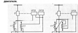
Let's turn to Fig. 2.2
During a short circuit at point K
1 (Fig. 2.2) to properly eliminate the accident, the protection on switch
Q
1 must operate and turn off this switch. In this case, the remaining undamaged part of the electrical installation will remain in operation. This selective action of protection is called selective.
If during a short circuit at point K
1before the protection of switch
Q
1, the protection of switch
Q
2 will act and turn off this switch, then the elimination of the accident will be incorrect, since in addition to the damaged electric motor M1, the undamaged electric motor M2 will remain without voltage
.
This protection action is called non-selective.
From Fig. 2.2 it is clear that if during a short circuit at point K
Q
acts incorrectly and turns off this switch, then the consequences of such a non-selective action will be even more severe, since both undamaged electric motors M2 and MZ will remain without voltage
.
In relay protection technology, it is customary to call the previous (lower) and subsequent (higher) protection on adjacent lines.
So in Fig. 2.2, switch Q
1 has the previous protection installed, and switch
Q
2 has the subsequent one. The numbering of protections starts from the protection furthest from the power source.
The considered example shows that fulfilling the selectivity requirement is of paramount importance to ensure the correct elimination of accidents.
Several methods are used to ensure selectivity.
Selectivity according to the principle of action . There are relay protections with absolute and relative selectivity.
Relay protections with absolute selectivity, in accordance with the principle of their operation, operate only in the event of damage to the protected element. Therefore, they are executed without any time delays. For example, gas (GZ) or differential protection of a transformer (DZT). The DZT fundamentally does not operate in the event of a short circuit outside the coverage area (for example, the coverage area of the differential protection is limited to the installation location of the current transformers supplying it).
Relay protection with relative selectivity. Relative selectivity is achieved by time detuning from adjacent sets of protections. Protections with relative selectivity can operate as backup protection in case of short circuit on adjacent elements. (for example, maximum current protection (overcurrent protection)). Such protections are usually performed with a time delay
Sensitivity selectivity . The current, voltage or response resistance is selected in such a way that subsequent protection does not operate in the event of a short circuit on an adjacent line or behind the transformer. For this purpose, for example, the current cutoff is tuned out from the short-circuit currents at the end of the line or behind the transformer and, therefore, has in sensitivity.
Time selectivity. The time delay of each subsequent protection, for example, maximum current protection, is selected to a selectivity level greater than the previous protection. Therefore, the subsequent protection does not have time to work, since it is ahead of the previous line protection in case of a short circuit on it. This principle is the simplest, but has a significant drawback, which is that the time delay increases as the short-circuit point approaches the power source. The value of the selectivity stage is determined by the accuracy of the protection time relay, the speed of the applied switch and for electromechanical protection it is 0.5 s, and for modern microprocessor protection it is 0.2...0.3 s.
Logical selectivity is applied if adjacent, as in the previous example, protections are united by a communication line. In this case, the subsequent protection will operate without a time delay (fast-acting stage), provided that the previous protection has not started. The start of the previous protection indicates that a short circuit occurred on an adjacent line and the subsequent protection is switched to time selectivity mode, i.e. it will work if the previous protection or its switch fails. It is advisable to use logical selectivity on short lines and when using digital relays that have a special “logical standby” input.
2. Performance is the property of relay protection to turn off damage with the minimum possible time delay, because rapid shutdown of damaged equipment or a section of an electrical installation prevents or reduces the extent of damage, preserves the normal operation of consumers of the undamaged part of the installation, and prevents disruption of the parallel operation of generators. Prolonged flow of short-circuit current can lead to damage to undamaged sections of equipment, lines, transformers through which short-circuit current flows due to thermal overheating of the equipment. The permissible time for current to flow through equipment without causing damage is indicated in GOST standards for equipment and is inversely proportional to the magnitude of the short-circuit current.
Performance is necessary for the following reasons:
1. During a short circuit, the power supplied by the generators of the station near which the short circuit occurred is sharply reduced. As a result, the rotation speed of the generators increases. If a short circuit is turned off by a protection that has a time delay, then by the time it is turned off, the generators of this station will be out of synchronism, that is, the generators will lose stability.
Read also: Antenna circuits for television reception
2. A short circuit in any element of the system leads to a decrease in voltage, a decrease in the torque of the SD and IM and their braking. When the motor short circuit is quickly turned off, it immediately returns to normal mode; their braking is not dangerous and does not disrupt the mechanical process, and in some cases remains completely unnoticeable. Disabling short circuits with a time delay can lead to their complete stop and disruption of the technological process.
3. Quick disconnection of a short circuit reduces the size of destruction of insulation and live parts by short circuit currents at the point of damage, reduces the likelihood of accidents.
4. Accelerating the disconnection of faults increases the efficiency of automatic reclosing and automatic reclosure, since the smaller the damage at the fault location, the higher the probability of successful operation of the automation.
The shutdown speed is limited by the inherent operating times of the relay protection and the circuit breaker, as well as by the conditions for ensuring selective operation of the relay protection. In general, the shutdown time is:
,
where is the intrinsic time of relay protection; – time delay set on the protection; – the switch’s own time, i.e. the time from the supply of a pulse to the trip coil until the start of the divergence of the arcing contacts of the circuit breaker; – arc burning time; – total switch off time.
For protections operating without a time delay, depending on the types of relays and switches, the shutdown time is equal to
Thus, with existing types of relays and switches, the lower limit of the short circuit tripping time can be 3...12 periods of current with a frequency of 50 Hz.
To ensure the stability of parallel operation, generators, transformers, power lines along which parallel operation is carried out and all other parts of the electrical installation or electrical network must be equipped with high-speed relay protection, the duration of which should not exceed 0.1 s, and for ultra-high voltage lines - not more than 0.02 s.
3. Sensitivity is the property of protection to operate reliably during a short circuit at the end of the protected section in the minimum operating mode of the system.
The protection must be so sensitive to those types of damage and disruptions to normal operation in a given electrical installation or electrical network for which it is designed, so that its action is ensured at the onset of damage. The sensitivity of the protection should also ensure that it works in case of damage in adjacent areas. So, for example, if, due to damage at point K1 (Fig. 2.2), for some reason the switch Q
1, then the protection of the switch Q2 next to the power source must operate and open this switch. This protection action is called long-range contiguous reservation.
The sensitivity of protection is assessed by the sensitivity coefficient (Kch)
, defined as the ratio of the minimum value of the controlled value during a short circuit at the end of the protected section to the protection setting.
Sensitivity coefficients are normalized by the PUE and their minimum value is for a short circuit in the protected area K
h
=
1.5, in the redundancy zone -
K
h
=
1.2, for high-speed differential protection
K
h
=
2.
The sensitivity coefficient takes into account the relay errors, the errors in calculating the parameters of the operation of the relay protection, the influence of the transition resistance and the electric arc at the fault location.
4. Reliability is the property of protection that is guaranteed to perform its functions throughout the entire period of operation. The protection must operate correctly and reliably to turn off equipment switches in the event of all damage and violations of the normal operating mode and not operate under normal conditions, as well as in the event of such damage and violations of the normal operating mode in which the action of this protection is not provided. The requirement for reliability is ensured by the perfection of protection principles and equipment designs, the quality of parts, ease of implementation, as well as the level of operation.
The required state of protection devices is maintained by scheduled checks of relay protection, during which it is necessary to identify and eliminate defects that have arisen. Modern microprocessor-based protection devices have built-in automatic and test systems that allow you to quickly identify emerging faults and thereby prevent failure or incorrect operation of the protection. The depth of such checks can be large, but not 100%. Therefore, the presence of test checks or automatic control does not eliminate the need for scheduled checks, but significantly reduces their frequency and scope.
Date added: 2017-04-05; ; ORDER A WORK WRITING
Directional principle
The arrangement of the machines and the further sequence of their operation are guided by the direction of the current. To do this, using the voltage vector, a point is specified, relative to which this vector receives a phase shift. According to this principle, the relay will be sensitive to both current and voltage. Such a circuit can be installed in both a switchable zone and a zone that cannot be switched off.
RCDs and switches are connected according to the directional principle
Important! To implement such circuits, voltage transformers are needed to use them to determine the direction of the current.
In the above figure, you can see that the protective device D1 and the circuit breaker it controls will respond to a short circuit at point 1, but not to a short circuit at point 2.
Principle of differentiation
It is used where circuits with high power consumers are used. These consumers include:
- electric motors and generators;
- power cables;
- bus assemblies;
- transformers and other converters.
In this solution, deviations of the phase and amplitude parameters of the current at various points are used. A deviation of such values at point A and point B, in section AB, is considered an emergency, and the equipment shuts down. The use of current transformers allows filtering from various extraneous electromagnetic processes.
The protection is triggered only in the AB section if IA>IB.
Differential selective protection of powerful equipment
Protection created according to the differential principle can be of two types: longitudinal and transverse.
Current selectivity
This type of selective protection is installed in each electrical circuit at its beginning. If a short circuit occurs in an electrical network consisting of these circuits, the current increases according to its impedance. In this case, the inductance limits the rate of current rise and there is a certain minimum value. This value is the protection threshold.
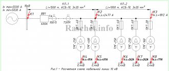
At the same time, protective devices can operate at slightly lower current values, if necessary. But the magnitude of the triggering current must be in the range of current values, which will be greater than in the case of a short circuit outside the protection coverage area. An example of current protection for a circuit with a transformer connected between cable power lines is shown in the image below:
The advantage of current selectivity is the ability to respond only to faults within the protected area and in connection with the consumer, excluding accidents outside the protected area. It is characterized by fast response, low cost and circuit simplicity. This is its advantage. The disadvantage is the difficulty of adjusting the selectivity of sequentially installed protection devices when they are located in neighboring areas due to the similarity of process parameters determined by emergency situations.
We advise you to study What is a voltage stabilizer
Selectivity map and rules for its creation
The diagram of the approved sample, on which all current parameters of protective devices and devices are plotted, indicating the common power source, is carried out on a scale convenient for viewing. This is a selectivity map. It ensures maximum use of the protective qualities of circuit breakers. All processes possible during operation are displayed graphically.
The following must be included on the map:
- places of important calculation points;
- protective characteristics of automatic circuit breakers and possible short circuits, while their min and max values are indicated.
This map serves as the basis for compiling a table for the selection of protective devices. In addition, the map allows you to evaluate the overall protective selectivity and provides complete information about the mutually agreed upon settings of all machines.
The map is constructed along axes. The abscissa axis represents current values, and the ordinate axis represents time values.
For your information. Other types of characteristics can be applied to the axis. Each scheme includes the parameters of two or three machines. The construction of such maps can be done using a computer program.
An example of a selectivity map made using the program
Properly executed selective protection allows you to preserve equipment. When a specific section is turned off, it allows you to turn the power back on using an automatic transfer switch (ATS) and minimize equipment downtime and interruptions in the supply of electricity to consumers.
Basic methods for ensuring selectivity
The devices are assembled into a single system in accordance with the main requirement - in case of any emergency or damage that occurs, the machine located at the closest distance from the fault must be activated, and all other devices are still in the closed position. An example could be a malfunction of a nearby outlet, when the switch of the outlet group in a certain room trips, but all other devices continue to be in working order.
It is necessary to determine in more detail the practically existing methods:
Current selectivity
A type in which there is a direct relationship between the current strength during a short circuit and the minimum distance from the fault site to the source - current selectivity. In practice, this method looks like this: on the power side, an automatic circuit breaker is installed with protection of a design that does not allow operation if a short circuit occurs in the load section. To turn off the machine in the event of a short circuit, it must be installed on the load side. A visual representation of this type of selectivity is shown in the figure below:
Temporary type
The response time is affected by the following type of selectivity - time. It is performed by installing the machine near the power source. In this case, the device closest to it will be triggered first in relation to the fault location. And everyone else will not be disconnected due to more time.
Zone selectivity
The blocking signal is transferred to a protection level with higher parameters automatically if the short circuit current setting is exceeded. The switch performs a test function until the same signal is triggered from the load side. This method triggers only in the event of a signal from the power side; all other devices will be in the on state.
The figure shows the process in schematic form:
Time-current selectivity
This type is of great relevance in all protective devices with time-current characteristics. The main principle of the type of selectivity under consideration is the need for the correct selection of switches with parameters that can ensure faster operation of the protection system on the load side. This should happen at any current parameters much faster than tripping the switch on the power source side.
An objective analysis of such a phenomenon is possible when considering the worst conditions. As an example, let's try to understand what is happening by allowing the switch on the supply side to operate along its own lower curve, and the device on the load side turns off at the very peak of the upper curve. An indispensable condition is that the response zones for both devices do not intersect in any way.
This is what it looks like in our specific case - there is a circuit that includes machines “A” and “B”. According to the specified selectivity parameters, it is necessary that at a current of the same value, device “B” is always triggered first.
In the figure above, you can see the most suitable arrangement of time-current curves for both machines.
In the presented image, you can see that at the same current value, device “B” will turn off first.
The operation of this device provides the necessary selectivity. The result of this process is that the bus supplying the reacting machine will remain energized.
You can avoid the negative consequences of overvoltage or short circuit and ensure high-quality protection of the wiring system using a proven method. Even at the design stage and in the process of planning electrical circuits and equipment, careful development is required with mandatory consideration of selectivity parameters.
Thus, the consumer has at his disposal the function of automatically determining the zone where the malfunction has occurred and locally shutting down a certain area without losing the functionality of the rest.
All equipment used is equipped with the most effective protection, which ensures the safety of people and significantly increases the service life of electrical wiring and household appliances.
← Previous page Next page →