Unbalance of three-phase voltages and currents
Asymmetrical modes are caused by three reasons:
- unequal phase loads of network elements caused by the operation of electric motors with unstable phase loads (for example, arc steel-smelting furnaces) and single-phase electric motors (this is especially noticeable in 0.4 kV networks, although in industry there are single-phase electric motors of sufficiently high power);
- incomplete-phase operation of lines caused by a short-term shutdown of one of the line phases during short circuits or a longer-term shutdown during phase-by-phase repairs, the presence of transverse reactors not in all phases of the line, etc.;
- inequality of phase parameters of lines. The slight difference in phase parameters is due to the difference in the location of the wires on the support. To equalize phase parameters on long lines and high voltages (330–750 kV), transposition of wires is carried out (alternately changing the arrangement of phases). The voltage asymmetry caused by this reason is an order of magnitude smaller than the first two.
The most common cause of voltage asymmetry in practice is the inequality of phase current loads. In this case, two types of asymmetry are distinguished: systematic and probabilistic asymmetry. A characteristic feature of systematic asymmetry is the constant overload of one of the phases; in this case, the phase loads are equalized by switching part of the loads from an overloaded to an underloaded phase.
Probabilistic asymmetry is characterized by alternating overload of one or the other phase (alternating asymmetry). In 0.4 kV networks of cities and rural settlements, voltage asymmetry is caused mainly by the fact that household electric power supplies, which are predominantly single-phase, are connected to these networks, and in networks of higher voltages - by the presence of powerful single-phase loads and three-phase loads among consumers, but with unequal consumption by phases. The latter include, in particular, arc steel-smelting furnaces. The current passing through the arc of each phase is determined by the distance between the electrode and the charge.
Collapses of the charge during its melting period do not allow maintaining equal distances in all phases and their currents turn out to be different. Another powerful source of asymmetry is the traction substations 275 U1A U1A a b U1C U1C U1B U2A U0A ϕ2 ϕ0 U2B U U0B 2C U0C U2C U0C UC U2B U1B U0A U0B UA UB of railway transport electrified with alternating current, since electric locomotives are single-phase power receivers.
Any asymmetrical system of three voltages can be decomposed into three symmetrical systems: positive sequence U1, the phase rotation of which coincides with the phase rotation of the original system, reverse sequence U2, the phase rotation of which is opposite, and zero sequence U0, all vectors of which are directed equally (Fig. 8.2) .
The system of phase-to-phase (linear) voltage vectors UBA, UAC, UCB is closed (formed into a triangle), so the zero sequence cannot be present in it. The system of phase voltage vectors UA, UB, UC is open in the presence of a zero sequence; the geometric sum of vectors is equal to triple the zero-sequence voltage.
The impact of an asymmetrical voltage system on electrical equipment is the same as that of three symmetrical systems. The essence of this effect on single-phase and three-phase EDs is different. For single-phase electric motors, only the voltage of the phase to which they are connected matters. Since the LV means in the CPU change the voltages equally in all three phases, the relationship between the voltages remains unchanged. As a result, the voltage deviation in all phases in some cases cannot be maintained within acceptable limits.
For three-phase electric motors (for example, three-phase motors), the impact is caused by the reverse phase rotation of the negative sequence voltage. Since U1 is significantly larger than U2, the motor rotates in accordance with the alternation of positive sequence phases, and the reverse has a braking effect on it.
Rice. 8.2. Decomposition of an asymmetric system of vectors into symmetric components
This causes a slight decrease in the rotation speed of the asynchronous motor (the slip s increases), but the rotation speed of the synchronous motor, naturally, cannot change. A negative sequence current occurs in the motor windings, the value of which is determined by the negative sequence resistance of the windings.
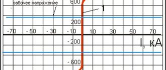
The resistance of the motor windings depends on the slip of the rotor relative to the stator s and is expressed by the dependence shown in Fig. 8.3.
During normal operation of an asynchronous motor, slip is small (s << l), for a synchronous motor s = 0, therefore the motor resistance xd is close to or equal to xc.
Rice. 8.3. Dependence of the resistance of an asynchronous motor on slip
For a stalled motor, s = 1, and the resistance drops sharply to xk. The ratio xc/хк determines the multiplicity of the starting current (usually kп = 4 – 7). When slip increases to s = 2 (the stator field rotates in one direction, and the rotor in the other, which is the case for negative sequence currents), the value of xd practically does not change compared to xk. This means that for negative sequence currents the motor resistance is kp times less than for positive sequence. Therefore, for example, when a negative sequence voltage U2 = 3% appears at the input of a motor with kп = 7, the negative sequence current in its windings will be 21% of the positive sequence current, which will cause their additional heating.
The classical recording of the equations of connection between vectors U A, U B, U C and vectors U 1, U 2, U 0 of symmetric components has the form:
where the factors a and a2 represent operators for rotating vectors by 120° and 240°.
Equations (8.5) are written for phase voltage vectors, the order of which the real axis passes is UA, UB, UC. The order of passage of the real axis of the vector xd xс xк s 1 2 mi of phase-to-phase voltages has the form UAB, UBC, UCA. For phase-to-phase voltages in the given formulas, the values are replaced in accordance with their sequence given.
A vector, as is known, is characterized by two parameters: the module and the angle of its location on the plane. The use of formulas (8.5) to calculate symmetrical components involves measuring not only the voltage magnitudes, but also the angles between their vectors. This is carried out by special devices that record the moments of transition of instantaneous phase voltages through zero. Angle measurement errors add to the voltage magnitude measurement error and degrade the overall measurement accuracy. Errors in measuring angles increase in the presence of higher harmonics in the network (sometimes numerous zero crossings occur at a point close to zero) and under sharply changing loads, leading to instability of the period of the fundamental frequency (see paragraph 8.1.1). Metrological standards recommend that when measuring the moments of transition of instantaneous phase voltages through zero, measures should be taken to suppress higher harmonics. In addition, in the practice of operating networks, linear and phase voltages are measured not using expensive special instruments, but using ordinary voltmeters. In this case, the angles of location of the vectors on the plane remain unknown.
However, this problem seems artificial. Angle measurements are not necessary if all parameters of the symmetrical components, including the shift angles between them, can be determined using strict algebraic formulas based on measurements of only stress moduli. Such formulas are given below (the conclusions are given in Appendix 6).
The voltage parameters of positive and negative sequence of phase-to-phase voltages are determined by the formulas:
where the angle ϕ2 is the angle of the vector U2 with respect to the vector U1.
In formula (8.6), the symbols a2, a4 and a22 denote, respectively, the sum of squares of linear voltages, the sum of fourth powers and the sum of pairwise products of squares. When determining U1, the “+” sign is taken in the numerator of the radical expression (8.6), and when determining U2, the “–” sign is taken. If the denominator (8.7) is negative, then 180° must be added to the angle ϕ2 determined by (8.7). 278 V adj. 6 also shows other algebraic expressions for the direct and reverse sequences, giving absolutely identical results.
Direct and negative sequences in phase voltages are determined based on the ratios: U1ph = U1 / 3 and U2ph = U2 / 3. The angle ϕ2ф between U2ф and U1ф is related to the angle between U2 and U1 by the relation ϕ2ф = ϕ2 + 60°. Zero sequence parameters cannot be determined based on measuring only phase voltages - it is necessary to use the values U1, U2 and ϕ2 already obtained for phase-to-phase voltages and calculate auxiliary quantities from them:
Then calculate the value
After this, the zero-sequence voltage parameters are determined using the formulas:
The given formulas are exact algebraic expressions, since they were obtained without assumptions. In computer data processing, the complexity of formulas does not matter, so it is not recommended to use approximate formulas. In addition, symmetrical components also have to be calculated for currents, and in them the negative and zero sequences have much higher values than in voltages. Therefore, the assumptions made when deriving approximate formulas for voltages (for example, neglecting obviously small values) may turn out to be unacceptable when using these formulas for currents.
In evaluation calculations, the positive sequence can be taken equal to the average value of the three measured voltages, and the reverse sequence - equal to 62% of the difference between the highest and lowest values of phase-to-phase voltages. In phase voltages, usually U0 >> U2ph. In this regard, the value of U2ф can be neglected. Then the value of U0 can be taken equal to 62% of the difference between the highest and lowest phase voltages.
When making accurate calculations, it is necessary to keep in mind the problem of matching phase and phase-to-phase voltages. The three phase-to-phase voltages obtained as a result of measurement always “add” into a triangle, even if measured with an error (the exception is the almost unrealistic case when the sum of two voltages is less than the third). Consequently, any obtained voltage values can be associated with a physically existing system of phase-to-phase voltage vectors. Due to the inevitable errors in measurements, it will differ from the real system, but nevertheless will physically exist. At the same time, the measured phase voltages can never form, together with the measured phase-to-phase voltages, a physically existing system of six voltages. In Fig. 8.4, a shows the situation when the measured phase voltages do not fit into the system of phase-to-phase voltages, and in Fig. 8.4, b – when they “do not reach” each other. For any, no matter how small,
Rice. 8.4. Systems of asymmetrical linear and phase vectors
measurement errors, the zone of uncertainty in the location of the zero point (convex or concave triangle 0AB – 0BC – 0CA) will always exist. Since the measured voltages are essentially random variables within the range of measurement error, and the probability of a random variable hitting a point is identically zero, it is theoretically impossible for a combination of measurement errors to occur such that the vectors of all three phase voltages exactly converge at one point.
In Fig. 8.4, c shows the difference in the position of the zero point, determined by different pairs of phase voltages for the case shown in Fig. 8.4, b. Obviously, calculating the symmetrical components for a physically non-existent system is meaningless, so it is necessary to balance the measurement results. Formulas for calculating balanced voltages are given in the appendix. 6.
The relationship between voltages in nodes, currents in the line and resistances of various sequences is expressed by the formulas:
In the absence of currents I2 and I0, the voltages in the nodes are determined only by the positive sequence mode, since U2 = U0 = 0. If the phase parameters are unequal, even in the case of a symmetrical three-phase load (I2 = 0 and I0 = 0), voltages U2 = Z21 I1 and U0 arise = Z01 I1 .
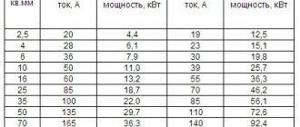
The equality of phase parameters is violated when the line phase is disconnected or (albeit to a much lesser extent) in the absence of transposition of phase wires on the line or its cycles are extended. In table 8.1 shows the values of the mutual resistance of the sequences for non-transposed lines. The negative sequence voltage at the receiving end of such a line will be 8–10% of the positive sequence voltage loss. An asymmetrical voltage system also occurs on the consumer buses powered from areas located within the complete transposition cycle.
Table 8.1
Line parameters 110–750 kV
* Characteristic impedance and natural power are determined by the formulas: 2 nat /; /. xb PU ρ
Consequences of phase imbalance
The consequences of phase imbalance are manifested in an increase in power consumption from the network; in the incorrect operation of electrical receivers, their malfunctions, failures, shutdowns, blown fuses, and wear of insulation.
Conventionally, the negative consequences of phase imbalance can be divided into three groups:
1. Consequences for electrical receivers (devices, equipment) associated with their damage, failures, increased wear, and reduced service life.
a) consequences for single-phase electrical consumers Low voltage causes incorrect operation of single-phase consumers: dim light of lighting devices, prolonged heating of heating devices, prolonged start-up of motor devices, computer malfunctions, etc. High voltage causes failures of electrical receivers due to wear of the insulation, switching them off by protective devices, and blown fuses.
b) the consequences of phase imbalance for three-phase power consumers. The main part of three-phase consumers (consumers powered by line voltage) are electric motors that drive submersible and sewage pumps, automatic gate drives, machine tools, etc. The control and monitoring system for the launch of such three-phase consumers, as a rule, is connected to phase voltage. In case of phase imbalances, the launch control system (CLS) of the electric motor, which controls the duration and fact of launch, operates unstably, i.e. spontaneously issues commands to start or stop it. The range of changes in phase voltage is strictly regulated by the operational documentation (as a rule, a skew of more than ± 7.5 ÷ 10% of the nominal value is not allowed). If the skew exceeds the permissible limit, the control system fails. When the phase voltage level is restored, the next start occurs, and so on. It is known that the “start-up” mode of an asynchronous motor is characterized by short-term operation of the stator windings in short circuit (short circuit) mode, i.e. When turned on, the engine consumes much more energy than during operation. Naturally, frequent restarts will cause significant overheating of the insulation and significantly increase power consumption from the network. Possible negative consequences of this mode of operation are either failure to start or equipment failure due to burnout of the motor windings.
We advise you to study Choosing a night light for the nursery together
2. Consequences for electricity sources: increased energy consumption, increased electricity losses when powered from the state grid; when powered from a three-phase autonomous source - mechanical damage (damage to shaft bearings, bearing shields of the generator and drive motor, coking of injectors), reduced service life of the source, increased wear, increased consumption of fuel, oil, and coolant.
3. Consequences for consumers related to safety, since deterioration in the quality of insulation can lead to: - electrical injuries; - fire of electrical wiring or electrical receivers; as well as consequences associated with increased costs for: - electricity; - consumables for the generator; - repair of electrical receivers damaged due to phase imbalance; - purchase of new electrical receivers that failed due to phase imbalance.
Causes
In most cases, this emergency mode is caused by uneven load distribution - when one or two phases are overloaded. In this case, high current consumption on them leads to an inevitable increase in voltage on other phases.
Often, the cause of network voltage asymmetry is an open-phase mode, which is dangerous not only for loads with a supply voltage of 220 V, but also for three-phase equipment. Thus, the absence of one phase in the line can lead to an increase in currents in the others.
Broken neutral wire. The mode of operation of the line in the absence of a working zero (N) can be classified as single-phase. Violation of the load current ratio in such cases inevitably causes a change in phase voltages (Uph). Voltage deviations depend on the load power ratio between phases. In some cases, Uph can reach linear values (380 V).
Short circuit of one of the phases with the working neutral (“zero”) and the failure of the circuit breaker for some reason (malfunction, large length of the line section between the short circuit point and the circuit breaker, etc.). In this case, Uph also increases on other conductors.