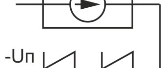
Operating principle (current stabilizer operation)
Let our load be R, we will assume that its resistance almost does not change (R = const), we want the current unchanged (I = const), and what remains for us is only the output voltage at the current source, this is what the circuit will select , and not just from the bulldozer, but precisely one in which exactly the current I for which the device is designed will flow through the above-mentioned load R.
And here is an analysis of the operation of the circuit itself:
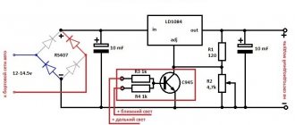
after connecting the power source, the field-effect transistor opens through resistor R1, current flows through resistor R2—the open drain-source channel VT1—and the load (LED). The higher the current, the more the voltage across the resistor will drop, and when it reaches the opening value of VT2 (for silicon bipolar approximately 0.60-0.75 V), it will open, current will flow through its EC from the minus to the gate of VT1, thereby closing it, but not completely, because R1 is not going anywhere.
Note. Parts for this instance were taken from old boards, in particular, a powerful field-effect N-channel transistor MTD20N06V in DPAK (TO-252) version from the motherboard, it has an open channel resistance of 65 mOhm, and a maximum long-term applied gate-source voltage of 20 Volts, which powers the circuit from the power supply 12 Volts (voltage surges no more than a few Volts), so a Zener diode is not needed. The bipolar transistor is the well-known BC847A in a SOT-23 package. Resistor R1 = 11 kOhm , R2 = 2 Ohm , size 1205 and power 0.25 W. This instance is designed for stabilized current:
Istab = UBE * R2 = 0.6 V / 2 Ohm = 300 mA
Nuances of calculating a current stabilizer
The stabilizer is calculated based on the stabilization voltage U and current (average) I. For example, the voltage of the input divider is 25 V, the output needs to be 9 V. Calculations include:
- Selection according to the zener diode reference book. Focus on stabilization voltage: D814V.
- Finding the average current I using the table. It is equal to 5 mA.
- Calculation of the supply voltage as the difference between the stable voltage of the input and output: UR1 = Uinx - Uout, or 25-9 = 16 V.
- Dividing the resulting value according to Ohm's law by the stabilization current according to the formula R1 = UR1 / Ist, or 16/0.005 = 3200 Ohm, or 3.2 kOhm. The element rating will be 3.3 kOhm.
- Calculation of maximum power using the formula PR1 = UR1 * Ist, or 16x0.005 = 0.08.
The zener diode current and the output current pass through the resistor, so its power should be 2 times greater (0.16 kW). Based on the table, this rating corresponds to 0.25 kW.
Self-assembly of a stabilizer for LED devices is only possible if you know the circuit. Beginners are recommended to use simple algorithms. You can calculate an element’s power based on formulas from a school physics course.
Trial
The tracks were drawn with a marker, so the board is slightly different from the designed one; fastenings for the screws were not made.
We connect the device to a power source (I had a 12V transformer with a diode bridge and a capacitor), now knowing that the current is relatively small, I stupidly shorted the output with an ammeter designed to measure direct current up to 20A, the readings are below: This is an adequate result for such a circuit. Next, two 10 W LEDs with different supply voltages were connected in turn. For an LED with one crystal, the voltage output was Uout = 2.72 V at a current Iout = 0.31 A, while at the input Upit = 10.88 V, i.e. dissipates approximately:
P1 = (Upit - Uout)*Iout = (10.88-2.72)*0.31 = 8.16*0.31 = 2.53 W
For the second LED, in which three crystals are connected in series Uout = 10.32 V, Iout = 0.29 A at Upit = 11.22 V, we obtain:
P2 = (Upit - Uout)*Iout = (11.22-10.32)*0.31 = 0.9*0.31 = 0.279 W
When the input voltage differs as little as possible from the required supply voltage to provide the required current, then high efficiency is achieved (with a second LED η = 92%) with ease of implementation.
Let's replace the resistor that determines the output current of the current source with 470 Ohms, then we get the output current:
Iout = UBE/R2 = 0.6 / 471 = 1276 µA
Ammeter test:
Thus, with a 12 V power supply, we connect a 5 mm LED, a current of ~1.3 mA passes through it, through two/three LEDs the current will be the same, because the supply voltage is enough for this.
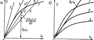
I also made a small graph of the dependence of the output stable current on the supply voltage of the current stabilizer. First, the rated current is reached (when the supply voltage is not enough for Ist), and then everything is fine, when the voltage changes three times (from 10 to 30 V), the current changes by only 0.64 mA or 4.22%.
Current stabilizer on a transistor
However, this approach is not suitable in all cases (a high voltage is required on the power source, and at high current the resistor will heat up considerably). The simplest diode stabilizers have similar problems.
The most logical way to control current is with transistors. We will dwell on them below. This approach is beneficial not only from the point of view of saving on the cost of component elements, but also from the point of view of fine-tuning the circuit to suit your needs (for example, circuits on ready-made microcontrollers cannot change the output parameters in the required range, they operate only within fixed limits, which means changing to suit your needs will be difficult, since it is necessary to use additional elements to control the current level).
The use of current stabilizers on a transistor
Where might you need stable current? Most often these are power schemes:
1. LEDs (car headlights, lighting strips, advertising boards, New Year’s garlands),
2. Soldering stations,
3. Chargers (for household batteries, car batteries, etc.),
4.Etc.
Current stabilizer circuit using one transistor
Rice. 2. Current stabilizer circuit using one transistor
The operating logic is very simple:
1. The current is leveled by high-resistance resistor R2 (about 200 Ohms), and the master one is low-resistance resistor R1 (1-10 Ohms).
2. The R2 D2 connection is used as a voltage divider, only a zener diode is used instead of the second resistor (it provides additional stabilization of the control current based on the transistor).
3.In normal mode, the current passes through the load practically unchanged.
4. When the current at the base of the transistor changes, the output current at the cathode will also be leveled; it will remain slightly sensitive to fluctuations at the emitter. That is, sufficient current will be supplied to the load even if the voltage at the power supply fluctuates.
Resistance R1 can get very hot during operation, so this element is best made from several resistors. The latter should be insensitive to temperature conditions. It is R1 that sets the output current, so the key parameters of the entire circuit will depend on its calibration.
Resistance R2 can be replaced with a variable resistor to adjust the saturation threshold of the transistor. This way you can adjust the output current level.
The diode (zener diode) D1 can be replaced with a resistance.
As a bipolar transistor, you can use one KT818 or a bunch of several connected according to a composite transistor circuit.
The specified circuit is suitable for stabilizing currents in the range of 0.5-5 A at a supply voltage from 9 to 45 V.
Circuit with two transistors
This method of connecting transistors is also called “current mirror”.
The diagram looks like this.
Rice. 3. Circuit with two transistors
In fact, here transistor VT2 has a base and collector connected to each other, so its functionality is comparable to a classic diode.
In fact, the identity of the parameters of both transistors makes it possible to better control (level) the collector current on the main element VT1. Otherwise, the logic of operation is similar to the previous circuit (on one transistor with diode division).
Increased stability
During operation, part of the energy is dissipated, the board and circuit components heat up, the parameters fluctuate, and most importantly, the saturation voltage (UBE) of transistor VT2 changes, the same ~0.7 V will change, which will lead to a change in the output current.
TKN ( Temperature Voltage Coefficient pn junction of the transistor is negative; with increasing temperature, UBE will decrease . For thermal stabilization, we introduce an additional element with a positive TKN - a zener diode (with Ust > 6.5 V), then when heated, the voltage on one component (VT2) will decrease, and on the other (D1) will increase, thus compensation is obtained. Ideally, the TKN of both devices should be equal in magnitude and opposite in sign, and heating should occur equally (that is why they are located next to each other on the board).
Another transistor VT3 has also been added, which acts as a current source for VT2, which will give even greater stability, because when the supply voltage changes within a certain range, the base current of VT2 will hardly change.
Printed circuit boards
Silkscreen only: pcb_current_source_silk.pdf Tracks only: pcb_current_source_solder.pdf Tracks and silkscreen: pcb_current_source_solder_silk.pdf Silkscreen only: pcb_current_source_silk.pdf Tracks only: pcb_current_source_improved_solder.pdf Tracks and silkscreen: pcb_current_source_improved_solder_silk.pdf
Everything fits on a small piece (3 by 2 cm) of foil PCB, heat is removed by attaching the entire board to a piece of aluminum with screws, it is designed with M2 fasteners in mind to easily and reliably fix it or simply glue it to the heat sink with heat-conducting glue (Stars 922) . If necessary, it can be easily reduced by almost half.
List of components
| Designation | Description | Buy on Aliexpress |
| VT1 | Powerful field effect transistor | 10pcs 2SK3919 TO-252 K3919 TO252Price: 0.98$ + 0.32$ = 1.3$ |
| VT2 | Low power transistor | 100pcs/lot BC847B SOT-23 BC847 SOT SMD 847B SOT-23Price: 0.79$ |
| R1, R2 | Resistors 1205 0.25 W (pack of 660 pcs.) | 1206 SMD Resistor Kit Assorted Kit 1ohm-1M ohm 1% 33valuesX 20pcs=660pcsPrice: 3.20$ |
| Thermally conductive adhesive Stars 922 | Star-922 Thermal Paste Thermal Grease Silicone Price: 1.54$ |
In the end
Such a conditional current source can be used as a current stabilizer for LEDs in a car (12 V-14.4 V), using it to connect lasers to some kind of transformer or UPS with a jumping voltage of several volts, or use it in charger circuits. But, as you understand, this device can be used with any other load that requires a stable electric current. This stabilizer dissipates “extra” energy in the form of heat, which may be unacceptable in situations where the voltage difference is large and the flowing current is not small, but, for example, in conditions where the input voltage does not greatly exceed the output voltage and the stabilization current is small, why not? ?
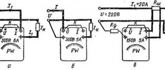
Electromechanical AC stabilizers
Electromechanical type stabilizers
Minsk refrigerators will simply stop if the voltage drops below nominal. This is relevant in a garage, in a country house, where the network parameters are not monitored too strictly, where welding machines and other powerful consumers are often used. Only in a school physics course does the voltage in a parallel circuit remain constant. In reality, the power of the source is limited, and if a neighbor decides to use welding, there will not be enough for everyone. Hence the flickering of light bulbs. The voltage jumps, but the spiral is uniform. For this reason, different power is released, which is noticeable visually. The spiral has a large inductive reactance (so that it does not burn out when turned on), but in practice the light power flux density directly follows the voltage in the network.
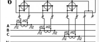
If a three-phase voltage stabilizer is considered a production necessity that protects against equipment breakdown, in everyday life it is necessary to use such devices in places where the network does not meet the standards. We illustrate a typical AC stabilizer using the example of electromechanical varieties of the above devices:
- There is an indispensable filter at the entrance. Most often throttle, not every owner is rich in grounding.
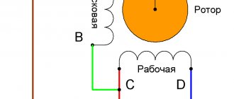
- The heart of a 220V electromechanical voltage stabilizer is a transformer. The difference between Resant is three phases - there are already three hearts inside. Each is responsible for its own phase. The key feature of transformers is the fact: the output winding along the ring is cleaned to a shine; a current collector in the form of a graphite brush slides there. Much more often there are two brushes. They are connected in parallel and are needed to increase reliability and reduce the thermal load on each individually.
- The location of the brush determines the length of the output coil, the number of turns and the voltage removed. On top of the sliding part is equipped with a substantial radiator made of silumin or a material of a similar nature to dissipate heat. The brushes run in a circle, more precisely, in a sector, depending on the angle of rotation of the shaft. Driven by an electric motor.
- The output part is equipped with an output voltage filter.
AC stabilization circuit
To find the angle of rotation of the brush block, a measurement circuit is known and is involved in estimating the parameters of the input voltage. Depending on the behavior of the network, the motor moves the brushes in the selected direction. As a result, the output voltage remains approximately constant.
The technical characteristics of electromechanical stabilizers are encouraging. In terms of stability, these are market leaders. Due to the large number of turns in the sector of movement of the brushes, it is possible to achieve excellent performance. The disadvantage of such a stabilizer is its relatively large mass, and its dimensions are also poor. In terms of operation, carbon settles on the conductive part, causing conductivity (in a useful sense) to deteriorate. In addition, the brushes spark. This is an inevitable defect that can be eliminated using a variety of methods.
The design of the 220V electromechanical voltage stabilizer is simple. The need for cleaning is determined by frequent activation of the protection circuits. Typically, the transformer is protected from overheating by bimetallic sensors. Consequently, if excessive heat is generated, the operating cycle of the device will begin to be characterized by increasing pauses for cooling. This indicates that it is time for maintenance. Remember, adjacent turns of a transformer are isolated from each other. If there is an excess of coal dust, a short circuit will form, which will negatively affect the heat generation and reduce the accuracy of the device, which is 2% of the nominal value.