marazmPRO2 › Blog › Wattmeter 60V 100A from China
We will talk about a Chinese measuring device, calling it a wattmeter is not entirely correct, because the device is multifunctional and measures not only watts, but also amperes, watt/h, ampere/h... The device is essentially a multimeter that measures everything at once
. and in addition to measurements, it makes calculations of energy consumption and can accurately calculate the battery capacity (both when charging and discharging).
The wattmeter is connected to an open DC circuit with a voltage of up to 60 Volts and is capable of passing through itself a huge current of up to 100 Amperes (I briefly passed more than 300 A, but the device turns off at this current), often such a current cannot be measured with a conventional multimeter (tester), you can, of course, use current clamps with the function of measuring direct current (I have a Mastech MS2108) but then the measurement accuracy will not be great.
So, as I said, the device must be connected in series to the circuit between the voltage (current) source and the consumer.
SOURCE side
— current source connection side (input)
LOAD
— load connection side (output)
The sides are labeled on the device itself, but the wires are not marked in any way and, moreover, are of an indecently short length.
I solved the problem immediately by disassembling the case and resoldering the wires into longer ones and making crocodiles at the ends for convenience (there is no photo, but everything can be seen in the video)
First of all, I use this device to measure the capacity of batteries. Sometimes this is the only way to determine the residual capacity of an old battery and understand how much Ah it has lost over its service life. Also, based on the ammeter readings, you can immediately determine whether the battery is charging or the charging process has already been completed and the charging current has dropped to zero or the charging process has not even begun. During the use of the device, five batteries were restored and two were given a disappointing diagnosis. In addition to measuring the capacity of the battery, I use the device to check the true power of certain devices, for example the same Chinese lamps or power supplies... a couple of times I even returned money for St. diode lamps that did not match the power from the description.
The device also has the function of recording all maximum values, but does not have the function of turning off the load when the power supply voltage drops. This would be convenient when discharging the battery and checking it for residual capacity, but you have to “catch” the lower value of the battery voltage (usually 10V) so as not to subject the battery to a deep discharge. Also, the device does not have a timer, so you need to time it yourself.
The only disadvantages I can mention are the short wires, which are inconvenient to connect, and probably the absence of any fuse. The fact is that there were cases when, through negligence, I shorted the load wires, thereby creating a short circuit with a current of 300A (the source was a 70A/h battery), the wires burned and thought that everything was ruined by the device, but partly when the short circuit was eliminated, the device rebooted and continued to please with its trouble-free operation, but still it would not hurt to have some kind of fuse.
How to connect
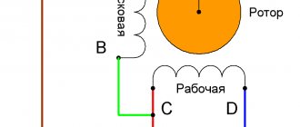
The accuracy of the information received depends on the correct connection of the wattmeter in a specific part of the electrical circuit. The proper connection diagram for a wattmeter will look like this: the stationary coil of the wattmeter is connected in series to the load or electricity consumers.
The moving coil is connected with an auxiliary resistance, and then the entire section is connected in parallel to the load. The movable section of the device in question has a certain rotation angle.
Since the circuit uses additional resistance, the electrical circuit of the device has virtually constant resistance. Power is determined directly by this indicator.
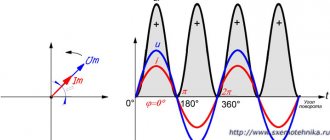
In such a device, a measurement scale is uniformly applied, which is made in a 1-sided version, when the position of the divisions continues from 0 to the right. When the electric current changes its own direction, this leads to changes in the direction of rotation and rotation of the active coil. When the device in question is connected incorrectly and the direction of the current is different, the electrical device will not work.
You may be interested in Voltage measurements with a multimeter
Because of these factors, the clamps used for connections should not be confused. The series winding has a clamp that connects to the power source. A parallel electrical circuit is called a generator circuit; it has its own terminal for connecting a fragment to a wire that is connected to a series coil.
Important! When properly connected, the currents in the wattmeter coil from the generator terminal are directed to the non-generator terminal.
Connecting a wattmeter
Microchip PIC18F252
Everyone has probably ever thought about the question of how much a particular household electrical appliance consumes. For example, how much energy does a TV consume in standby mode? How does the energy consumption of a refrigerator change in different operating modes? For these purposes, you will need an AC wattmeter, and in the article we will look in detail at the design of one of the device options (Figure 1).
| Picture 1. | Digital AC wattmeter. |
It makes no sense to develop such devices for direct current due to the fact that in this case everything is very simply calculated using known laws and mathematical formulas, and only an ammeter is required from the measuring instruments. For alternating current, everything is a little more complicated and previously analog wattmeters for alternating current, although they provided high accuracy, were difficult to manufacture, not to mention digital wattmeters and the ability to assemble such devices at home. Modern technologies and element base make it possible to design multifunctional devices at minimal cost. Cheap microcontrollers (MCUs) with rich peripherals and powerful computing capabilities significantly simplify the creation of various automation and control systems. Integrated precision analog peripherals, and in some microcontrollers a digital signal processing subsystem, make it possible to develop multifunctional measuring instruments.
The digital wattmeter, the design of which we will consider, is designed to measure the power consumption of devices connected to an alternating voltage network of 207 - 235 V / 50 Hz. The main element of the wattmeter is an 8-bit PIC microcontroller from Microchip PIC18F252 series, which, using external ADCs, measures the current flowing through the load, the voltage across the load, calculates the effective value of the voltage (effective value) in the network, the effective value of the current and the average value of power consumption. All specified parameters are displayed on a two-line character LCD indicator.
The device does not have a separate power source. A built-in mains power supply is used, due to which the microcontroller part of the device is completely isolated from analog nodes that are under mains voltage.
Best models
There are a large number of such measuring instruments on the market from European and domestic manufacturers. Each of them has its own advantages and disadvantages. It is necessary to study the most popular models in detail.
You might be interested in Features of using welding machine circuits
ROBITON PM-1
A device that helps control the consumption of electrical energy from the electrical network by 1 consumer. It combines in one housing a plug, a socket, an electrical unit and a monitor that reads the received data.
Makes it possible to calculate the power of a single load connected through the device. The wattmeter determines the amount of energy used over a specific time period and calculates the price of the electricity used.
Pros:
- compact size, simplicity, reasonable price;
- ability to work with any household devices;
- the ability to determine the amount of energy that is consumed by the heater.
Minuses:
- zeroing is poorly thought out;
- only works in warm conditions.
ROBITON PM-1
HiDANCE 3680W AC Power Meter
Compact household electronic device with advanced functionality. Makes it possible to determine the strength of alternating current voltage. Power consumption and its coefficient are calculated.
There is a function for determining the price of energy used. The device is convenient when testing household appliances, electrical appliances and heaters of any type in order to calculate economic efficiency.
Pros:
- bright design, neat assembly of the digital device;
- high-precision measurements, the result is clearly displayed;
- a large number of modes.
Minuses:
- it is necessary to enter the cost again after resetting the information;
- welded fork pins.
HiDANCE 3680W AC Power Meter
Espada TSL 1500WB
An easy-to-learn and use wattmeter that tests household appliances based on the level of energy consumed. Extremely convenient for checking electricity consumption when choosing a heater. The device shows the real power, expenses and price of electricity in the shortest period of time.
Helps calculate thermal efficiency and costs throughout the heating season. There is an option to enter information for a 2-tariff meter. The product signals an emergency situation or excess current or power.
Pros:
- high-precision product, measurement speed;
- the monitor is illuminated, large numbers;
- electricity price calculation.
Minuses:
- inconsistent backlight;
- Difficult to change power source.
Espada TSL 1500WB
TP-Link HS110
The device controls and takes measurements at a distance via a network using a smartphone or other electrical device. There is an option to automatically connect or turn off energy consumers.
Monitoring over a distance of electricity consumption makes it possible to select the appropriate mode of operation of household appliances or heating systems. A wattmeter helps set the required power.
Pros:
- remote control option;
- compact size, works with any household appliance;
- adequate cost.
Minuses:
- sensitivity to network quality.
TP-Link HS110
List of components used
| Designation in the diagram | Name, denomination | Housing, note |
| U1, U2 | 78L05 | SOT-89 |
| U3 | REF03 | SO-8 |
| U4 | ACS712-20A | SO-8 |
| U5, U10 | MCP3202-BI/SN | SO-8 |
| U6, U7, U8 | HCPL-0630 | SO-8 |
| U9 | PIC18F252-I/SO | SO-28 |
| BR1, BR2 | Diode bridge DF08S | 800 V / 1 A |
| TR1 | Transformer HR-E3013051 | 2 × 6 V, 1.5 VA |
| LCD1 | TC1602D | Two-line LCD indicator |
| C1, C18 | 470 µF 25 V | 10 mm × 10 mm |
| C2, C17 | 100 µF 16 V | 6.3 mm × 5.4 mm |
| C11, C12 | 22 pF 50 V | smd 0805, ceramics |
| C9 | 1 nF 50 V | smd 0805, ceramics |
| C2, C4, C5, C6, C7, C8, C10, C13, C22, C14, C15, C16, C17, C20 | 100 nF 50 V | smd 0805, ceramics |
| C21 | 1 µF 25 V | smd 1206, ceramics |
| R16 | 0 ohm | smd 0805, 1% |
| R2, R3 | 1 MOhm | |
| R5, R6, R17 | 1 kOhm | |
| R1, R14, R15, R18, R19 | 10 kOhm | |
| R7, R8, R9, R13 | 2.5 kOhm | |
| R4, R10, R11, R12 | 330 Ohm | |
| D2, D3 | Red LED | smd 0805 |
| D1 | Schottky diode SS14 | 1 A / 40 V, SMA housing |
| Y1 | Quartz crystal 20 MHz | |
| F1 | Fuse holder | Surface Mount |
| J1, J2 | Screw terminal block 1×3 | pitch 5.2 mm |
| J3 | Pin connector 1x5 | pitch 2.5 mm |
Printed circuit board
The PCB design was also done in the SoloPCB environment. Designing the instrument as a portable device was a good idea, with the PCB outline being designed in Autocad and then exported to the SoloPCB environment (Figure 5).
| Figure 5. | View of the digital wattmeter printed circuit board project in the SoloPCB environment. |
The printed conductors of the power lines (phase, neutral, ground) connecting the input (AC IN) and output (AC OUT) connectors are made as wide as possible, all blocking capacitors are located as close as possible to the microcircuits. The analog (AGND) and digital ground (DGND) buses are separate. All components are located on the top layer.
Note:
When designing the circuit and PCB in the SoloPCB environment, some elements that were missing in the libraries were created manually. A library of these elements is included in the archive with project files, which you can download in the downloads section.
Classification of wattmeters
Before measuring power with a wattmeter, current and voltage are first measured in the area under study. In order to obtain clear summary information, this data should be converted using wattmeters, which can be analog or digital.
For a long time, most of all measurements were carried out with analog devices, which in turn were divided into the categories of indicating and recording. They display the value of active power at a given section of the circuit. A typical representative is considered to be an indicating device with a semicircular scale and a rotating arrow. The scale is marked with a graduation corresponding to the values of the increasing power, which it measures in watts.
Another type, a digital wattmeter, refers to measuring instruments capable of measuring not only active, but also reactive power. All such devices are equipped with a display, which, in addition to power, displays current, voltage, and energy consumption readings over a certain period of time. The most advanced devices are connected and allow the data obtained to be output to a computer located remotely from the measurement site.
Microcontroller program
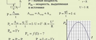
As we noted above, the microcontroller reads voltage and current values every 1 ms and accumulates 40 measurements of each parameter, which corresponds to two periods for a frequency of 50 Hz. The RMS values and power consumption are then calculated. The 1 ms period is generated using the built-in Timer A, operating in 16-bit mode with an overflow interrupt signal.
After receiving all samples, the effective (rms) values of voltage and current are calculated using the formula:
It should be noted that the resulting samples also contain the phase relationship between voltage and current. Thus, the AC active power, which is calculated by the formula (V×I×cosθ), can be obtained by calculating the average power using the following formula:
All calculated values are displayed on the LCD indicator screen. To work with the indicator, the lcd.h library for the CCS C compiler is used.
| Figure 6. | Measuring the power consumption of a soldering station using a digital wattmeter. |
| Figure 7. | Measuring the power consumption of a 2 kW water heater. |
Kinds
Initially, you need to measure the voltage, then the current, and then, based on the indicators, the power. Taking into account their purpose, the following types of wattmeters are distinguished:
- Power meter. Used to calculate the number of watts in the optical or radio range.
- Kilowatt meter. Used in the process of measuring large parameters (approximately 100 kV).
- Milliwatt meter. To measure small indicators (less than one).
- Varmeter. It shows the reactive power of an electrical circuit.
- Wattvarmeter. Makes it possible to find out information about active and reactive power in an AC electrical circuit.
You might be interested in this: Choosing a welding machine
Based on the type of measurement, conversion of indicators and obtaining information, the devices under consideration are divided into digital and household.
Digital
The basis for the functioning of a digital wattmeter is general measurements. For these purposes, the following is installed at the input: in series with the load - a current indicator, in parallel - a voltage indicator. They are made on the basis of thermistors, special transformers, thermocouples and others.
Instantaneous readings of the measured values will be transmitted to the integrated processor using a digital converter. Here the required measurements will be made and displayed as final data on the monitor and connected external devices.
Digital device
Domestic
The most popular and accurate household wattmeters are electrodynamic system devices.
The operating principle involves the interconnection of 2 coils. One is stationary and has a thick winding with a small number of turns. The other will be movable, the winding is made of thin wire. It has a large number of turns, so the resistance will be high.
It is connected in parallel to the load and is equipped with an auxiliary resistance (to prevent short circuits).
When the device is connected to the electrical network, electromagnetic fields are formed in them. During the interaction, a rotation is created that deflects the moving coil with the connected arrow to a specific angle.
Home appliance