AC electrical circuit with inductive element
In the electrical circuit of the inductor L
(Fig. 28, a), connected to a sinusoidal voltage source, a sinusoidal current arises
.
Sinusoidal current i
in the turns of a coil with inductance
L
, it excites a magnetic field;
this connection is characterized by flux linkage, which means that .
Here is the amplitude of the magnetic flux.
Thus, with a sinusoidal current in a section of the circuit with inductance L
, the magnetic flux Ф is also sinusoidal and is in phase with the current
i
.
The current and magnetic flux vectors are also in phase. , shown in the vector diagram (Fig. 28, b).
Electrical circuits of single-phase alternating current
Fig.5.4
Active resistance is greater than ohmic due to the phenomenon of surface effect. The surface effect is that the current is displaced from the central parts to the periphery of the conductor cross-section.
Inductive coil in a sinusoidal current circuit
First, consider an ideal inductive coil whose active resistance is zero. Let a sinusoidal current flow through an ideal coil with inductance L. This current creates an alternating magnetic field in the inductive coil, a change in which causes a self-inductive emf in the coil
(5.9)
This EMF is balanced by the voltage connected to the coil: u = eL = 0.
(5.10)
Thus, the current in the inductance is 90o out of phase with the voltage due to the phenomenon of self-induction. An equation of the form (6.10) for a real coil having active resistance R has the following form:
(5.11)
Analysis of expression (6.11) shows that the self-inductive emf interferes (resistance) with the flow of alternating current, due to which the current in a real inductive coil lags in phase with the voltage by a certain angle φ (0o< φ < 90o), the magnitude of which depends on the ratio R and L. Expression (6.11) in complex form has the form:
(5.12)
where ZL is the total complex resistance of the inductive coil; ZL—modulus of complex resistance; — initial phase of complex resistance; — inductive reactance (a fictitious value characterizing the response of an electrical circuit to an alternating magnetic field). Inductor impedance or complex impedance module
.
The complex equation (6.12) corresponds to a vector diagram (Fig. 5.5).
Rice. 6.5
From the analysis of the diagram it is clear that the voltage vector across the inductance is ahead of the current vector by 90o. In an alternating current circuit, the voltages in sections of the circuit are added not arithmetically, but geometrically. If we divide the sides of the voltage triangle by the current value Im, then we move on to a similar resistance triangle (Fig. 5.6).
From the resistance triangle we obtain several formulas: ; ; Rice. 5.6
;
; .
Capacitance in a sinusoidal current circuit
If a sinusoidal voltage is connected to a capacitor of capacitance C, then a sinusoidal current flows in the circuit
;
. (5.13)
From the analysis of expressions 5.13 it follows that the current is ahead of the voltage in phase by 90o.
Expression (5.13) in complex form has the form:
, (5.14)
where is capacitance, a fictitious calculated value that has the dimension of resistance.
If the complex resistance of inductance is positive, then the complex resistance of capacitance is negative
.
In Fig. Figure 6.7 shows a vector diagram of a circuit with a capacitance. The current vector leads the voltage vector by 90o.
Rice. 5.7
A real inductive coil and a capacitor connected in series in a sinusoidal current circuit
Coil with active resistance R
and inductance
L
and a capacitor with capacitance
C
are connected in series (Fig. 5.8). A sinusoidal current flows in the circuit
.
Let's determine the voltage at the input of the circuit. According to Kirchhoff's second law,
(5.15)
Let's substitute these formulas into equation (5.15). We get:
(5.16)
From expression (5.16) it is clear: the voltage in the active resistance is in phase with the current, the voltage on the inductance is ahead of the current in phase by 90o, the voltage on the capacitance is behind the phase of the current by 90o. Let's write equation 5.16) in complex form:
(5.17)
Rice. 5.8
Let's divide the left and right sides of equation (6.17) by √2. We obtain an equation for complexes of effective values of currents and voltages
, (5.18)
where is the complex resistance of the circuit; — module of complex resistance, or total resistance of the circuit; — the initial phase of complex resistance.
When constructing vector diagrams of a circuit, we consider three cases.
- XL > XC, the circuit is inductive. The voltage vectors on the inductance and capacitance are directed in opposite directions and partially compensate each other. The voltage vector at the input of the circuit leads the current vector (Fig. 5.9).
- Inductive reactance is less than capacitive reactance. The voltage vector at the circuit input lags behind the current vector. The circuit is capacitive in nature (Fig. 5.10).
- Inductive and capacitive reactances are the same. The voltages on the inductance and capacitance completely compensate each other. The current in the circuit is in phase with the input voltage. A resonant voltage mode occurs in the electrical circuit (Fig. 5.11).
The current in the resonant mode reaches a maximum, since the total resistance (z)
chain has a minimum value.
Condition for the occurrence of resonance: , hence the resonant frequency is equal to
.
From the formula it follows that the resonance mode can be achieved in the following ways:
- frequency change;
- change in inductance;
- change in capacity.
In resonant mode, the input voltage is equal to the voltage drop in the active resistance. Voltages can occur across the inductance and capacitance of the circuit that are many times greater than the voltage at the input of the circuit. This is explained by the fact that each voltage is equal to the product of the current I0 (and it is the largest) and the corresponding inductive or capacitive reactance (and they can be large).
.
Rice. 5.9 Fig. 5.10 Fig. 5.11
Parallel connected inductance, capacitance and active resistance in a sinusoidal current circuit
To the diagram in Fig. 5.12 sinusoidal voltage is connected. The circuit consists of inductance, capacitance and active resistance connected in parallel. Let's determine the current at the input of the circuit.
In accordance with Kirchhoff's first law: ,(6.19) where is active conductivity.
Fig.5.12
Let's substitute these formulas into equation (5.19). We get:
,(5.20)
where is inductive conductivity; — capacitive conductivity.
From equation (5.20) it is clear that the current in the branch with inductance lags in phase with the voltage by 90o, the current in the branch with active resistance is in phase with the voltage, the current in the branch with capacitance is ahead of the voltage in phase by 90o. Let us write equation (6.20) in complex form.
,(5.21)
where is complex conductivity; — total conductivity; — the initial phase of complex conduction.
Let us construct vector diagrams corresponding to the complex equation (5.21).
Rice. 5.13 Fig. 5.14 Fig. 5.15
In the diagram in Fig. 5.12, a current resonance mode may occur. Current resonance occurs when the inductive and capacitive conductivities are the same. In this case, inductive and capacitive currents directed in opposite directions completely compensate each other. The current in the unbranched part of the circuit is in phase with the voltage. From the condition for the occurrence of current resonance, we obtain the formula for the resonant frequency of the current
.
In current resonance mode, the total conductance of the circuit is minimal and the total resistance is maximum. The current in the unbranched part of the circuit in the resonant mode has a minimum value. In the idealized case R = 0,
And .
The current in the unbranched part of the circuit is I = 0. This circuit is called a filter - plug.
Resonant mode in a circuit consisting of a real inductive coil and a capacitor connected in parallel
Complex conductivity of the inductive branch
where is the active conductivity of the inductive coil; — total resistance of the inductive coil; — inductive conductivity of the coil; — capacitive conductivity of the second branch.
In the current resonance mode, the following equation is valid:
or
From this equation we obtain the formula for frequency resonance
(5.22)
Figure 5.16 shows a vector diagram of a circuit in resonant mode.
The current vector I2 leads the voltage vector by 90o. The current vector I1 lags behind the voltage vector by an angle φ,
Where .
Let us decompose the current vector I1 into two mutually perpendicular components, one of them, coinciding with the voltage vector, is called the active component of the current Iа1, the other is called the reactive component of the current Iр1.
Rice. 5.16
In the current resonance mode, the reactive component of the current Iр1 and the capacitive current I2, directed in opposite directions, completely compensate each other, the active component of the current Iа1 is in phase with the voltage (Fig. 5.17). The current I in the unbranched part of the circuit is in phase with the voltage.
Rice. 5.17
Power in a sinusoidal current circuit
Instantaneous power is the product of the instantaneous voltage at the input of the circuit and the instantaneous current. Let the instantaneous voltage and current be determined by the formulas:
Then
(5.23)
Average value of instantaneous power for the period
From the resistance triangle, a.
We get another formula:
.
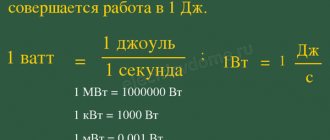
The arithmetic average value of power over a period is called active power and is designated by the letter P. This power is measured in watts and characterizes the irreversible conversion of electrical energy into another type of energy, for example, into thermal, light and mechanical energy. Let's take a reactive element (inductance or capacitance). Active power in this element, since the voltage and current in the inductance or capacitance differ in phase by 90o. There are no irreversible losses of electrical energy in reactive elements, and the elements do not heat up. A reversible process occurs in the form of an exchange of electrical energy between the source and the receiver. To qualitatively assess the intensity of energy exchange, the concept of reactive power Q is introduced. Let us transform expression (5.23):
where is the instantaneous power in the active resistance;
- instantaneous power in a reactive element (in inductance or capacitance). The maximum or peak value of power p2 is called reactive power
,
where x is reactance (inductive or capacitive). Reactive power, measured in reactive volt-amperes, is spent on creating a magnetic field in an inductance or an electric field in a capacitance. The energy stored in a capacitance or inductance is periodically returned to the power source. The amplitude value of the total power p = p1 + p2 is called the total power. The total power, measured in volt-amperes, is equal to the product of the effective values of voltage and current:
,
where z is the total resistance of the circuit. Total power characterizes the maximum capabilities of the energy source. Part of the total power can be used in an electrical circuit
,
where is the power factor or cosine phi.
Power factor is one of the most important characteristics of electrical devices. Special measures are taken to increase the power factor. Let's take a resistance triangle and multiply its sides by the square of the current in the circuit. We obtain a similar power triangle (Fig. 6.18).
From the power triangle we obtain a number of formulas:
, ,
Fig.5.18, . When analyzing electrical circuits using the symbolic method, the complex power expression is used, which is equal to the product of the complex voltage and the conjugate complex current. For a circuit that is inductive in nature (RL circuit)
,
where is the stress complex; — current complex; — conjugate current complex; - phase shift between voltage and current. , the current is the same as in an RL circuit, the voltage is ahead of the current in phase.
The real part of the total complex power is the active power. The imaginary part of complex power is reactive power. For a circuit that has a capacitive nature (R-C circuits), . The current is ahead of the voltage in phase.
.
Active power is always positive. Reactive power in an inductive circuit is positive, and in a capacitive circuit it is negative.
Power balance
For the circuit in Fig. 5.19, we write the equation according to Kirchhoff’s second law. Let's multiply the left and right sides of the equation by the conjugate current complex
where is the resulting reactance; I2 is the square of the current module.
where is the total complex, active and reactive power of the power source.
where are the active and reactive powers consumed by the circuit elements.
We get the equation
. (5.24)
Rice. 5.19
Two complex numbers are equal if their real and imaginary parts are individually equal, therefore equation (6.24) splits into two:
.(5.25)
The resulting equalities express the laws of conservation of active and reactive powers.
Coordinated operating mode of the electrical circuit. Matching the load with the source
In the diagram in Fig. 6.20 - total, active and reactive resistance of the EMF source, - total, active and reactive resistance of the load. Active power can only be released in the active resistances of the alternating current circuit. The active power released in the load is
.(5.26)
Active power developed by the generator
. Efficiency for this circuit:
.
Rice. 5.20
From formula (5.26) it is clear that the power released in the load will be maximum when the denominator is minimum. The latter occurs when , i.e. at . This means that the reactances of the source and load must be identical in magnitude and have a heterogeneous character. If the source reactance is inductive, the load reactance must be capacitive and vice versa.
.(5.27)
Let us establish the condition under which the greatest power will be transferred from the source to the load.
.
from here.
The greatest power is transferred from the source to the load when
. .(5.28)
Maximum power value
.
The mode of transfer of the greatest power from the source to the load is called the matched mode, and the selection of resistances according to equalities (6.28) is called matching the load with the source.
In a coordinated manner
.
Half the power is lost inside the source. Therefore, the matched mode is not used in power energy circuits. This mode is used in information circuits, where the power can be low, and the decisive factors are not considerations of the economy of signal transmission, but the maximum signal power in the load.
back to contents TOEE CHPP RiEKT Metrology Real physics Superconductivity
Did you know,
that in 1974 - 1980, Professor Stefan Marinov from Graz, Austria, carried out a series of experiments in which he showed that the Earth moves in relation to some cosmic reference frame at a speed of 360 ± 30 km/s, which clearly has some kind of absolute status. Naturally, he was not allowed to speak anywhere and he was forced to start publishing his scientific journal “Deutsche Physik”, where he explained the phenomenon he discovered. Read more in the FAQ on ethereal physics.
Inductive element in an AC circuit vector diagram
§ 54. Inductance in an alternating current circuit
The passage of electric current through a conductor or coil is accompanied by the appearance of a magnetic field. Let's consider an alternating current electrical circuit (Fig. 57, a), which includes an inductor with a small number of turns of wire of a relatively large cross-section, the active resistance of which can be considered almost equal to zero. Under the influence of e. d.s. generator, an alternating current flows in the circuit, exciting an alternating magnetic flux. This flow crosses the “own” turns of the coil and an electromotive force of self-induction arises in it
where L
— coil inductance;
is the rate of change of current in it. The electromotive force of self-induction, according to Lenz's rule, always counteracts the cause that causes it. Since e. d.s. self-induction always counteracts changes in alternating current caused by e. d.s. generator, it prevents the passage of alternating current. In calculations, this is taken into account by inductive reactance, which is designated XL
and measured in ohms.
Thus, the inductive reactance of the XL
, depends on the value of e.
d.s. self-induction, and therefore it, like e. d.s. self-induction, depends on the rate of change of current in the coil (on frequency ω) and on the inductance of the coil L
XL
= ω
L
, (58)
where XL
— inductive reactance,
ohm
;
ω - angular frequency of alternating current, rad/sec
;
L
is the inductance of the coil,
h
.
Since the angular frequency of alternating current ω = 2π f
, then the inductive reactance