Power in an alternating current circuit
Electrical appliances connected to the electrical network operate in an alternating current circuit, so we will consider power under these conditions. However, first, let's give a general definition of the concept.
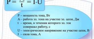
Power is a physical quantity that reflects the rate of conversion or transmission of electrical energy.
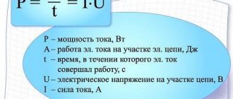
In a narrower sense, they say that electrical power is the ratio of the work performed over a certain period of time to this period of time.
If we rephrase this definition less scientifically, it turns out that power is a certain amount of energy that is consumed by the consumer over a certain period of time. The simplest example is an ordinary incandescent lamp. The rate at which a light bulb converts the electricity it consumes into heat and light is its power. Accordingly, the higher this indicator is initially for a light bulb, the more energy it will consume and the more light it will give off.
Since in this case there is not only a process of converting electricity into some other (light, heat, etc.), but also a process of oscillation of the electric and magnetic field, a phase shift appears between the current and voltage, and this should be taken into account in further calculations.
When calculating power in an alternating current circuit, it is customary to distinguish active, reactive and apparent components.
Concept of active power
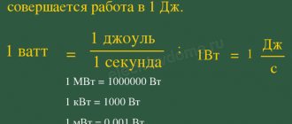
Active “useful” power is that part of the power that directly characterizes the process of converting electrical energy into some other energy. It is designated by the Latin letter P and measured in watts (W).
Active and reactive electrical power
The general dependence of electrical power on electric current and voltage has been known for a long time: this is the product. Let's multiply the current by the voltage - we get the value of this value consumed by the circuit from the network.
But in reality everything may not be so simple. Because by simply multiplying the voltage by the current, we get the total power value. It would seem that this is what you need! After all, we are usually interested in the full value of any quantity.
However, this relationship cannot be extended to electrical power, since the electricity and power on the basis of which the readings of our apartment meter change are not total, but active.
Active power
- this is the power that is consumed at the moment when there is both voltage and electric current synchronous with it at the same moment in the network. In fact, in DC circuits, with the exception of transient processes during on-off switching, this is what happens.
The voltage constantly “presses”; if the circuit is closed, a certain current constantly “presses”. As a result, the apparent and active power become equal, since current and voltage act in concert.
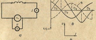
AC circuits are a different matter. The voltage in them changes its direction fifty times per second, and the current... sometimes lags behind, and sometimes leads the voltage. For example, if there is “inductance” in a circuit, that is, a coil of wire with many turns, then the current on such a circuit element will “lag” behind the voltage.
The reason is the back EMF of self-induction resisting the change in current in the coil. It turns out that the voltage has already been applied to the inductance, and the current cannot yet increase due to interference from the back-EMF.
Among students at many electrical engineering universities, there is the following artistic comparison: “It takes time for the current to run through each turn, but the voltage is there, already at the ends of the coil.”
The counter-induction emf causes a voltage drop and a decrease in current in the circuit. That is, the coil is a source of inductive reactance. But it differs from active resistance in that it does not generate any heat and does not consume any power at all in the usual sense.
There is simply an “empty” transfer of electricity from the source to the inductance. And the energy, redirected back and forth like a ball in table tennis, does not leave the network anywhere. This is reactive energy and the consumer at home does not have to pay the energy sales company for it.
Reactive Energy
, produced in the network per unit time, can be considered reactive power. It is calculated in the same way as the active one - by multiplying the reactive component of the current and the voltage.
The reactive component of the current is the one that does not coincide with the voltage in phase. The amount of “mismatch” is characterized by the phase shift angle. In the case of pure inductance, the phase shift is a maximum of 90°. This means that when the voltage reaches its highest value, the current is just beginning to rise.
And if there is a capacitor (capacitance) in the circuit, then the voltage, on the contrary, will lag behind the current by 90 degrees due to the fact that for a voltage drop to occur, the capacitor needs to charge its plates.
In the same way, the source and capacitor in the same circuit will exchange reactive energy, which will not be wasted on anything.
In a real circuit there is no purely active or purely reactive load, so the total power always consists of an active and reactive component, and the phase angle is between zero and 90°.
The reactive component of the current is equal to its product times the sine of the phase angle, and the active component is equal to the product times the cosine of this angle:
Q=I*sinφ; P=I*cosφ
The total power can be found using the Pythagorean theorem:
S=√(P^2+Q^2);
At the same time, reactive power, unlike active power, cannot be calculated in watts, because it is inefficient. Therefore, a special unit of measurement was invented for reactive power - reactive volt-amperes (VARs). And the total is measured in volt-amperes, without specifying the nature of the load.
Reactive power compensation
A huge number of inductive loads in the network in total have colossal reactive power, which returns to the generators and does not do any useful work, spending energy on heating cables and power line wires, overloading transformers, reducing their efficiency, thereby reducing the throughput of active currents.
If a capacitor is connected in parallel with an inductive load, the phase of the current in the source circuit will shift in the opposite direction, compensating for the angle created by the load inductance. With a certain ratio of ratings, it is possible to achieve the absence of phase shift, and therefore the absence of reactive currents in the power source circuit.
The capacitance of the capacitor is determined by the reactive (inductive) load resistance, which must be compensated: C =
1
/(2πƒX)
,
X = U²/Q
– load reactance,
Q
– load reactive power.
Compensation of reactive currents in the network can significantly reduce losses on the active resistance of power transmission line wires, cables and windings of power supply network transformers. In order to compensate for reactive power at production enterprises, where the main consumers of energy are asynchronous electric motors, induction furnaces, fluorescent lighting, which have inductive reactance, special capacitor units are often used that can manually or automatically maintain zero phase shift, thereby minimizing reactive losses .
On a power system scale, compensation occurs directly at power plants by monitoring the phase shift and providing the appropriate bias current to the rotor windings of the station’s synchronous generators.
Reactive power compensation is one of the components of a set of measures for Power Factor Correction (PFC) in the electrical network (Power Factor Correction - PFC in English literature). It is used to reduce electricity losses, both due to parasitic reactive and nonlinear components of current distortion in the power system. More detailed information about PFC (PFC) can be found on the page - power factor.
Online calculator for calculating reactive power and its compensation.
Just enter the values and click the mouse in the table.
| Reactive power Q = √((UI)²-P²) Reactance X = U²/Q Compensating capacitance C = 1/(2πƒX) |
Similar pages with calculations:
Calculate impedance.
Calculate the resonance frequency of the LC oscillating circuit.
Calculate the reactance of inductor L and capacitor C.
Alternative articles:
Diesel generator.
How to find active, reactive and apparent power
Active power refers to the energy that is irreversibly consumed by a source per unit of time for the consumer to perform some useful work. In the process of consumption, as already noted, it is converted into other types of energy.
In an alternating current circuit, the value of active power is defined as the average instantaneous power over a specified period of time. Consequently, the average value over this period will depend on the phase angle between current and voltage and will not be equal to zero, provided that active resistance is present in this section of the circuit. The last factor determines the name of active power. It is through active resistance that electricity is irreversibly converted into other types of energy.
When performing calculations of electrical circuits, the concept of reactive power is widely used. With its participation, processes such as the exchange of energy between sources and reactive elements of the circuit occur. This parameter will be numerically equal to the amplitude possessed by the variable component of the instantaneous power of the circuit.
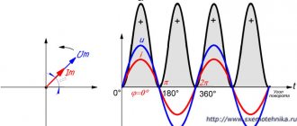
There is a certain dependence of reactive power on the sign of the angle φ shown in the figure. In this regard, it will have a positive or negative meaning. Unlike active power, which is measured in watts, reactive power is measured in var - reactive volt-amperes. The final value of reactive power in branched electrical circuits is the algebraic sum of the same powers for each element of the circuit, taking into account their individual characteristics.
The main component of total power is the maximum possible active power at a previously known current and voltage. In this case, cosф is equal to 1 when there is no phase shift between current and voltage. The total power also includes a reactive component, which is clearly seen from the formula presented above. The unit of measurement for this parameter is volt-ampere (VA).
Let the electricity receiver be connected to a source of sinusoidal voltage u(t) = Usin(ωt) and consume a sinusoidal current i(t) = I sin (ωt -φ), shifted in phase relative to the voltage by an angle φ. U and I are effective values. The value of instantaneous power at the receiver terminals is determined by the expression
| p(t) = u(t) ?i(t) = 2UI sin(ωt) sin (ωt -φ) = UI cos φ - UI cos (2ωt -φ) | (5.1) |
and is the sum of two quantities, one of which is constant in time, and the other pulsates with double frequency.
The average value p(t) over the period T is called active power and is completely determined by the first term of equation (5.1):
Active power characterizes the energy consumed irreversibly by the source per unit time to produce useful work by the consumer. The active energy consumed by electrical receivers is converted into other types of energy: mechanical, thermal, compressed air and gas energy, etc.
Formula for Full Power
S = UI
Apparent power = √ (Active power2 + Reactive power2)
kUA = √(kW2 + kUAR2)
It should be noted that:
- The resistor consumes active power and releases it in the form of heat and light.
- inductance consumes reactive power and releases it in the form of a magnetic field.
- The capacitor consumes reactive power and releases it in the form of an electric field.
All these quantities are trigonometrically related to each other, as shown in the figure:
Full power
Apparent power is all power, both active and inactive.
Apparent power is designated by the letter S and is measured in volt-amperes (VA).
The total power is equal to the square root of the sum of the squares of the active and inactive
power:
S = √(P² + N²)
In the case of a linear (uniform over a period) load, the total power is equal to the square root of the sum of the squares of the active and reactive
power. In this case, the inactive power consists entirely of the reactive component.
S = √(P² + Q²)
That is, the total power is obtained not by frontal addition of the active and inactive parts, but according to the law of a right triangle:
I hope I have clarified this issue a little.
If the topic is still unclear, read my new article, where I described the physics of the process more thoroughly.
Like _
, if you liked the article.
Write comments.
Share
also this article on social networks (the corresponding buttons next to the article are available) and, of course,
subscribe
to my channel! I look forward to your feedback! Good luck!
Active, reactive and apparent power formulas
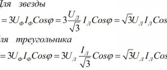
The main component is considered to be active power. It is a quantity characterizing the process of converting electrical energy into other types of energy. That is, in another way, it is the speed at which electricity is consumed. It is this value that is displayed on the electricity meter and paid by consumers. Active power is calculated using the formula : P = U x I x cosph.
Unlike active energy, which refers to the energy that is directly consumed by electrical appliances and converted into other types of energy - thermal, light, mechanical, etc., reactive power is a kind of invisible assistant. With its participation, electromagnetic fields are created that are consumed by electric motors. First of all, it determines the nature of the load, and can not only be generated, but also consumed. Reactive power calculations are made using the formula : Q = U x I x sinф.
Total power is a quantity consisting of active and reactive components. It provides consumers with the necessary amount of electricity and keeps them in working condition. For its calculations, the formula is used: S = .
Inactive power
Inactive power (passive power) is all power other than active, i.e. both reactive power and the power of any nonlinear distortions of the sinusoid, including the power of oscillations in oscillations (higher harmonics).
Inactive power is designated by the letter N and is measured in reactive volt-amperes (var).
Nonlinear distortion can be caused by a nonlinear load, such as switching power supplies without power factor correction.
