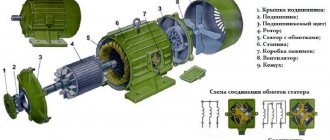
Location of three-phase motor contacts and winding continuity
We consider the placement of the ends of the windings of a three-phase motor
, we determine whether they are connected correctly.
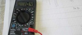
You can try to accurately calibrate the device and closely measure the resistance of all windings, comparing the results. But the difference in readings even in this case will not always be visible.
More accurate results can be obtained by the bridge method of measuring active resistance, but this is usually a laboratory method that is difficult for most electricians to access.
Measurement of current consumption in phases
When an interturn short circuit occurs, the ratio of currents in the windings changes, causing excess heating of the stator. A working motor has similar currents. Therefore, their direct measurement in an operating circuit under load more accurately reflects the real picture of the technical condition.
AC measurements
It is not always possible to find the total resistance of the winding taking into account the inductive component in a complete operating circuit. To do this, you will have to remove the cover from the terminal box and cut into the wiring.
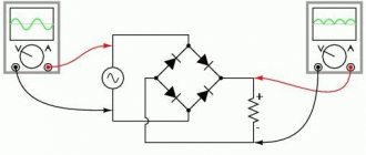
With the motor taken out of operation, you can use a step-down transformer with a voltmeter and an ammeter for measurement. The current can be limited by a current-limiting resistor or rheostat of the appropriate rating.
When taking measurements, the winding is located inside the magnetic core, and the rotor or stator can be removed. There will be no balance of electrical flows, for which the engine is designed. About how to check the engine and whether it can be checked with a multimeter? And as possible. Therefore, a reduced voltage is used and the current values are controlled, which should not exceed the nominal values.
Read also: How to solder wires without a soldering iron and rosin
The voltage drop measured across the winding, divided by the current, will give the impedance value according to Ohm's law. It remains to be compared with the features of other windings.
The same circuit allows you to determine the current-voltage properties of the windings. You just need to take measurements at various currents and write them down in tabular form or build graphs. If, when compared with similar windings, there are no serious deviations, then there is no interturn short circuit.
Ball in stator
The method is based on the development of a rotating electric field by serviceable windings. How to check an electric motor with a multimeter step by step. To do this, they are supplied with a three-phase symmetrical voltage, but certainly of a reduced value. For this purpose, three similar step-down transformers are usually used, operating in each phase of the power circuit.
To limit current loads on the windings, the experiment is carried out for a short period of time.
A small metal ball from a ball bearing is introduced into the rotating magnetic field of the stator immediately after turning on the voltage. If the windings are working properly, then the ball rolls synchronously along the inner surface of the magnetic circuit.
When one of the windings has an interturn short circuit, the ball will hang at the fault location.
During the test, the current in the windings must not exceed the rated value and it should be taken into account that the ball freely jumps out of the body at the speed of a slingshot.
Electrical check of winding polarity
Stator windings may not have markings for the start and end of the terminals and this will make correct assembly more difficult.
In practice, 2 methods are used to find polarity:
1. using a low-power source of constant current and a sensitive ammeter showing the direction of the current;
2. by using a step-down transformer and a voltmeter.
In both options, the stator is considered as a magnetic circuit with windings, operating similarly to a voltage transformer.
Checking polarity using a battery and an ammeter
On the outer surface of the stator, six wires lead out three separate windings, the beginnings and ends of which need to be found.
Using an ohmmeter, they call and mark the terminals related to each winding, for example, with the numbers 1, 2, 3. Then they randomly mark the beginning and end of any of the windings. An ammeter with an arrow in the center of the scale, capable of indicating the direction of the current, is connected to one of the remaining windings.
The minus batteries are aggressively connected to the end of the selected winding, and the plus batteries are briefly touched to its beginning and immediately break the circuit.
When a current pulse is applied to the first winding, it is transformed by electrical induction into a second circuit closed through an ammeter, repeating the original shape. In this case, if the polarity of the windings is guessed correctly, then the ammeter needle will deviate to the right when the pulse begins and move to the left when the circuit opens.
If the needle behaves differently, then the polarity is simply confused. All that remains is to mark the terminals of the 2nd winding.
Another 3rd winding is checked in a similar way.
Checking polarity using a step-down transformer and voltmeter
Here, too, first call the windings with an ohmmeter, determining the pins that relate to them.
Then the ends of the first selected winding are randomly marked for connection to a step-down voltage transformer, for example, 12 volts.
The two remaining windings are randomly twisted at one point with 2 leads, and the remaining pair is connected to a voltmeter and power is supplied to the transformer. Its output voltage is transformed into other windings with the same value, since they have an equal number of turns.
Due to the alternate connection of the 2nd and third windings, the voltage vectors will add up, and their sum will be shown by a voltmeter. How to check the parking sensor with a multimeter (tester). In our case, if the direction of the windings coincides, this value will be 24 volts, and if the polarities are different, it will be 0.
All that remains is to mark all the ends and perform a control freeze.
The article gives a general procedure for checking the technical condition of some random motor without certain technical features. They may change in each individual case. See them in the documentation for your equipment.
Currently, many household appliances are used, the operation of which is associated with an electric motor. Its malfunction causes anxiety and deprives it of its usual comfort. A multimeter is a universal measuring device that allows you to independently carry out initial diagnostics of the unit.
What you should know about the engine before checking it: 2 important points
Within the framework of the presented topic, it is enough to present the simplified operating principle and design features of any engine.
Operating principle: what electrical processes need to be well understood during repairs
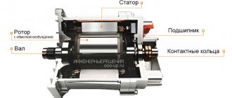
Any engine consists of a permanently fixed housing - a stator and a rotor rotating in it, which is also called an armature.
Its circular motion is created due to the influence of the rotating magnetic field of the stator on it, formed by the flow of electric currents through the stator windings.
When the windings are in good condition, rated currents flow through them, creating magnetic fluxes of optimal magnitude.
If the resistance of the wires or their insulation is broken, then leakage currents, short circuits and other damage are created that affect the operation of the electric motor.
The minimum possible gap is made between the stator and rotor. It can be violated:
- broken bearings;
- mechanical particles trapped inside;
- incorrect assembly and other reasons.
When rotating parts touch a stationary body, their destruction and additional mechanical loads are created. All this requires a thorough inspection, analysis of the condition of the internal parts before electrical checks begin.
Quite often, unqualified analysis is an additional cause of breakdowns. Use special tools and pullers to prevent damage to the shaft faces.
After disassembly, immediately during inspection they check for play, free movement of bearings, their cleanliness and lubrication, and correct seating.
In addition, the commutator motor may have severely worn plates or brushes.
All this must be checked before operating voltage is applied.
Design features affecting defect detection technology
Typically, the manufacturer indicates the electrical characteristics on a plate attached to the housing. This information is worth believing.
However, often during repair or rewinding the stator design changes, but the nameplate remains the same. This option should also be taken into account.
For a 220 volt household network the following motors can be used:
- commutator with brush mechanism;
- asynchronous single-phase;
- synchronous and asynchronous three-phase.
What tools are needed
First of all, you will need the device itself. But before you test the electric motor with a multimeter, you need to know the operating principles of this device.
The main functions of a standard meter allow you to measure with sufficient accuracy:
- the amount of active resistance of the circuit to electric current;
- constant pressure;
- AC voltage.
Some models additionally allow you to check:
- continuity of the electrical circuit;
- capacitance value of the capacitor.
To open the housings of equipment and motors, you need screwdrivers, wrenches, pliers, and a hammer. Thanks to this set, as well as minimal knowledge in electrical engineering, the question of how to check an electric motor with a multimeter makes it easy to identify faults that can be corrected independently.
Complex damage is eliminated by service workshops that have precision equipment.
Which electric motors can be tested with a multimeter?
Electric machines use the principle of rotation of a moving part relative to a static one due to magnetic induction that occurs in coils through which electric current flows. Depending on the type of food, they are divided into the following:
| Structural element | Supply current | |
| Variable | Constant | |
| Fixed | Stator | Inductor |
| Mobile | Rotor | Anchor |
Electric motors are powered by current:
- Constant, with circuit solutions to simplify the adjustment of power and speed.
- AC, single or three phase. They are divided:
- synchronous, in which the rotor speed coincides with the frequency of change of the stator induction;
- asynchronous. The number of revolutions does not depend on the network. The rotors of such motors differ in the winding connection diagram; they can be:
- short-circuited, where the role of windings is performed by aluminum or copper rods, cast into the surface at an angle to the axis of rotation, connected at the ends of the rotor by rings;
- phase: the ends of the coil laid in the grooves of the core are connected by a “star” or “triangle” with contact lamellas on the rotor shaft.
The phase rotor is more complex, its starting characteristics are better, and the adjustments are wider. But more often they use a squirrel-cage rotor due to its simplicity of design, high reliability, and lower price.
What faults in an electric motor can a multimeter detect?
Quite often, a multimeter, a multifunctional electronic measuring instrument, is used to test AC motors. It is available to almost every home craftsman and allows you to identify some types of faults in electrical appliances, including electric motors.
The most common malfunctions that occur in electrical machines of this type are:
- winding breakage (rotor or stator);
- short circuit;
- interturn closure.
Let's look at each of these problems in more detail and look at methods for identifying such faults.
Checking for breakage or integrity of the winding
Winding breakage is a fairly common occurrence when improper operation of an electric motor is detected. A break in the winding can occur in both the stator and the rotor.
If one phase in a winding connected according to a star circuit is broken, then there will be no current in it, and in other phases the current values will be overestimated, and the engine will not work. There may also be a break in the parallel phase branch, which will lead to overheating of the serviceable phase branch.
If one phase of the winding (between two conductors) connected in a delta circuit was broken, then the current in the other two conductors will be significantly less than in the third conductor.
If a break occurs in the rotor winding, current fluctuations will occur with a frequency equal to the frequency of slip and voltage fluctuations, while a hum will appear and the engine speed will be reduced, and vibration will also occur.
These reasons indicate a malfunction, but the malfunction itself can be identified by checking and measuring the resistance of each motor winding.
Checking the electric motor by external inspection
Before checking the motor winding with a multimeter, you need to examine the disconnected motor along with the power cord to look for mechanical damage, signs of insulation breakdown or overheating. The motor axis should rotate easily in the bearings, without jamming or jamming. There should be no smell of burnt insulation, oil spreading, or sagging.
Read also: How to drill out a broken bolt
The absence of visible damage may require disassembling the engine to inspect graphite brushes, contact lamellas, the condition of the coils, and their leads. The shorting of the electrical circuit causes heating, which is manifested in clearly visible color changes near the breakdown of the insulation.
How to find an open or interturn short circuit
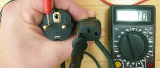
If no signs of damage are visible, then it’s time to start measuring with a digital tester. To do this you need to do the following:
- Insert the test leads into the sockets on the front panel.
- Use the mode switch to select continuity, connect the bare ends of the probes, the meter will beep. Rupture will stop the sound. This checks the presence and serviceability of the battery, measuring cords, and sockets. This mode allows you to ring the circuit without looking at the indicator, by ear.
- If the device does not have a beeper, the resistance measurement mode is activated at the lowest limit, usually “200” Ohms. The alignment of the cord tips will be reflected on the multimeter indicator with numbers indicating the resistance of the probe wire within 0.6 ÷ 1.5 Ohms.
A break is looked for by testing or measuring the resistance of wires, cords, all coils, after first disassembling the connection of their ends. The rotor is checked by measuring each pair of leads.
The interturn short circuit of windings made of relatively thick wire with low resistance cannot be determined with a multimeter. Shorting a few turns will reduce the total resistance by fractions of an ohm that are not reflected by the display.
How to check the stator winding of an angle grinder at home in different ways
There are a large number of different electrical devices that can be used to diagnose the stator. However, at home, a limited number of technical means are used. Some are presented in the following videos.
Checking the armature/rotor and stator with a multimeter/tester
, a multimeter, or more commonly called a tester, is used as a tool for diagnosing the rotor and stator of an electric drive . Used to measure various electrical parameters : resistance, current, voltage. To determine faults in the form of broken wires or breakdown of the winding on the housing, the “ohmmeter” mode is used, that is, a certain resistance value is set, which is comparable to that present in the circuit being tested. In this case, with a limit of 200 Ohms.
A breakdown of the stator to the housing is determined by applying indicator probes to its housing and one of the ends of the winding. The presence of any resistance value on the indicator indicates the presence of a defect in the form of a breakdown of the winding to the housing. When diagnosing a winding break, the device indicator will not show anything when the probes are aligned with the winding terminals.
More complex manipulations should be carried out when checking the rotor windings of an electric drive. A winding break can occur in any connection with a single commutator lamella. Therefore, it is necessary to check the resistance between all lamellas of the collector , applying indicator probes to them one by one. In the absence of a break, the resistance will have the same small value in all cases. Any deviations indicate the presence of a break. Breakdown of the winding to the housing is checked with probes when they come into contact with the commutator and the “iron” from a set of electrical steel sheets. The indicator scale should not react to this action.
However, it is impossible to determine the turn-to-turn short circuit with a multimeter. A device called a short-circuited turn indicator (SCI) is used here. More details about it in the information below.
For interturn short circuit, indicator
The operating principle of the device for determining interturn short circuits is shown in the following video. The device in the winding being tested induces a magnetic field . If there are short-circuited turns in the winding, the short circuit current causes increased resistance to the electromagnetic field generated by the device. By adjusting the IKZ, a setting is made, upon reaching which a light signal is triggered (the indicator light changes color from green to red) or a sound is heard . In addition to the main application, the author shows a method for determining where the winding wires are connected to the commutator lamellas, in the absence of visually visible contacts.
Makita, without instruments
smoke began to appear during operation , which is a sure sign of a burnt out rotor or stator. To determine the reasons, the author performed a complete disassembly of the angle grinder , which made it possible to perform a good external inspection of the components of the angle grinder suspected of malfunctioning. While no signs of smoke damage were found on the rotor, several places of burnt electrical insulating varnish were clearly visible on the stator.
Important: after a visual inspection, it is necessary to once again check with instruments the unit on which no external defects were found. So, for example, in this case, a multimeter detected breaks in the winding on the rotor. By the way, an external inspection of the stator was sufficient, since the multimeter could not detect a defect in the form of an interturn short circuit.
Automatic multimeter: performs measurements quickly and efficiently
The multimeter, which is presented in the following video, is easy to use and allows you to take readings without unnecessary fuss, when the measured values “jump” in a device that does not have this option. A method for determining the measurement error associated with the resistance of indicator probes is shown. The approximate value of the winding resistance where there are no faults is given.
Sections: Do-it-yourself repair of grinders, Stators
Previous article: Soft start of an angle grinder Next article: Dimensions of disks for an angle grinder
Checking the insulation of the windings relative to the housing
Using a multimeter in maximum resistance measurement mode, you can make sure that there is no poor insulation or short to ground. This is life-threatening.
Everything is checked with the motor disconnected from the mains. One probe of the device is connected to the body, the second touches all the terminals of the windings. The indicator should show a break, or a large, hundreds of megaohms, resistance in all cases.
Then you need to check that there is no breakdown of the insulation between the windings, for which the probes are connected in pairs to the terminals of different coils. The indicator should not show resistance.
Collector design
Collector models have also become very widespread. Their design features differ significantly when compared with asynchronous models. Checking the functionality when using a multimeter is carried out as follows:
- The tester is set to detect Ohm. The test begins with measuring the resistance on the collector lamellas. It is worth considering that normally the data obtained should not differ significantly.
- Next, the resistance indicator is measured, for which one probe of the device is applied to the armature body, the other to the commutator. The resulting resistance value should be high, approaching infinity. This indicates that the insulation is in good condition.
- The next step involves determining the stator for winding integrity. To do this, one probe is applied to the stator housing, and the other to the terminals. The higher the score, the better.
When using a multimeter, it will not be possible to check the turn-to-turn short circuit. A special apparatus is used for this.
Checking asynchronous three-phase motors with squirrel-cage rotor
A three-phase motor can be checked quickly with a multimeter. Having disassembled the ends, measure the resistance of each of them with a multimeter. The difference in values should be less than 10%. Along the way, you need to make sure that there is no breakdown on the housing between the coils.
The exact location of the interturn short circuit will be shown by a device made from a step-down three-phase transformer; the stator of the disassembled motor is connected to the terminals. Power is supplied, a metal ball is placed inside, which, if the windings are in good condition, rolls along the inner surface. If there is a short circuit in the turns, the ball will stick in this place. Repairers use current clamps. Each phase coil of the same resistance passes equal current if there is no phase voltage imbalance. If there is more current in one, most likely there is an interturn fault.
Transformer interturn short circuit
Transformers have a common malfunction - the short circuit of the turns among themselves. It is not always possible to detect this defect with a multimeter. It is necessary to carefully inspect the transformer. The winding wire has varnish insulation; when it breaks down, there is a resistance between the turns of the winding that is not zero. This leads to heating of the winding.
When inspecting the transformer, there should be no burning, charred paper, swelling of the fill, or blackening. If you know the type and brand of the transformer, you can find out what the winding resistance should be. The multimeter is switched to resistance mode. Compare the measured resistance with reference data. If the difference is more than 50%, then the windings are faulty. If the resistance data could not be found in the reference book, then you probably know the number of turns, the type and cross-section of the wire, and you can calculate the resistance using the formulas.
To check the transformer of the power supply with a low voltage output, we connect a voltage of 220 V to the primary winding. If smoke or smell appears, then immediately turn it off, the winding is faulty. If there are no such signs, then we measure the voltage with a tester on the secondary winding. If the voltage is reduced by 20%, there is a risk of failure of the secondary winding.
If there is a second serviceable transformer, then by comparing the resistances the serviceability of the windings is determined. To check in more detail, use an oscilloscope and a generator.
Checking capacitor motors
An asynchronous motor, where a capacitor is connected in series with one of the coils to create a phase shift of the current, is a capacitor motor. The test of such an electric motor, in addition to continuity testing, includes checking the capacitance, which is selected to create a phase shift between the coils equal to 90 degrees, so that the rotor torque is maximum.
The capacity of the working capacitor is relatively small; it can be checked if the multimeter can measure the capacitance by connecting it to the terminals of a part disconnected from the motor circuit, after briefly short-circuiting its terminals.
Checking an asynchronous three-phase motor
The most widely used are asynchronous motors, which are designed for two or three phrases.
The three-phase motor has high performance. There are two main problems with this design:
- Contact occurs in the wrong place.
- No contact.
The design consists of three coils that are connected in the shape of a star or triangle. To do the check correctly, it should be taken into account that the performance of the motor is determined by several factors:
- Insulation quality.
- Reliability of all contacts.
- Correct winding.
Resistance is defined as follows:
- A short to frame is usually checked using a megger. If this tool is not available, you can use a tester; the maximum ohmic value is set. If you use a tester, you should not expect the indicator to be accurate.
- It is worth considering that before using the measuring device, you should disconnect the electric motor from the network. Otherwise it will burn.
- Before using the measuring device, the device must be calibrated. To do this, you need to set the arrow to zero with the probes in the closed position.
- One probe is applied to the body. This is done in order to check the presence of contact. After this, the indicator is checked, for which the second probe must also touch the body. If the indicator is normal, each phase is checked in turn.
After checking the quality of the insulation, you should make sure that all three windings are intact. To do this, you can call them. If a break is detected, it should be corrected and then further checked.
Checking wound rotor motors
Testing a motor with a wound rotor is similar to testing a conventional asynchronous motor; in addition, the rotor windings are measured. Their connection diagram is made as a “star” for a three-phase supply network with a voltage of 380 volts, or for a network of 220 volts a “triangle” is used.
Measurements with a multimeter are carried out using the same method as for the stator.
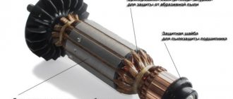
How to check an electric motor armature: 4 types of different designs
The rotor windings create a magnetic field, which is influenced by the stator field. They must also be in good working order. Otherwise, the energy of the rotating magnetic field will be wasted.
Armature windings have different designs for wound-rotor, asynchronous and commutator motors. This is worth considering.
Synchronous wound rotor models
At the anchor, wire leads are created in the form of metal rings located on one side of the shaft near the rolling bearing.
The wires of the circuit are already assembled to these rings, which causes small differences in checking them with a multimeter. You should not turn them off, however, the technique described above for the stator is, in principle, suitable for this design.
Read also: Average car mileage per year in Russia
Such a rotor can also be conditionally represented as a working transformer. All you need to do is compare the individual resistances of their circuits and the quality of insulation between them, as well as the housing.
Asynchronous motor armature
In most cases, the situation here is much simpler, although there may be problems. The fact is that such a rotor is made in the shape of a “squirrel wheel” and is difficult to damage: a fairly reliable design.
The short-circuited windings are made of thick aluminum rods (rarely copper) and are firmly pressed into the same bushings. All this is designed for the flow of short circuit currents.
However, in practice, various damages occur even in reliable devices, and somehow they need to be found and eliminated.
A digital multimeter is not required to identify faults in the squirrel wheel winding. Here you need other equipment that supplies voltage to the short circuit of this armature and controls the magnetic field around it.
However, internal failures of such structures are usually accompanied by cracks on the body, and they can be noticed during a careful internal inspection.
Who is interested in such testing using electrical methods, watch the video of the owner Viktor Yungblyudt. He shows in detail how to determine the breakage of the rods of such a rotor, which makes it possible to subsequently restore the functionality of the entire structure.
Commutator motors: 3 winding analysis methods
The electrical circuit diagram of a commutator motor in a simplified form can be represented by rotor and stator windings connected through a brush mechanism.
The diagram of an assembled electric motor with a commutator mechanism and brushes is shown in the following picture.
The rotor winding consists of parts connected in series with each other by a certain number of turns on the collector plates. They are all of the same design and therefore have equal active resistance.
This allows you to check their serviceability with a multimeter in ohmmeter mode using three different methods.
The simplest measurement method
I show principle No. 1 of determining the resistance between the collector plates in the photo below.
Here I made one simplification that cannot be made in a real test: I was too lazy to remove the brushes from the brush holder, and they create additional chains that can distort the information. Always take them out for accurate measurements.
The probes are placed on adjacent lamellas. This type of measurement requires precision and perseverance. You must mark the collector with paint or a felt-tip pen. From there you will have to move in a circle, taking sequential measurements between all successive plates.
Constantly monitor the device readings. They should all be the same. However, the resistance of such sections is small and if the ohmmeter does not respond to it accurately enough, then it can be sensed by increasing the length of the chain being measured.
Method No. 2: diametric measurement
This second method will require even greater care and concentration. The ohmmeter probes must be placed not on the nearest adjacent plates, but on diametrically opposite ones.
In other words, the multimeter probes should fall on those plates that are connected by brushes when the electric motor is running. And to do this, they will need to be marked somehow so as not to get confused.
However, even in this case there may be difficulties associated with measurement accuracy. Then you will have to use the third method.
Method No. 3: indirect method of comparing small resistance values
To measure, we need to assemble a circuit that includes:
- 12 volt battery;
- powerful resistance of about 20 Ohms;
- multimeter with ends and connecting wires.
It should be imagined that the measurement accuracy increases the stability of the created current source due to:
- high battery capacity, providing the same voltage level during operation;
- increased power of the resistor, eliminating its heating and deviation of parameters at currents up to one ampere;
- short and thick connecting wires.
One connecting wire is connected directly to the battery terminal and the collector lamella, and a current-limiting resistor is inserted into the second, eliminating large currents. A voltmeter is placed parallel to the contact plates.
The next pairs of lamellas on the collector are sequentially moved with probes and readings are taken with a voltmeter.
Since the battery and resistor produce the same voltage for a short time of each measurement, the voltmeter readings will depend only on the resistance value of the chain connected to its terminals.
Therefore, with equal readings, we can conclude that there are no defects in the electrical circuit.
If desired, you can measure the current through the lamellas with a milliammeter and, using Ohm's law, use an online calculator to calculate the value of active resistance.
My digital Mestek MT102, despite the shortcomings identified in it, copes well with this task.
DC motors
The design of their rotor is reminiscent of the armature device of a commutator motor, and the stator windings are created to work with a switching circuit with parallel, series or mixed excitation.
The stator and armature testing methods disclosed above allow you to check a DC motor, both asynchronous and commutator.
Checking the starting capacitor
A reliable start of the electric motor occurs when, at the moment the power is turned on, a starting capacitor is briefly connected in parallel with the working capacitor. It serves to create a circular magnetic field at the start; after the rotor begins to rotate, it turns off. The starting capacitor can be easily checked with a multimeter, even if it does not have a capacitance measurement mode:
- The capacitor, having previously been discharged by shorting the terminals, is disconnected from the electric motor circuit and carefully inspected. If there are cracks, swelling of the body, or other visible damage, the container can be replaced with a new one without checking.
- Set the resistance measurement mode on the tester to a limit of 2000 kilo-ohms, check the functionality by briefly connecting the measuring probes.
- Connect the probes to the terminals of the capacitor. When discharged, it will begin to quickly charge from the probes of the device. Its capacity is relatively large, much larger than that of the working capacitor. The multimeter indicator will initially show a small resistance, which will increase as the capacity is charged, because the charging current gradually decreases. At the end of the process, the multimeter will show an infinitely high resistance, a break.
- Reverse the polarity of connecting the probes to the capacitor, see the resistance increase, with a break indication at the end of the measurement. This will confirm that the capacitor is working.
- Check the breakdown of the plates on the capacitor body, if it is metal, by measuring the resistance between the part body and each of the terminals in turn.
The tester indicator should show a break. Other values are a sign of a malfunction.
How to check the motor winding on the stator: general recommendations
The three-phase stator has three built-in windings. There are six wires coming out of it. In some designs you can find 3 or 4 terminals, when the triangle or star connection is assembled inside the housing. But this is rarely done.
Testing them with a multimeter in ohmmeter mode allows you to determine whether the ends are connected to the windings. You just need to place one probe on an arbitrary pin, and use the other one to alternately measure the active resistance on all the others.
The pair of wires on which resistance in Ohms is detected will belong to the same winding. They should be visually separated and marked, for example, with the number 1. Do the same with other wires.
Here we must clearly understand that, according to Ohm’s law, the current in the winding is created under the influence of the applied voltage, which is counteracted by the total resistance, and not by the active one measured by us.
We take into account that the windings are wound from the same wire with the same number of turns, creating equal inductive reactance. If the wire is short-circuited or torn during operation, its active component, as well as its full value, will be disrupted.
The interturn short circuit also affects the value of the active component.
Therefore, measurements of the active resistance of the windings and their comparison make it possible to reliably judge the serviceability of the stator circuits and conclude that their integrity is not compromised.
Single-phase asynchronous motor: features of stator windings
Such models are created with two windings: working and starting, like, for example, a washing machine. In the vast majority of cases, the active resistance of the working chain is always less.
Therefore, when only three ends are removed from the stator, this means that the resistance must be measured between all of them. The results of three measurements will show:
- the smaller value is the working winding;
- middle - starting;
- large - serial connection of the first two.
How to find the beginning and end of each winding
The method only allows you to identify the general winding direction of each wire. But for practical operation of the electric motor this is more than enough.
The stator is considered as an ordinary transformer, which in principle is what it actually is: the same processes occur in it.
To operate, you will need a small constant voltage source (a regular battery) and a sensitive voltmeter. Better than a pointer. It displays information more clearly. It is difficult to monitor the change in sign of a rapidly changing pulse on a digital multimeter.
A voltmeter is connected to one winding, and voltage from the battery is briefly applied to the other winding and immediately removed. The deviation of the arrow is assessed.
If, when applying a “plus” to the first winding, an electromagnetic pulse was transformed into the second, deflecting the arrow to the right, and when it is turned off, it moves to the left, then it is concluded that the wires have the same direction when the “+” of the device and the source coincide.
Otherwise, you need to switch the voltmeter or battery - that is, change the ends of one of the windings. The next third chain is checked in the same way.
And then I simply took my working asynchronous engine with a multimeter and showed with photographs the method for evaluating it.
Personal experience: checking the stator windings of an asynchronous electric motor
For this article I used my new Mestek MT102 pocket multimeter. At the same time, I continue to identify the shortcomings of its design, which I already showed in the article earlier.
Electrical tests were carried out on a three-phase motor connected to a single-phase network through capacitors in a star configuration.
General assessment of the winding insulation condition
Since all the windings are already assembled together at the terminal terminals, I started taking measurements by checking their insulation resistance relative to the housing. One probe is located on the terminal block of the zero assembly, and the second is on the socket of the cover fastening screw. My Mestek showed no leaks.
I didn't expect any other result. This method of measuring the insulation condition is very inaccurate and it simply cannot detect most damage: 3 volt battery power is clearly not enough.
But it’s still better to do at least this way than to completely neglect such a check.
To fully analyze the dielectric layer of conductors, it is necessary to use the high voltage that megohmmeters produce. Its value usually starts from 500 volts and above. The home master does not have such devices.
You can do it indirectly, using a household network. To do this, a voltage of 220 volts is supplied to the winding and housing terminals through an incandescent test lamp with a power of about 75 watts (a current-limiting resistance that excludes the supply of phase potential to the circuit) and a series-connected ammeter.
The expected leakage current through normal insulation will not exceed microamps or their fractions, but you need to count on emergency mode and start measuring within amperes. By measuring the current and voltage, the insulation resistance is calculated.
However, such work is performed under current voltage . She's dangerous. It can only be performed by those workers who have good practical skills as an electrician and have at least a third safety group.
When using this method, keep in mind that:
- a full-fledged phase is supplied to the motor body: it must be located on a dielectric base and have no contact with other objects;
- even a temporarily assembled circuit requires reliable insulation of all ends and wires, strong fastening of all clamps;
- The lamp bulb may break: it must be kept in a protective case.
Measurement of winding resistance
Here you need to disassemble the wiring diagram and remove all jumpers. I switch the multimeter to ohmmeter mode and determine the active resistance of each winding.
The device showed 80, 92 and 88 Ohms. In principle, there is no big difference, and I explain deviations of several ohms by the fact that the crocodile does not provide high-quality electrical contact. Different transition resistance is created.
This is one of the disadvantages of this multimeter. The probe does not fit well into the crocodile groove, and besides, the thin metal of the clamp moves apart. I immediately had to tighten it with pliers.
Measuring insulation resistance between windings
I show this principle because it must be followed between each winding. However, instead of an ohmmeter, you need a megohmmeter or, as a last resort, check with household voltage according to the method I described above.
A multimeter can be misleading: it will show good insulation where hidden defects will be created.
Repair of asynchronous motors
Any damage found must be repaired. Some of them can be easily done at home, “on your knee”; checking an electric motor with a 220 volt multimeter is quite simple. Others will require contacting an electrical repair shop, where they can repair both mechanical damage and replace or rewind the coils.
You cannot begin complex repairs without conditions, a base of experience and knowledge.
Winding insulation test
The operational reliability of the electric motor is determined by the state of the insulation. Vibration of a running engine, thermal and chemical processes worsen the electrical insulating properties. Therefore, when diagnosing after repair, you need to test the insulation in an electrical laboratory.
There is a test transformer, the secondary increased voltage of which is supplied between one of the windings and the remaining coils connected to the motor housing. Test voltage values:
| Electric motor power, kW | Test voltage, V |
| Up to 1 | 500+2Unominal |
| From 1, for a nominal voltage of 100 volts | 1000+2Un, but not less than 1.5 kV |
If the repair was carried out with your own hands and cannot be checked with a stand, you need to test the motor insulation with a megger. It supplies high voltage, which is not found in a multimeter.
When checking an electric motor with a 380-volt multimeter, you need to take into account that the work is carried out with the mains disconnected. Working with electricity requires composure and attention so as not to receive an electric shock. By following safety precautions, checking the serviceability of the unit is quite simple.
Non-standard check
The most accurate way is to check the stator using a metal ball and a step-down current transformer. The stator is connected to the terminals of the three phases from the transformer. After checking that the connection is correct, we turn on our reduced-voltage circuit to the network.
We throw a ball inside the stator and observe its behavior. If it “sticks” to one of the windings, this means that an interturn short circuit has occurred on it. The ball is spinning in a circle - the stator is working. A rather unscientific, but effective method for detecting an interturn short circuit on the stator.