Design of a synchronous electric motor with an excitation winding
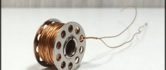
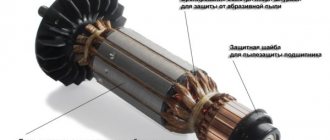
A synchronous electric motor with an excitation winding, like any rotating electric motor, consists of a rotor and a stator. The stator is the stationary part, the rotor is the rotating part. The stator usually has a standard three-phase winding, and the rotor is made with an excitation winding. The excitation winding is connected to slip rings to which power is supplied through brushes.
Synchronous motor with field winding (brushes not shown)
Independently excited motor
An independently excited DC motor implements the third principle of speed control. Its difference is that the field winding and the magnetic field of the main poles are connected to different sources. The excitation current is a constant characteristic, but the magnetic field changes. In this case, the number of shaft revolutions at idle changes, the rigidity of the characteristic remains the same.
Thus, the operating principle of a dct with independent excitation is quite complex due to the independent operation of two sources, however, its main advantage is greater efficiency.
Principle of operation
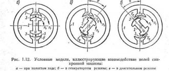
The constant speed of rotation of a synchronous electric motor is achieved through the interaction between a constant and rotating magnetic field. The rotor of a synchronous electric motor creates a constant magnetic field, and the stator creates a rotating magnetic field.
The operation of a synchronous electric motor is based on the interaction of the rotating magnetic field of the stator and the constant magnetic field of the rotor
Stator: rotating magnetic field
Three-phase alternating voltage is supplied to the windings of the stator coils. As a result, a rotating magnetic field is created, which rotates at a speed proportional to the frequency of the supply voltage. You can read more about how a rotating magnetic field is formed using a three-phase supply voltage in the article “Three-phase asynchronous electric motor”.
Interaction between rotating (at the stator) and constant (at the rotor) magnetic fields
Rotor: constant magnetic field
The rotor winding is excited by a direct current source through slip rings. The magnetic field created around the rotor, excited by direct current, is shown below. Obviously, the rotor behaves like a permanent magnet, since it has the same magnetic field (alternatively, one can imagine that the rotor is made of permanent magnets). Let's consider the interaction of the rotor and the rotating magnetic field. Suppose you give the rotor an initial rotation in the same direction as the rotating magnetic field. The opposite poles of the rotating magnetic field and the rotor will be attracted to each other and they will stick together using magnetic forces. This means that the rotor will rotate at the same speed as the rotating magnetic field, that is, the rotor will rotate at a synchronous speed.
Magnetic fields of the rotor and stator linked to each other
Execution options
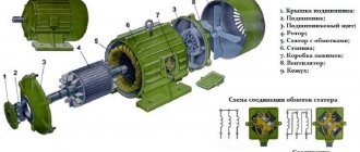
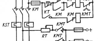
1 – gear; 2 – coupling; 3 – lever; 4, 9 – covers; 5 – relay; 6 – collector; 7 – brushes; 8 – bushing; 10 – bolt; 11 – body; 12 – pole; 13 – anchor; 14 – ring; 15, 16 – clips; 17 – plunger; 18 – roller
In the steel housing 11 of the starter (diagram 1) four poles 12 with field windings are fixed, three of which are connected to the armature winding 13 in series and one in parallel.
The starter armature shaft rotates in two bushings 8 made of sintered materials impregnated with oil. The bushing of the rear end of the shaft is pressed into cover 9, and the bushing of the front end of the shaft is pressed into the clutch housing. At the front end of the armature shaft there is a starter drive, which includes freewheel 2 and drive gear 1, which move along the shaft splines when the starter is turned on. The starter covers are cast from aluminum alloy.
A traction relay 5 is attached to the front cover 4, connected through a plastic lever 3 and a ring 14 to the starter drive. The relay ensures that the gear engages with the flywheel ring and connects the electrical circuit of the starter windings to the battery when starting the engine.
On the back cover 9 there are brush holders with four copper-graphite brushes 7. The brushes are pressed by springs to the end commutator 6 of the armature. The end collector is made in the form of a plastic disk in which copper contact plates are filled. Such a commutator reduces the length of the starter, reduces its weight and contributes to more stable and long-lasting operation of the brush contacts. The covers and the starter housing are tightened together with two bolts 10.
Freewheel 2 consists of outer 16 and inner 15 races. The inner race is integrated with the starter drive gear. The outer race is combined with a hub, which is connected to the armature shaft through spiral splines. Spiral splines ensure rotation of the coupling as it moves along the shaft, which makes it easier to engage the teeth of gear 1 of the starter and the flywheel ring.
In the outer cage there are three grooves of variable width, in which rollers 18 and pressing plungers 17 with springs are placed. The rollers are constantly pressed into the narrowed part of the cutouts, wedging the outer and inner races. When starting the engine, the jamming of the races intensifies, and after starting, the races become wedged, since the rollers, overcoming the resistance of the springs of the pressure plungers, roll out into the expanded part of the grooves of the outer race of the coupling.
Source
Direct starting of a synchronous motor from the electrical network
Why are synchronous electric motors not started from the electrical network?
If the rotor has no initial rotation, the situation is different from that described above. The north pole of the rotor's magnetic field will be attracted to the south pole of the rotating magnetic field, and will begin to move in the same direction. But since the rotor has a certain moment of inertia, its starting speed will be very low. During this time, the south pole of the rotating magnetic field will be replaced by the north pole. This will create repulsive forces. As a result, the rotor will begin to rotate in the opposite direction. Thus the rotor will not be able to start.
Damper winding - direct start of a synchronous motor from the electrical network
To realize self-starting of a synchronous electric motor without a control system, a “squirrel cage” is placed between the rotor tips, which is also called a damper winding. When the electric motor starts, the rotor coils are not excited. Under the influence of a rotating magnetic field, a current is induced in the turns of the “squirrel cage” and the rotor begins to rotate in the same way as induction motors are started.
When the rotor reaches its maximum speed, power is applied to the rotor field winding. As a result, as mentioned earlier, the poles of the rotor mesh with the poles of the rotating magnetic field and the rotor begins to rotate at a synchronous speed. When the rotor rotates at synchronous speed, the relative motion between the squirrel cage and the rotating magnetic field is zero. This means that there is no current in the short-circuited turns, and therefore the “squirrel cage” does not affect the synchronous operation of the electric motor.
Parallel motors
Engine diagram.
The parallel excitation motor circuit is shown in Fig. 1.25. The armature winding and field winding are connected in parallel. In this circuit: I is the current consumed by the motor from the network, Iа is the armature current, Iв is the excitation current. From Kirchhoff's first law it follows that I = Iа + Iв.
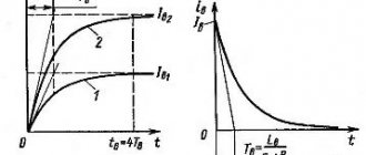
Natural mechanical characteristic. The natural mechanical characteristic is described by formula (1.6).
At idle M = 0 and nx = U/SEF.
If Ф = const, then the equation of the mechanical characteristic takes the form:
n = nх – bМ, (1.8)
where b = Rya/SEF.
From (1.8) it follows that the mechanical characteristic (Fig. 1.26, straight line 1) is a straight line with an angle of inclination a and an angular coefficient b. Since DC motors have a small Rа, the rotation speed n changes slightly with increasing load on the shaft - characteristics of this type are called “hard”.
The current consumed by the motor from the network practically increases in proportion to the load torque. Indeed, M » Mem = Cm Iа Ф, and since the parallel-excitation motor has Ф = const, then Iа ~ М.
Speed control.
Regulating the rotation speed is possible from (1.6) in three ways: changing the magnetic flux of the main poles Ф, changing the resistance of the armature circuit Rya and changing the voltage U supplied to the armature circuit (a change in n due to a change in the load torque M is not included in the concept of regulation).
Regulation of n by changing the magnetic flux Ф is carried out using an adjusting rheostat Rр. As the resistance of the rheostat increases, the excitation current Ib and the magnetic flux of the main poles F decrease. This leads, firstly, to an increase in the idle speed nx and, secondly, to an increase in the coefficient b, i.e. to an increase in the angle of inclination of the mechanical characteristic. However, b remains small and the rigidity of the mechanical characteristics is maintained. In Fig. 1.28, in addition to natural characteristic 1, corresponding to the maximum magnetic flux Ф, shows a family of mechanical characteristics 2-4, taken at a reduced magnetic flux. From the characteristics it follows that changing the magnetic flux can only increase the rotation speed relative to the natural characteristic. In practice, the rotation speed can be increased by no more than 2 times using this method, since an increase in speed leads to deterioration in commutation and even mechanical damage to the machine.
Another method of speed control involves connecting in series with the armature an adjusting rheostat Rya.p (the starting rheostat Rp is unsuitable for this purpose, since it is designed for short-term operation). Formula (1.6) then takes the form:
n = ,
(1.9)
from which it follows that the speed at idle for any resistance Rya.r is the same, and the coefficient b and, consequently, the slope of the mechanical characteristics 5-7 increases (Fig. 1.26). Regulating the rotation speed in this way leads to a decrease in the rotation speed relative to the natural characteristic. In addition, it is uneconomical, since it is associated with high power losses (Rya.p I) in the control rheostat, through which the entire armature current flows.
The third method of regulating the rotation speed is a rheostat-free change in the voltage supplied to the armature. It is only possible when the motor armature is powered from a separate source, the voltage of which can be adjusted. Separate generators or controlled valves (thyratrons, mercury rectifiers, thyristors) specially designed for a given engine are used as a controlled source. In the first case, a system of machines is formed, called the G-D system (generator - engine), (Fig. 1.27). It is used for smooth control over a wide range of rotation speeds of powerful DC motors and in automatic control systems. A control system with controlled HC valves (Fig. 1.28) is used to regulate the rotation speed of lower-power engines. Its advantage is greater efficiency.
Regulating the rotation speed by changing U is practically only possible in a decreasing direction, since increasing the voltage above the rated voltage is unacceptable due to a sharp deterioration in commutation. From (1.9) it follows that as the voltage decreases, the no-load speed nx decreases, and the slope of the mechanical characteristics 8-10 does not change (see Fig. 1.26); they remain rigid even at low voltages. The control range (nmax/nmin) in this way is 6:1-8:1. It can be significantly expanded by using special feedback circuits.
Regulating characteristic.
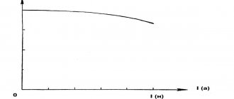
The regulating characteristic n=f(Iв) of a parallel-excitation motor is shown in Fig. 1.29.
Its character is determined by dependence (1.5), from which it follows that the rotation frequency is inversely proportional to the magnetic flux and, consequently, to the excitation current Iв. When the excitation current Iв = 0, which can happen when the excitation circuit is broken, the magnetic flux is equal to the residual Fost and the rotation speed becomes so high that the engine can be mechanically destroyed - a similar phenomenon is called engine runaway.
Physically, the phenomenon of separation is explained by the fact that the torque (1.2) with a decrease in the magnetic flux, it would seem, should decrease, however, the armature current Iа = (U – E)/Rа increases more significantly, since E (1.1) and the difference U – E decrease increases to a greater extent (usually E » 0.9 U).
Braking modes.
Motor braking modes occur when the electromagnetic torque developed by the motor acts against the direction of rotation of the armature. They can occur during engine operation when operating conditions change or are created artificially in order to quickly reduce speed, stop or reverse the engine.
The parallel excitation motor has three braking modes: generator braking with energy return to the network, back-switch braking and dynamic braking.
Generator braking occurs in cases where the armature rotation frequency n becomes greater than the rotation speed at ideal (i.e., at Mpr = 0) idle speed nx(n>nx). The transition to this mode from the engine mode is possible, for example, when lowering a load, when the torque created by the load is applied to the armature in the same direction as the electromagnetic torque of the engine, i.e. when the load torque acts in accordance with the electromagnetic torque of the motor and it picks up a speed greater than nx. If n>nx, then E>Uc (where Uc is the network voltage) and the motor current changes its sign (1.4) - the electromagnetic torque changes from a rotating torque to a braking torque, and the machine switches from engine mode to generator mode and supplies energy to the network (energy recovery ). The transition of a machine from motor mode to generator mode is illustrated by a mechanical characteristic (Fig. 1.30). Let a1 be the operating point in the motor mode; it corresponds to the torque M. If the rotation speed increases, then the operating point according to characteristic 1 from quadrant I moves to quadrant II, for example, to the operating point a2, which corresponds to the rotation speed n΄ and the braking torque – М΄.
Back-switch braking occurs in a running motor when the direction of the armature current or field current is switched to the opposite direction. In this case, the electromagnetic torque changes sign and becomes braking.
The operation of an engine with the opposite direction of rotation corresponds to mechanical characteristics located in quadrants II and III (for example, natural characteristic 2 in Fig. 1.30).
A sudden transition to this characteristic is practically unacceptable, as it is accompanied by an excessively large surge of current and braking torque. For this reason, simultaneously with the switching of one of the windings, an additional resistance Rext is switched on in the armature circuit, limiting the armature current.
The mechanical characteristic of the mode with Rext has a large slope (straight line 3). When switching to the back-to-back mode, the rotation speed n at the first moment cannot change (due to the inertia of the armature) and the operating point from position a1 will move to position a3 on the new characteristic. Due to the appearance of Mtor, the rotation speed n will quickly fall until the operating point a3 moves to position a4, corresponding to the engine stopping. If at this moment the engine is not disconnected from the power source, the armature will change the direction of rotation. The machine will begin to operate in motor mode with a new direction of rotation, and its operating point a5 will be at mechanical characteristic 3 in quadrant III.
Dynamic braking occurs in cases when the motor armature is disconnected from the network and is closed to the dynamic braking resistance Rd.t. The characteristic equation (1.6) takes the form:
n=
which corresponds to a family of straight lines 4 (for different Rd.t) passing through the origin of coordinates. When switching to this mode, operating point a1 goes to one of characteristics 4, for example, to point a6, and then moves along straight line 4 to zero. The engine armature is braked to a complete stop. By changing the resistance Rd.t you can regulate the armature current and braking speed.