Electromagnetic power and torque, angular characteristics of synchronous generators
The field of the armature winding of stator 1
has poles
Nа
and
Sа
.
2
of the excitation winding,
rotating together with the rotor N
and
S.
In steady-state synchronous mode, the fields of the armature winding and the excitation winding rotate at a synchronous speed
n1.
The pole systems of the armature and field windings are stationary relative to each other.
F
arises , tending to orient the rotor in such a way that the fields of the armature and excitation windings are directed in accordance.
The forces arising in this case can be simulated using rubber threads tending to contract 3,
stretched between opposite poles of the armature and field winding systems
.
If the machine has no load, then the opposite poles of the armature and field winding systems are installed opposite each other along the same axis and there is no electromagnetic torque.
The electromagnetic force F
acting between the poles has a radial direction.
In generator mode, the drive motor or turbine produces torque on the shaft. The generator shaft, together with the rotor field, rotates and advances the armature winding field by an angle Θ
.
As a result, the electromagnetic forces F
of attraction between the rotor and stator fields have tangential components
Fτ,
which create a braking electromagnetic torque.
As the generator load increases, the angle Θ
increases, i.e. the stator field lags behind the rotor field to a greater extent.
As the angle Θ
Fτ
increase within certain limits .
The maximum torque corresponds to the value Θ
= 90°, when the axis of the rotor poles is located between the axes of the poles of the total flow.
If the machine goes into motor mode, then an external torque acts on the shaft, braking the rotor. As a result, the motor shaft, together with the rotor field, rotates and lags behind the stator field by an angle Θ.
In this case, the tangential components of the electromagnetic forces change direction and a rotating electromagnetic torque of the motor arises.
Thus, during the transition from the generator mode to the motor mode, the steady rotation speed of the machine does not change, but the sign of the angle Θ changes.
In the stator of a synchronous generator, electrical losses occur in the Ray
and losses in the core steel.
The electromagnetic power transmitted from the rotor to the stator by the electromagnetic field is equal to:
In synchronous machines of high and medium power, losses in the Ray
and losses in the steel core
Рс
are small compared to the electrical power supplied by the generator to the network.
If we neglect them, then the electromagnetic power will be equal to the useful power P2
supplied by the generator to the network:
Angular characteristics of a synchronous generator
Electromagnetic power of a non-salient-pole synchronous generator during its parallel operation with the network
where θ is the angle by which the longitudinal axis of the rotor is shifted relative to the longitudinal axis of the resulting machine field (Fig. 21.4).
Electromagnetic power of salient pole synchronous generator
where xd=xad+x1 and xq= xad+x1 are the synchronous inductive resistances of the salient-pole synchronous machine along the longitudinal and transverse axes, respectively, Ohm.
Dividing expressions (21.7) and (21.8) by the synchronous rotation frequency ω1, we obtain expressions for electromagnetic moments:
non-salient pole synchronous machine
salient pole synchronous machine
where M is the electromagnetic moment, N*m.
Analysis of expression (21.10) shows that the electromagnetic torque of a salient pole machine has two components: one of them is the main component of the electromagnetic torque
the other is the reactive component of the torque
The main component of the electromagnetic torque Mosn of a salient-pole synchronous machine depends not only on the network voltage (Mosn ≡ U1), but also on the emf E induced by the magnetic flux of the rotating rotor F in the stator winding:
This indicates that the main component of the electromagnetic torque Mosn depends on the magnetic flux of the rotor: Mosn ≡ F. It follows that in a machine with an unexcited rotor (F = 0) the main component of the torque Mosn = 0.
The reactive component of the electromagnetic torque Мр does not depend on the magnetic flux of the rotor poles. For this component to occur, two conditions are sufficient: firstly, that the rotor of the machine has pronounced poles (xq ≠ xd) and, secondly, that the mains voltage is applied to the stator winding (Мр =U1 2). The physical essence of the reactive torque will be described in more detail in § 23.2.
As the load of the synchronous generator increases, i.e., as the current I1 increases, the angle θ increases, which leads to a change in the electromagnetic power of the generator and its electromagnetic torque. Dependencies Rem = f
(θ) and M =
f
(θ), presented graphically, are called the angular characteristics of a synchronous machine.
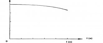
Let's consider the angular characteristics of electromagnetic power Rem.i = f
(θ) and electromagnetic moment Mya =
f
(θ) of a salient-pole synchronous generator (Fig. 21.5). These characteristics are constructed under the condition of constant network voltage (Uc = const) and magnetic excitation flux, i.e. E= const. From expressions (21.9) and (21.11) we see that the main component of the electromagnetic torque Mosn and the corresponding component of the electromagnetic power change proportionally to the sine of the angle θ (graph 1), and the reactive component of the torque Мр and the corresponding component of the electromagnetic power changes proportionally to the sine of the angle 2θ ( schedule 2). The dependence of the resulting moment Ма = Mosn + Мр and electromagnetic power Rem on the angle θ is determined by graph 3, obtained by adding the values of the moments Mosn and Мр and the corresponding powers along the ordinates.
The maximum value of the electromagnetic moment Mmax corresponds to the critical value of the angle θcr.
Rice. 21.5. Angular characteristic of a synchronous generator
As can be seen from the resulting angular characteristic (graph 3), when the load of the synchronous machine increases to values corresponding to the angle θ≤θcr, the synchronous machine operates stably. This is explained by the fact that at θ≤θcr, an increase in the generator load (increase in θ) is accompanied by an increase in the electromagnetic torque. In this case, any steady load corresponds to the equality of the torque of the prime mover M1 to the sum of the opposing torques, i.e. M1= Мя+ M. As a result, the rotor speed remains unchanged, equal to the synchronous speed.
At a load corresponding to the angle θ≤θcr, the electromagnetic moment М decreases, which leads to a violation of the equality of the torque and counteracting moments. In this case, the excess (unbalanced) part of the torque of the prime mover ΔМ = M1 - (Мя + M) causes an increase in the rotor speed, which leads to a violation of the synchronization conditions (the machine goes out of synchronism).
The electromagnetic moment corresponding to the critical angle value (θcr) is the maximum Mmax.
For salient-pole synchronous machines θcr = 60÷80 el. hail
The angle θcr can be determined from the formula
cos θcr = √β 2 +0.5 – β (21.14)
For non-salient-pole synchronous machines, Мр = 0, and therefore the angular characteristic is a sinusoid and the angle θcr = 90°.
The ratio of the maximum electromagnetic torque Mmax to the nominal Mnom is called the overload capacity of a synchronous machine or the static overload coefficient:
Neglecting the reactive component of the torque, we can write
i.e., the smaller the angle θnom corresponding to the rated load of a synchronous machine, the greater its overload capacity. For example, for a turbogenerator θnom = 25÷30°, which corresponds to λ = 2.35÷2.0.
Source
Powers and moments of synchronous generator (SG).
As is known, the power of a synchronous machine (SM) is determined by the relation:
When the generator operates under load, its mode is determined by the following values:
1. mains voltage (U);
2. generator’s own EMF (Eo);
3. angle
(U and Eo).
In addition to the well-known electrical, angle
It also has a so-called constructive interpretation. Namely, the angle is determined by the angular position of the rotor poles relative to the resulting rotating magnetic flux of the stator. So, P=f(U, Eo, ). At the same time, when the generator operates with a network of infinitely high power, then U=const, f=const. In addition, if a synchronous generator (SG) operates in stationary mode, then its own EMF Eo=const. That is, the power of the synchronous generator (SG) P in this most common case depends only on the angle .
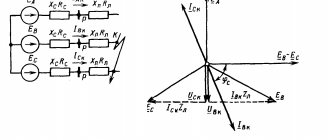
Let us obtain a general formula for the power of a synchronous generator (SG) for a salient-pole synchronous generator (SG) based on its simplified vector diagram under the assumption that Ra = 0 ( r
Where can we express the component currents:
By carrying out transformations taking into account formulas (20) and (21), one can ultimately obtain a general power formula for a salient-pole synchronous generator (SG):
Angular characteristics of a synchronous generator.
Dependencies
presented graphically are called the angular characteristics of a synchronous machine.
This active power characteristic was obtained under the condition:
1 - the main component of the em moment (changes proportionally to the sine θ)
2-reactive torque component (changes in proportion to the sine of 2θ)
3 - final (resulting) torque curve and, accordingly, power.
| The values of the components of the armature current based on the vector diagram: Substituting this into the previously defined expression for power we obtain:
|
The equation for the angular characteristic of the active power of a salient-pole SM has two components. The first component depends on both the voltage and the emf created by the magnetomotive force of the field winding. The second component does not depend on the excitation of the machine. It arises due to differences in inductive reactance along the longitudinal and transverse axes. Due to this component, the salient-pole generator can operate in parallel with the network even in the absence of excitation current, when E = 0. In this case, the magnetic flux will be created only by the armature reaction. At nominal excitation, the amplitude of the second power component is 20-35% of the amplitude of the first, main component.
§3 Electromagnetic power of a synchronous machine
P1 Simplified equivalent circuit and vector diagram of a non-salient-pole synchronous generator
As follows from the energy diagram, the electromagnetic power of the synchronous generator P em is less than its useful power P 2 by the amount of losses in the copper and steel of the stator. But already in machines of average power these losses amount to only about 1 percent of the rated power of the machine. On this basis, they can be neglected and the electromagnetic power of the machine can be considered equal to its useful power. (1)
This simplification corresponds to an equivalent circuit without resistor r, which takes into account stator losses, and a vector diagram presented in Figure 19.
Simplified equivalent circuit and vector diagram of a salient pole SG.
In addition, here the inductive reactances taking into account the armature reaction x a and the leakage fluxes xs are combined into the inductive reactance x c, called the synchronous resistance of the stator winding. . (2)
In a simplified vector diagram, the angle
is called the angle of mismatch between the rotor poles and the resulting field of the machine.
P2 Electromagnetic power of a synchronous machine
Let us draw a perpendicular ak from the end of the vector E 10 to the direction of the vector U. This perpendicular forms an angle with the vector jI 1x c. It follows that . Or . Substituting this expression into the power formula (1) we have:
Questions for self-control.
- Why is it possible to consider the electromagnetic power of a machine equal to its useful power? (1)
- What is the synchronous resistance of the stator winding? (2)
- How is the electromagnetic power of a synchronous machine related to the pole misalignment angle? (3)
Source
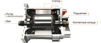
Synchronous motor
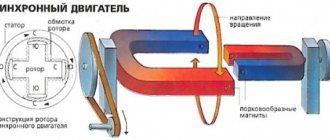
Operating principle of a synchronous motor.
Since a synchronous machine has the property of reversibility, the design of the motor is practically no different from the design of a synchronous generator. However, the interaction of the elements now corresponds to the operating principle of the engine.
Electrical active power P is consumed from the network, as a result of which current flows through the stator windings. The current, as in the generator, creates the MMF Fst, and it creates the flows Фd and Фр,я, inducing EMF and in the stator winding.
An excitation current Iв flows through the rotor winding, its MMF Fв creates a magnetic flux of the rotor Ф0. Rotating with the rotor, the F0 flow, in accordance with the law of electromagnetic induction (EMI), induces an EMF in the stator winding, which is directed against the network voltage. The sum of the EMF, taking into account the voltage drop across the active resistance of the stator winding, balances the network voltage. Magnetic fluxes Ф0, Фd and Фр,я form the resulting magnetic flux of the milling cutter motor.
The motor shaft is coupled with the shaft of the working machine PM (for example, with the spindle of a metal-cutting machine), which consumes mechanical energy and creates a moment of resistance Mc. As a result of the action of the braking torque Mc, the rotor poles lag behind the poles of the resulting stator field (see Fig. 4.6).
In motor mode, the resulting magnetic flux of the Milling motor is leading; rotating, it drags the rotor along with it, creating a torque M of the engine, overcoming the braking torque Mc of the mechanical load.
Equation of Kirchhoff's second law for the stator winding.
In motor mode, a synchronous machine consumes current from the network, which is directed towards the EMF (Fig. 4.14a).
Equation written according to Kirchhoff's second law for the phase of the stator winding
, (4.4)
shows that the back-EMF and the inductive voltage drop jXsin balance the network voltage (assumed =0).
Vector diagram of a synchronous motor.
The vector diagram is constructed according to equation (4.4) in Fig. 4.14, b. As a result of the action of the mechanical load Mc, the axis of the magnetic flux of the rotor Ф0 lags at an angle from the axis of the resulting magnetic flux of the Mill. Therefore, in motor mode, the EMF vector lags in phase by an angle from the network voltage vector. A comparison of the vector diagrams of a synchronous motor (Fig. 4.14b) and a synchronous generator (see Fig. 4.13) shows that the angle changes its sign. When constructing a vector diagram of the engine, the vector is taken as the original one.
The current vector is 90° out of phase from the vector jXsyn.
Power and torque of a synchronous motor.
The active power consumed by a three-phase synchronous motor from the network is equal to three times the phase power.
If we neglect losses, which are relatively small, then the active power consumption is equal to electromagnetic power, i.e., the power transmitted by the magnetic field from the stator to the rotor, where is the phase shift angle between the current and the EMF.
From the triangles Oca and acb of the vector diagram in Fig. 14.14, b it follows that the segment , where is the scale factor. Substituting the value of IcosΨ into the expression for Rem, we obtain for the mechanical power on the motor shaft.
Mechanical torque on the motor shaft,
(4.5)
where is the angular velocity of the rotor; Mmax = - maximum torque developed by the engine. At a constant network voltage Uc, the maximum motor torque depends only on the EMF E0, i.e. from the rotor excitation current Iв.
Angular and mechanical characteristics .
The dependence of the torque of a synchronous machine on the load angle at Uc = const is called the angular characteristic of the machine. The angular characteristic (Fig. 4.15) in accordance with (4.5) has the form of a sinusoid.
In the motor mode, the angle is positive, therefore, on the graph, the motor mode corresponds to a positive half-wave of the sine wave. In generator mode, the angle is negative; it corresponds to the negative half-wave of the sine wave. In the load angle range -90°<<+90° (the sine wave branch is shown by a solid line), the operation of the machine, both in motor and generator modes, is stable, and in the sections of the curve shown by the dashed line, it is unstable.
In a stable part of the characteristic, the machine has the property of self-regulation, i.e. when the load torque changes, the machine torque automatically changes in the same direction, and in such a way that in the new steady state, an equilibrium stable state is achieved between them.
Thus, in the motor mode, with an increase in the mechanical load Mc, the rotor slows down, the load angle increases and, in accordance with the angular characteristic, the motor torque M increases. If M = Mc, a new steady state will occur, and the rotor rotation speed will remain unchanged and equal to the magnetic field rotation frequency stator; Only with this equality there is electromagnetic interaction between the poles of the rotor and stator, which determines the torque M of the machine.
The maximum torque Mmax of the machine is also critical. If you load the engine so that Mc> Mmax, then the load angle will become greater than 90°, the operating point will move to an unstable section of the angular characteristic. The torque of the engine M will begin to decrease, the rotor will slow down, the engine will get out of synchronization and may stop.
Similar phenomena occur in generator mode. The machine's exit (“falling out”) of synchronism is an unacceptable phenomenon; it can lead to severe distortion in the nominal mode of the load angle and torque reserve and active malfunction in the electrical network. Therefore, synchronous machines are designed so that the power is at least 1.65.
The mechanical characteristic of a synchronous motor is the dependence of the rotation speed on the motor torque. In a synchronous motor, the rotor speed is constant and does not depend on the load. Therefore, the mechanical characteristic n(M) (Fig. 4.18) is a straight line, parallel to the abscissa axis.
Controlling the power factor of a synchronous motor.
A synchronous motor, unlike an asynchronous one, has a valuable property for the electric power industry - it allows you to regulate the reactive power consumed from the network. When the engine operates with a constant mechanical load on the shaft, i.e. Мс = const with Uc = const, then the active power P consumed by the motor from the network is constant:
If the excitation current is changed under these conditions, the EMF of the stator windings changes so that the active component of the current Icosφ and the EMF component remain unchanged (Fig. 14.17).
When the excitation current changes, the vector slides along the straight line ab, the position of the vector jXsin and the phase shift angle φ between the current and the network voltage change, and, due to the fact that the end of the current vector slides along the straight line cd.
When the motor excitation current is small (underexcitation), =, the current lags in phase and the motor consumes reactive power. At a certain, relatively large excitation current = and the current is purely active.
On the contrary, when overexcited, the current vector is ahead of the voltage vector in phase; the current consumed by the motor from the network has a capacitive component. The latter is very valuable, since the capacitive current compensates for the inductive currents consumed from the network by other consumers (asynchronous motors, various types of coils, etc.), and thereby improves the cosφ of the entire network. Typically synchronous motors operate with overexcitation at .
U-shaped characteristics.
The dependences I(Iв) at Uc = const and Р = const are called U-shaped characteristics. In Fig. 4.18 shows three such characteristics for the cases P = 0 (idle mode), some power P1> 0 P2> P1. The minimum current in the characteristics corresponds to the active current consumed by the motor, the left branches correspond to the overexcited motor and capacitive current.
As the excitation current Ib decreases, the EMF E0 decreases and the angle increases (Fig. 4.17).
Dashed curve AB in Fig. 4.18 represents the stability limit at which =90°.
The most economical mode for the synchronous motor itself is the operating mode with , since the motor develops a given mechanical power at the lowest, purely active stator current.
Rice. 4.17 and 4.18
Typically, in operation, a synchronous motor is overexcited in order to improve the cosφ of the network. The overexcitation mode is also beneficial in that the angle decreases and the overload capacity of the engine increases. At the same time, it should be taken into account that the stator windings of the motor are designed for a certain current in terms of heating. Therefore, the more the motor is loaded with active current Ia (which determines the mechanical power and torque on the shaft), the less is the possibility of using the motor as a generator of reactive (capacitive) power due to the reactive component of the current Ip.
Synchronous compensators.
Synchronous compensators are synchronous machines specifically designed to improve the power factor (cosφ) of an electrical network. They operate without mechanical load on the shaft (current Ia is small) in an overexcited mode (the right branch of the U-shaped characteristic P = 0 in Fig. 4.20). Since synchronous compensators operate idle and are loaded only with reactive current Ip, they have a lightweight mechanical structure and, therefore, smaller dimensions and weight.
Starting a synchronous motor.
Starting a synchronous motor is fraught with difficulties. If the stator winding is connected to a three-phase network, and the excitation winding is powered from a constant voltage source Uв (Fig. 4.19), then the rotor will not budge - due to the inertia of the rotor, the rotating field of the stator does not have time to engage with the stationary field of the rotor.
The so-called asynchronous starting of a synchronous motor has become widespread. To carry out asynchronous starting, the rotor of a synchronous motor is equipped with a special starting squirrel-cage winding made of copper or aluminum rods of the squirrel cage type of an asynchronous squirrel-cage motor. The engine is started as follows (Fig. 4.19).
First, the excitation winding of a synchronous motor is closed to the starting rheostat Rп, the resistance of which is 8–10 times greater than the resistance of the excitation winding (if you leave the excitation winding open, then when starting, the rotating stator field will induce a significant EMF, dangerous for insulation).
When the stator winding is switched on to three-phase voltage, the motor, due to the short-circuited winding, begins to operate as asynchronous. When the engine rotor speed reaches approximately 95% of the synchronous rotation speed of the stator field n0, the starting rheostat Rп is turned off, and the rotor field winding is switched on to a constant voltage Uв.
Since now the rotation frequency of the stator field differs slightly from the frequency of the rotating rotor field, the poles of the stator and rotor fields interact, the motor is drawn into synchronism and begins to operate as synchronous.
In the workplace, i.e. in synchronous mode, currents do not arise in the starting short-circuited winding and it does not participate in the operation of the machine. However, with short-term shocks of the mechanical load on the shaft in the starting winding, currents are induced and create a torque that damps rotor oscillations.
Advantages, disadvantages and applications of synchronous motors.
The advantage of synchronous motors over asynchronous ones is that, thanks to excitation from an independent direct current source, they operate at a high power factor (up to ) and even with a leading current. This circumstance allows you to increase the cosφ of the entire network. In addition, operating a motor with a high cosφ ensures a reduction in current consumption and losses in a synchronous motor compared to an asynchronous motor of the same power and, therefore, higher efficiency.
Finally, the torque of a synchronous motor is proportional to the line voltage Uc. Therefore, when the voltage in the network decreases, a synchronous motor retains a greater overload capacity than an asynchronous one, and, therefore, has greater reliability.
At the same time, a synchronous motor is more complex in design than an asynchronous motor of the same power, and therefore more expensive. Synchronous motors must have a direct current source (a special exciter or rectifier); starting them is more difficult than asynchronous ones. Frequency regulation is the only way to regulate the angular speed of the rotor of a synchronous motor.
However, the advantages of synchronous motors are so great that with powers above 100 kW, it is advisable to use them wherever it is not necessary to frequently stop and start mechanisms or regulate their speed. Currently, they are used to drive converter units, compressors, pumps, fans, mills, crushers, unregulated rolling mills, etc.
Domestic industry produces three-phase synchronous motors with power from 20 kW to several tens of thousands of kilowatts at rotation speeds from 100 to 1000 rpm in salient-pole design and at 1500, 3000 rpm in non-salient-pole design, with different designs according to the method of protection from external influences ( open, protected, closed, etc.), with different operating positions of the shaft (horizontal, vertical) and with different excitation systems: from a direct current generator located on the same shaft with the engine, from thyristor rectifiers, etc.