What is an electric meter?
An electric meter is a device for recording the user's electricity consumption, measured in kWh.
An electric meter is considered the responsibility of the energy company that supplies electricity to an apartment or private house, but in practice, the installation or replacement of such devices falls entirely on the shoulders of its consumers.
Models of electricity meters can differ in their design and principle of operation, designed for a single-phase or three-phase network, for one or more tariffs, and are also designed for different current power and accuracy class for measuring consumed electricity.
Installing a high-precision and high-quality device allows you to achieve significant cost savings when paying for electricity. Therefore, in order to choose the optimal electric meter, it is important to understand the main technical characteristics of the models on the market.
Principle of operation
Induction counter device. (Click to enlarge)
An induction meter has two coils: current and voltage. The current coil is connected in series, and the voltage coil is connected in parallel.
These two coils form an electromagnetic flux. For a current coil it is proportional to the current strength, for a voltage coil it is proportional to the mains voltage.
The electromagnetic field rotates an aluminum disk, which, using a gear and worm gear, is connected to the counting mechanism and drives it. When the meter operates, the following pattern is observed: “the higher the power consumption, the faster the disk rotates along the axis.”
Design and principle of operation of electricity meters
According to their design and operating principle, electric meters are divided into induction and electronic.
Induction counter
This is an electromechanical type of device. It appeared a long time ago and is now considered obsolete. Inside such a counter there is a metal disk connected to a counting mechanism and two magnetic coils. The magnetic field created by the coils rotates the disk, and the number of its revolutions is used to record the kilowatts of electricity used.
Induction models of electric meters are quite easy to use, have a low cost and a long service life. But the devices also have significant disadvantages, namely:
- they may have low measurement accuracy (low power consumption loads may not be taken into account);
- There is no possibility of multi-tariff calculation of kWh.
Electronic counter
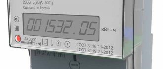
Induction meters are now being widely replaced by electronic models, which appeared on the electrical market relatively recently. In electronic types, the mechanism for calculating electricity is not performed mechanically, but using a microcontroller. They do not contain mechanical parts, but contain microcircuits, voltage and current sensors. The body has a digital display.
These devices are considered more accurate in measuring electricity consumption. In addition, the advantages of electronic meters are the possibility of multi-tariff metering, their compact size and additional functionality: an electronic meter can have a memory for storing consumption indicators, as well as built-in feedback channels (GSM, IP, etc.), which will allow them to be used in the system automatic consumption metering, which is going to be introduced in the near future.
However, these models are more expensive than induction models and are considered less reliable; for example, the date and time may be lost in them, important parameters for tariffs with several counting zones.
Operating principle of an electronic electricity meter
Until recently, all measurements of consumed electricity were carried out using induction meters. Gradually, with the development of microelectronics, a significant shift occurred in the improvement of metering and monitoring devices for consumed electricity. Modern digital electronic control systems were created using the latest microcontrollers. This made it possible to significantly increase the accuracy of measurements, and the absence of mechanics significantly increased the reliability of the meter.
A special element base and methods for processing incoming information have been developed for electronic electricity meters. After processing digital data, it became possible to simultaneously calculate not only active but also reactive power
This factor becomes important when organizing metering in three-phase networks. As a result, multi-tariff electricity meters were created that take into account the accumulated energy during a certain time of day
These devices are capable of automatically determining a particular tariff.
The simplest digital system based on a conventional microcontroller is used in cases where it is necessary to measure pulses, display information on the display and provide protection in the event of an emergency failure. Such devices are digital analogues of mechanical electricity meters. In this system, the signal is received through certain transformer sensors. Next it goes to the input of the converter microcircuit.
The frequency signal received at the input of the microcontroller is collected at the output of the microcircuit. The microcontroller counts all received pulses and converts them into the received amount of energy (Wh). As incoming units accumulate, their total value is displayed on the monitor and recorded in internal flash memory in case of power failure or other failures. This allows for continuous recording of electricity consumption.
The multi-tariff electronic electricity meter operates according to its own algorithm. The serial interface allows you to exchange information with the outside world. With its help, tariffs are set, a time timer is set and turned on, information about accumulated electricity is received, etc. Non-volatile RAM is divided into 13 data banks that store information about the amount of energy accumulated at different tariffs. The first bank takes into account all the energy accumulated since the meter started operating. The next 12 banks record savings for the previous 11 months and for the current period.
Thus, the principle of operation of the electric meter in the electronic version allows you to change tariffs in accordance with a predetermined schedule. Through a special connector you can connect to the device and find out the amount of electricity paid by the consumer.
{SOURCE}
Mounting the electricity meter
Models of electricity meters also differ in the way they are mounted. Manufacturers produce devices with the ability to install them on DIN rails or with bolted fasteners.
The first mounting option is well suited for placing meters in electrical panels that are installed inside buildings and premises. Models with this type of fastening generally have a modular structure, which allows them to be easily mounted on a DIN rail either in a separate box or in a common electrical panel together with other devices: circuit breakers, RCDs, etc.
In addition, some manufacturers of modular electric meters add special strips to their delivery kit for convenient mounting of the device on the back wall of the electrical panel.
Electric meter models with bolt fixation are usually used in outdoor electrical panels, in which the device is screwed to its rear wall.
Note that different types of fastening of electric meters are determined only by the convenience of their installation; they do not affect the quality of contact in any way.
Single-phase or three-phase meter
Depending on which electrical network is installed in the house, a single-phase or three-phase electric meter is selected:
- Single-phase models are designed for a 220 V network. As a rule, their body has four terminal blocks for connecting wires: two for the input (phase and neutral) and the same two for the output.
- Three-phase devices are designed for connection to a 380 V network. For this purpose, there are eight terminal holes on their body: four (three phases and neutral) for the input and output.
Taking readings
Electromechanical meters are equipped with a digital drum that displays electricity consumption in kilowatts. You can submit this data to the settlement service or make calculations yourself.
Depending on the model, 5 or 7 numbers appear on the reel display, with the last one separated from the rest by a comma and highlighted in color. When accounting, you do not need to count tenths and hundredths of kilowatts - only whole numbers. The resulting kilowatt consumption per month is multiplied by the cost of 1 kilowatt and the amount that must be paid for electricity is obtained.
Electric meter accuracy class
Each electric meter model has an electricity metering accuracy class, which indicates the possible percentage deviation of the calculated kWh from the true amount of energy consumed.
Every electrical appliance has some kind of error in its readings. In this case, the accuracy class is the maximum error. The higher the error rate, the more inaccurately the device will calculate the electricity consumption of a weak load.
Currently in stores you can find models with accuracy classes 0.5, 1 and 2. Products with accuracy classes 2.5 or less are no longer sold. If they are installed, the servicing energy company will require them to be replaced with models with a higher accuracy class.
Induction electricity meters
As mentioned above, an induction electric meter operates on the basis of an induction mechanism, the diagram of which is shown below:
So, it consists of two stationary coils (windings) 1 and 2, which in space are shifted relative to each other by an angle equal to 90 0. Accordingly, the magnetic fluxes flowing through the windings, when connected to the network, will be shifted relative to each other. As a result, a traveling magnetic field will arise, which generates a torque that will begin to rotate the aluminum disk 4 located in the magnetic field of the coil. To avoid inertial rotation of the disk, after removing the voltage from the coils, or too fast rotation at minimum load, the disk will also be affected by a permanent magnet 3, which will provide braking torque. The average torque value will be:
Like a regular wattmeter, the electric meter has two windings, current and voltage. The current winding is made of a thick wire corresponding to the rated current and is connected in series to the circuit.
The voltage winding is made of a thin wire (0.06 - 0.12 mm) with a large number of turns and is connected to the circuit in parallel.
All these windings are already located inside the device and do not require a special connection circuit. It has only two input wires (for single-phase phase - zero) and output. The meters have an accuracy class of 1.0; 2.0; 2.5. They can be produced for various currents with voltages of 127V, 220V. Also three-phase can be 127V, 220V, 380V, as well as for currents up to 2000 A and 35 kV but connected through instrument transformers.
The operating principle of three-phase induction is similar to single-phase, but since when using three-phase systems, various connection patterns are possible (triangle, star), it is necessary to first study the capabilities of the selected device.
Electric meter current
All models of electric meters have different current values, which are always indicated on the body of the electric meter, for example, 5-60 A or 5(60) A, where 5 is the output current value for the current transformer, and 60 is the maximum direct current. A current transformer is used in cases where the load exceeds the direct current.
For example, if there is a 5(60) electric meter (current up to 60 Amperes), and a current of 100 A flows through the phase, then the meter clearly cannot withstand this, so we buy a current transformer with a characteristic, for example, 100:5 (when in the circuit load current flows 100 Amperes, and the transformer delivers 5 Amperes to the meter), and the meter recalculates this consumption data into 100 Amperes. At the same time, such a huge current does not flow through the meter itself. Note that this information is relevant for industries, large buildings and premises; such capacities are not found in everyday life.
When choosing a suitable meter model, it is important to focus on the value of its maximum current. This indicator will depend on the power of the input machine. In this case, there is no technical sense to limit the upper current value.
Some users mistakenly believe that the current values of the electric meter will affect the accuracy of the calculation of electricity consumption. However, for example, meter models with a maximum current of up to 60 A and up to 100 A will perform the measurement in the same way. The difference between the models will be in their design and, accordingly, in price: meters under 100 A will have a larger size and corresponding connectors for wires designed for a higher current. Therefore, when the current does not exceed 60 A (for example, a 25 A input circuit breaker), there is no point in purchasing a larger and more expensive electric meter.
Induction (mechanical) electricity meters
Fig.1. Induction single-phase electric meter
Counters with a rotating disk are familiar to almost everyone. These are the ones that have a rotating wheel behind the transparent panel. Surely many have observed the speed of its rotation more than once - the higher the speed, the greater the energy consumption. And the counter readings are indicated by numbers on special reels.
The operating principle of such counters is as follows. The electric meter has 2 coils (Fig. 2 - 1 and 4 indexes) - a voltage coil (serves as an alternating current limiter, a barrier to interference, etc., creates a magnetic flux commensurate with the voltage) and a current coil (creates an alternating magnetic flux commensurate with the current ).
Fig.2. Operating principle of an induction electric meter
The magnetic fluxes created by the coils penetrate through the aluminum disk (Fig. 2, pointer 5). In this case, the flows created by the current coil penetrate the disk several times due to its U-shape. As a result, electromechanical forces appear, which rotate the disk.
Next, the disk axis interacts with the counting mechanism in the form of a worm (gear-screw) transmission (Fig. 3), which transmits the necessary signals and information to the digital reels. The higher the disk torque, the higher the power of the supplied signal (the torque is equal to the power of the network), and therefore the higher the power consumption.
Fig.3. Worm-gear
When the power of the supplied electromagnetic signal decreases, the permanent braking magnet comes into action (Fig. 2, pointer 3). It evens out fluctuations in the disk rotation frequency due to interaction with vortex flows. The magnet creates an electromechanical force opposite to the torsion of the disk. This causes the drive to slow down or stop altogether.
This group of meters is the cheapest and simplest. Induction electricity meters were widely used in Soviet times (and to this day, most apartments have just such devices installed). But gradually they are being replaced by electronic meters due to a number of disadvantages of induction devices. For example, an induction electric meter cannot take readings automatically, and there is often an error in the readings.
Advantages and disadvantages of induction meters
Advantages
- Reliable to use
- Long-term service life of the meter
- Independence from power fluctuations
- Cheaper than electronic ones
Flaws
- The accuracy class is quite low - 2.0; 2.5
- There is practically no protection against theft of electrical energy
- High self-current consumption
- At low loads the error increases (the lower the accuracy class, the greater the error)
- When metering several types of electricity (active and reactive), there is a need to use several energy metering devices
- Energy metering is carried out in one direction
- Large dimensions of devices
meter protection
When choosing an electric meter model, it is important not to forget about its protection class - IP. To install the device indoors in a country house, office or apartment, models IP21, IP31 or IP32 are suitable. For outdoor placement, devices with protection IP54 and higher are suitable.
In addition, it should be taken into account that electric meter models are designed for different operating ambient temperatures. Modern meter models basically have a protection level of at least IP51, and an operating temperature range from -40 to +55 or even wider.
Single-tariff or multi-tariff meter
The choice of electricity meters for this parameter will depend on the location of its installation. If the device is planned to be placed in a country house, then SNT, as a rule, applies only one tariff for electricity consumption.
In apartments, in village houses and cottage communities, multi-tariff electricity meters are used with a different number of tariff zones: two-tariff or three-tariff (used when the daytime zone is divided by peak hours).
Today, in private houses and apartments, the most popular are two-tariff models, which record electricity consumption readings in two time zones - daytime (peak) and nighttime.
Operating principle of an induction meter
Until recently, induction meters were an integral part of electrical networks in apartments. The counting device in these devices is represented by a rotating aluminum disk and digital drums that display electricity consumption indicators in real time.
The operating principle of such devices is quite simple. The electromagnetic field arising in the meter coils interacts with the disk, which acts as a movable conductive element. In a single-phase induction meter, one of the coils is connected in parallel to the voltage winding, which serves as an alternating current network. Another coil is connected in series between the current winding or load and the electricity generator.
The action of currents flowing through the windings leads to the creation of alternating magnetic fluxes crossing the rotating disk. Their value is a proportion between the current consumption and the input voltage. In accordance with the disk itself, eddy currents arise, flowing in the direction of magnetic fluxes.
Eddy currents and magnetic fluxes begin to interact with each other in the disk. As a result, an electromechanical force appears, which leads to the creation of a rotating moment. Thus, a proportion arises between the resulting torque and the product of the two magnetic fluxes arising in the current and voltage windings, multiplied by the sine of the phase shift between them.
Normal operation of an induction electric meter is possible only if there is a phase shift of 90 degrees. Such a shift can be obtained by decomposing the magnetic flux of the voltage winding into two parts. It turns out that the device disk rotates with a frequency proportional to the actively consumed power. Therefore, the direct energy consumption will be in proportion to the number of disk revolutions. The resulting consumption data is transmitted to a mechanical metering device, the axis of which is connected to the axis of the movable disk using a gear drive. This design ensures synchronous rotation of both elements.
Electric meter release date
This parameter is also taken into account when purchasing the device. A single-phase electric meter must be manufactured no more than 2 years before its installation, and a three-phase one - no more than 1 year, respectively. Otherwise, the energy sales company may not accept it for accounting.
In addition, when purchasing a suitable device model, you must pay attention to the integrity of the factory seal, which guarantees that the electric meter is working correctly. The fact is that any electricity metering device, after being assembled in production, undergoes a mandatory state inspection of measurement accuracy, after which it is sealed with a seal indicating the date of inspection. If there is no such seal, the energy company will refuse to register it.
Markings on electricity meters
In addition to the types of meters, there are several more nuances that you should know. Any electric meter has a certain marking, conventionally designated by letters and numbers.
Fig.6. Symbols on the electric meter
| Designation | Explanation |
| WITH | Device type (meter) |
| A, R | Type of energy taken into account (active energy/reactive energy) |
| ABOUT | Single phase meter |
| 3, 4 | Number of phase wires in the network (four-wire/three-wire) |
| U | Versatility |
| AND | Type of measuring system (induction meter). Next there may be a three-digit number, which indicates the design of the meter (the design of the meter can be induction or electronic). |
| T | Tropical meter type |
| P, M | Type of execution (direct-flow - if there is no connection to a transformer / modernized). Further, there may be abbreviations such as “380/220 17A, 2001,” which means operating voltages in the wires, maximum current flow and year of manufacture. Also at the end of the inscription there may be a serial number. |
As for the accuracy class of the electric meter, these parameters determine the accuracy of the readings of consumed electricity. Apartments, as a rule, have class 2.0 meters installed, but they can be higher. What does this mean? And the fact is that your electric meter can take into account 2% more or less electricity from its own power. Or, more simply put, the meter error. The smaller the number, the smaller the error. In general, in domestic conditions, an electric meter of class 2.0 is sufficient. Higher accuracy classes are more likely to be needed in enterprises where greater energy power is needed.
So, today we don’t have to limit ourselves in choosing electricity meters. Each of them has its own specific features and functions. In this article, we examined the main features of these devices and the principles of their operation, which will help you navigate the variety of choices.
Electricity meter and voltage stabilizer
Some users are wondering if a voltage stabilizer is purchased to protect household appliances throughout the house, then what is the best way to install it: before or after the electric meter?
As you know, service electric companies prohibit any independent connection of electronic devices to the meter, since the electricity they consume will not be taken into account in any way. But installing a stabilizer after the metering device is possible anywhere, and even necessary.
The unstable voltage itself does not affect the quality of operation of the electric meter. However, it will be negative for some electrical appliances, which may have a negative impact on your electricity bill. For example, low voltage will affect the lighting sources in the house, reducing their brightness. And to increase it you will have to use lamps designed for higher power.
As can be seen from what is written above, when choosing a suitable model of an electric meter, it is necessary to take into account many important parameters that will depend on the operating conditions of the device itself. It is important to remember that choosing the wrong device can bring a lot of problems and unnecessary costs to its user. Therefore, it is better to additionally consult with a specialist before purchasing an electric meter.
How does an induction meter work?
The essence of the operation of induction electricity meters is based on the principle that a moving part is simultaneously affected by a rotating and braking torque. This moment is proportional to the accounting value, the braking moment is proportional to the speed of rotation of the moving part. An induction single-phase electricity meter consists of several elements:
- Voltage coils that are located on the magnetic circuit;
- Aluminum rotation disc;
- Transmission mechanism of the metering device;
- Current coils on the magnetic circuit;
- Permanent magnet.
The coil is made of wire with a large cross-section, which can withstand a large load. Coil turns are available in small quantities, usually 13-30 turns per coil. They are distributed in a uniform position on two magnetic cores, which have a U shape and are made of electrical steel. The core works to create a certain concentration of magnetic flux, which crosses the counting disk and rotates it.
The voltage winding is connected to the mains voltage phase and always has an operational state, along with the consumer, which is why it is called a parallel circuit. A voltage coil is required to produce a magnetic flux that will be proportional to the mains voltage. It has certain design differences from the current coil in that it has more turns, about 8000 - 12,000, and a small conductor cross-section of 0.1 - 0.15 mm2. In large numbers, the turns create a higher inductive reactance than the active resistance of the winding, which is quite important for complying with the 90° shift rule and makes it possible to reduce electricity consumption on a single-phase meter.
The magnetic flux of the current coil and the voltage coil that pass along the disk form transformation currents in it, due to which a rotating torque is created. To create a counter torque that will be proportional to the speed of the disc, permanent brake magnets are used, whose magnetic flux crosses the rotating disc of electrically conductive material.
The cutting currents generated in the disk always maintain the rotation speed in proportion to the disk. That is, when the meter operates, it follows a certain pattern: the greater the power consumption, the faster the disk will rotate along its axis. The reaction moment, which is formed when the magnetic flux interacts with the disk current, will always be proportional to the rotation speed. When the disk passes the wave that creates the braking magnet, a cutting emf is induced on it, which comes from the middle of the disk. The flux force of the braking magnet, when interacting with the disk current, is directly proportional to the cutting emf and has a direction opposite to the movement of the disk. The slowing down process depends on the distance of the magnet from the center of the disk, defined as the product of the leverage and the value of the force. That is, the rotation speed is adjusted by moving the magnet, which allows you to adjust it depending on the gear ratio.
