- P - pink.
- F - purple.
- O - orange.
- B&W - black and white.
- KB - brown and white.
- CHG - black and blue.
- K - brown.
- H - black.
- B - white.
Tractors are equipped with inductor generators, which are better adapted to difficult working conditions.
Dust, dirt, poor cooling (low speed during operation)
Almost continuous work during the working day
An inductor generator differs in that its rotor does not have an excitation winding and is simply a rotating magnetic circuit. When rotating, the rotor creates a changing magnetic field, and an emf is induced in the winding.
The generator has a stationary
excitation winding, direct current passes through it, from the generator, this current creates a strong magnetic flux, which closes through the rotating rotor.
The field winding terminals are connected so that the field current flows in the direction of magnetization of the rotor, which contains permanent magnets. If the leads of the excitation winding are mixed up, the excitation current will demagnetize the rotor and the generator will practically stop working.
The fact that the field winding does not rotate with the rotor provides an important advantage - brushes are not needed to transmit current to the rotating rotor. The brushes wear out, poor contact under them greatly reduces the reliability of the generator, so an inductor, brushless generator is more reliable.
The single-pole magnetic circuit and large magnetic gaps in the excitation system reduce the efficiency of the inductor generator compared to a classic automobile generator, where the excitation winding is inside the rotor and current is supplied to it through brushes.
A decrease in efficiency leads to a deterioration in weight and size parameters, but for tractors and heavy vehicles this is a less important quality than reliability and durability.
An alternating EMF is generated in the winding of the inductor generator, therefore, a rectifier is needed at the output of the winding - a diode bridge. Depending on the generator circuit, a three-phase or five-phase diode bridge can be used, with or without additional diodes.
An important requirement for tractor generators is that they must operate both with a battery and without a battery. For example, if the engine is started by a starter, without an electric starter, then the battery becomes unnecessary or unnecessary.
A conventional automobile generator is always excited by a battery, but a tractor generator must be provided with excitation without a battery. To reliably excite the generator, the rotor has residual magnetism, and the voltage regulator provides appropriate changes in the circuit to facilitate self-excitation.
Generator 46.3701 Made according to a circuit with a five-phase winding,
respectively with a five-phase diode bridge with additional diodes.
The five-phase circuit makes it possible to obtain higher quality rectified voltage, that is, with less ripple. This is relevant in the absence of a battery, which, like a filter, smoothes out the ripples of the rectified voltage.
The use of a circuit with additional diodes is justified by the fact that an external excitation circuit is not needed; it is closed inside the generator. In addition, if there is a battery, powering the excitation winding from additional diodes prevents accidental discharge of the battery through the excitation winding when the power is on and the engine is not running.
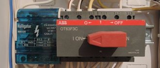
How to connect a power plant to a house via AVR
Today, electric generators with auto-start are sold. They are not cheap. But autostart is worth the money, because the whole process is automated. After a power outage, you only need to wait a few seconds until voltage appears in the house from your power plant.
Operating principle of AVR. The electric generator’s automation constantly “monitors” the voltage from the external network. If it goes missing, the ATS contactor is switched off, which connects to the stationary network of electrical consumers in your home. After this, the starter is turned on and the power plant engine starts. After it reaches rated speed, the ATS contactor is turned on, which connects consumers to the power plant.
When voltage appears in the external power supply network , the ATS switches consumers to work from it. The generator engine continues to idle for a short time and then shuts down.
Connection diagram to ATS. Cables are inserted and connected into the autostart system panel according to the diagram from the instructions or on the panel door.
is connected to the ATS through an electric meter and a power cable from the generator, as well as a control cable. From the AVR, power is supplied to the electrical panel past the electricity meter directly to the circuit breakers to which the electrical consumers of your home are connected.
Keep in mind that in most cases, the automatic start system only works at temperatures below 5 degrees Cº.
PS My advice! It is better to back up the three-phase input to the house with a single-phase generator. As practice has shown, if the load is distributed incorrectly across phases, problems arise with a three-phase generator due to the occurrence of phase imbalance in the electrical network of the house. The best option would be to connect the most important electrical appliances and lighting locations in the house to the reserved one phase.
Related materials:
- Generator for wind turbine
- How to choose a power plant
- Generator fault and repair
- Generator for home and garden
← Previous page
Next page →
comments 42 Add yours
- Valerik
:
August 22, 2014 at 07:11 pm
Hello. A generator with an automatic transfer switch is expensive, is it possible to assemble the circuit yourself?
Answer
Experienced Electrician
:
August 22, 2014 at 10:37 pm
Good evening! Of course you can. Just keep in mind that if some switch does not work or there is an error in the circuit, then a short circuit will occur with unpleasant consequences. I RECOMMEND to use the factory version - this is a guarantee of safety and reliability of work.
Answer
:
September 2, 2014 at 11:14 am
And what wires and where to connect in the ATS itself?
Answer
- Experienced Electrician
:
September 2, 2014 at 18:57
See the operating instructions or diagram on the ATS door. There must be inscriptions in the AVR itself.
Answer
:
December 11, 2014 at 04:52 pm
Hello. My boiler from the generator does not work until I supply zero from the general power supply network. What will happen if the generator is running and the lights are turned on in this case, and how can I do it differently?
Answer
- Experienced Electrician
:
October 19, 2015 at 11:20 am
Igor, hello. You need to understand why this is happening to you in such a strange way. Describe the problem, wiring diagram and what exactly are you doing to make the boiler work?
Answer
:
December 25, 2014 at 10:41 am
Why break zero when connecting a three-phase generator to a three-phase network at home? If the generator is properly grounded, you can use the mains
Answer
:
May 6, 2015 at 18:17
Is it necessary or not to install a magnetic starter in the switchboard so that the voltage from the generator does not go to the city network?
Answer
:
August 14, 2015 at 08:54
Single-phase generator with a maximum power of 5.5 kW, the wiring in the house is three-phase, is it possible to assemble three phases into a bundle plus zero, supply power to the house network in all three phases!
Answer
- Experienced Electrician
:
September 26, 2015 at 09:48
If the question is still relevant, let me know. This can be done, but it must be done through an electromagnetic starter
Answer
:
August 29, 2015 at 07:33 pm
The house has 3 f., but I bought a generator for 1 f. and now I can’t figure out how to connect it to the electrical panel at home. I heard that there are different relays, etc.
Please help with advice on how to safely connect 1 f. generator to 3 f. shield. I will turn on the generator manually!
Answer
- Experienced Electrician
:
August 31, 2015 at 14:59
Stanislav, hello. The first method, which will require an investment of money, is to buy an inverter. The principle of operation is that it converts from a single-phase network to a three-phase one. Therefore, it is connected to the terminals of the generator, and from the inverter to the panel. The second method has certain nuances. You can turn on one phase, but if you have three-phase consumers (electric motors, for example), then they will not work. The easiest way is to install another introductory machine for three phases. A phase from the generator is placed on top of it at any of the inputs (preferably the central one), and jumpers are placed on the other two inputs. That is, your upper terminals will be connected by jumpers to which the phase will arrive. From the lower terminals, the wires are connected to the main input circuit breaker. So, when you turn on the generator, you turn off the main circuit breaker and turn on the circuit breaker from the generator. Anything powered by a 220 volt network will work. A more complex method, which I call “for the fool,” involves installing one or two electromagnetic starters. You can install one that will only work when there is electricity not from a generator. This is the scheme. There is an introductory main machine. From it, three wires (three phases) go to the electromagnetic starter, from the starter the wires go to the machines. Power to the starter is taken from the input circuit breaker. That is, as soon as you lose power, the contactor will turn off. From the generator, as I said, a machine is installed, only the lower wires are no longer connected to the input machine, but to the lower terminals of the starter. But there is such a moment that when the main electricity is supplied, the starter will turn on. To avoid this, another starter is installed, powered by a generator. The purpose of this starter is to prevent the main starter from turning on. That is, the coil of the main starter must be controlled through an additional one in such a way that while the generator is running, it is impossible to turn on the main starter.
Answer
:
August 31, 2015 at 15:00
Ivan, hello. You need to calculate the power you plan to use. And then choose the cable cross-section yourself. 2.5 sq.mm - 25 A (5.5 kW), 4 sq.mm - 32 A (7 kW), 6 sq.mm - 40 A (8.8 kW), 10 sq.mm - 50 A ( 11 kW)
Answer
:
October 3, 2015 at 21:50
Good afternoon. I bought a 7 kW three-phase generator 1.5 years ago. The house has three phases, each divided into 7 kW. It was connected by an electrician who recommended that I buy a three-phase generator. Every time the lights were turned off, the generator voraciously pulled out work and burned two washing machines for me. In August of this year, during the next power outage, the generator ran for about twenty minutes and stalled. No matter how much I tormented it, it would start for no more than 5 minutes, fire and stall (it seemed like there was a problem with the carburetor). I took the generator to the service center, and they told me that everything is fine with the generator, but it is not designed to provide three phases to the house, because... It is impossible to ensure an equal load across the phases. The verdict is that you need a single-phase generator, to power the phase with everything you need. And this generator needs to be sold to someone or converted into a single-phase one. The question is, is it really impossible to use an already purchased three-phase generator to ensure minimal electricity consumption of three phases (according to 2.3KW) ?
Answer
- Experienced Electrician
:
October 4, 2015 at 06:00
Dmitry, hello. It’s still better for you to contact a service center with the question of altering the generator. It all depends on the connection diagram of the generator. It is quite possible that the generator connection diagram is a triangle, then you really need a uniform load. Read about neutral shift on the Internet and you will understand what we are talking about. If it’s a star, then there shouldn’t be any problems. This is the only explanation. But again, you can’t just switch the connection circuit to a star. Then your generator, instead of 220 volts per phase, will produce 380, and between phases there will be 660 volts. Here you need to either replace the generator or rewind the windings. You definitely won’t be able to rewind the windings. The verdict is not the most comforting. You will most likely have to sell this generator. But buy either single-phase and make it as you want, or three-phase, but such that it can work in networks with an uneven load across the phases. There is also a more complex option. If the store did not warn you that your generator is not capable of providing operation in networks with an uneven load, and you asked for precisely this purpose, and you manage to prove this, then you will be able to exchange it, and maybe even demand compensation for damage caused installation of this device (two washing machines), plus the costs of travel, service, etc., including moral damage. But naturally, this must be done through the court, and first consult whether it is worth undertaking.
Answer
:
April 16, 2021 at 08:22
There is an option to connect a 5-7 kW three-phase transformer with a 220V output to a 3-phase generator, then when loaded, the generator will be evenly loaded across the phases, that is, there will be no phase imbalance on the generator.
Answer
:
October 14, 2015 at 07:12
Hello! Out of stupidity, they allowed a short circuit on an expensive synchronous generator. When you turn it back on, everything works. there is tension. the input voltage at the time of the short circuit was 170-180. The short-circuit was short-lived for a fraction of a second. Will the gene break over time and what damage is caused to the unit from the short circuit. The instructions in the genes say short-circuit protection, the maximum short-circuit current is more than 300%, how to understand this. Thanks in advance for your answer.
Answer
- Experienced Electrician
:
October 14, 2015 at 08:28
Dmitry, hello. Over time, everything breaks. Short-circuit currents affect the winding insulation and the excitation circuit. How long was the short circuit and why is it not worth protecting? It must be there.
Answer
:
November 10, 2015 at 03:34
Greetings!
Instead of an old 3-phase generator, I bought a new one, also 3-phase. But! The output goes only to ground and three phases, but there is no zero. At the entrance to the network, everything is as expected - 5 wires. I have no idea what to do. The old generator had a 5 outlet outlet.
Answer
- Experienced Electrician
:
November 10, 2015 at 11:46 am
Alexey, hello. I'm afraid I'll just have to change the generator. There are generators that are designed to work with a non-uniform load, that is, in such a generator it is possible to turn on a light bulb on one phase and a heater on the other. And the generator that you have can only work with a load like a three-phase motor. If there is a specification and you can find out the connection diagram of the windings and it is a star, then look where the connection point of the windings goes, this will be zero. If the connection diagram is a triangle, then nothing can be done here.
Answer
:
November 14, 2015 at 07:34 pm
Good afternoon. I installed a single-phase generator in a private house. External three-phase network. I connected it through the “reversal” just like in the picture above. There are three contacts, I connected 3 phases from the network, put a phase and jumpers from the generator, but I inserted ground and zeros into the panel and on the busbars, separate zeros and separate groundings, but I have doubts whether it is possible to put working zeros from the generator and the network on one bus. All in doubt
Answer
- Experienced Electrician
:
November 14, 2015 at 20:35
Alexander, hello. You can do this. In a generator, ground is simply the body of the generator, and zero is one of the ends of the winding, at the other end, accordingly, there will be a phase at the other end. If you connect the zero directly to the zero bus, then you will have zero voltage at the second end of the winding, which is wound up, as you say, “inverted” until the generator is running.
Answer
Alexander
:
November 14, 2015 at 21:05
Thanks for the answer. I read on some website that the generator does not have a zero as such and both wires are live, which means that voltage will flow through the network zero back into the network when it is turned off and it can hit the installer at the other end, to what extent is this correct?
Answer
Experienced Electrician
:
November 14, 2015 at 10:43 pm
I'd say almost right. Theoretically, this can happen in some unknown way (taking into account the capacitive component of the earth). In fact, for someone to be hit, there must be a potential difference. When we stand on an insulating surface (torn off from the ground), we can alternately take either the phase or the ground in our hands and nothing will happen. Because we do not have potential (charge, other voltage value) for the wire that we pick up. We acquire the potential of this wire. That is, when we stand on an insulating stand and pick up a phase wire - we are a phase, zero - we are zero. Well, now let’s transfer this situation to the generator. When you turn it on, you only output zero to the external network. But according to the PUE, the zero bus must be connected by a jumper to the ground bus (in networks with a solidly grounded neutral - this is the majority of networks up to 1000 volts). Therefore, the ground and neutral wire will have the same potential. This means that a person who is standing on the ground (which is where most electric shocks occur) will have the same potential. And relative to any phase wire, if there is any current, it will be insignificant. Moreover, according to safety regulations, when carrying out work, maintenance personnel are obliged to turn off the voltage, make sure there is no voltage, GROUND all wires on the line being repaired, hang warning signs and ONLY AFTER THIS begin repair work. That is, in any case, your generator will not be grounded by you, so the maintenance personnel will not do any harm (unless, of course, the personnel are trained, but if they are not trained, then after shaking them once, they will immediately learn :))) Well, you read correctly . If in a three-phase network (single-phase, this is just a particularity, the network is still three-phase, but one of the phases is used) the neutral conductor is called zero because relative to it the voltage changes its value from plus to minus 100 times per second, then in the generator version the voltage completely changes its direction. That is, in a three-phase network we have this: the neutral conductor is always zero, the phase conductor is relative to zero in the negative period -110, in the positive period +110. Then on the generator we have in one case 0 volts on one wire, 220 volts on the other, and then these wires seem to change places. Therefore, it turns out that a single-phase generator does not have a zero as such. But three-phase has it!
Answer
Alexander
:
November 15, 2015 at 14:23
thanks for such a detailed answer.
:
November 15, 2015 at 07:57 pm
Please. Contact us.
:
November 19, 2015 at 01:42 pm
Hello. Tell me, when connecting a single-phase generator, instead of a reversing switch (from ABB, which costs a lot of money), you can install a modular switch from the TDM company (brand MP63 1P ...... - this thing is only made by Legrands, Schneiders, etc.). According to its diagram, it has three positions - connection of one or the other wire (phase of the general network or generator) and a zero unconnected position. It is simple and cheap, the scheme is also basic, but how safe is it? And the question is about zero, is it necessary to break it with the same modular switch, only to two poles or not? As I understand, when the generator is running, there will be current at zero, and if a phase is given in the main network, will there be a short circuit? Thank you, I hope I didn’t confuse anything, since I'm not an electrician myself.
Answer
- Experienced Electrician
:
November 19, 2015 at 08:54 pm
Alexander, hello. It’s quite easy to find different variations if in the search you write not a reversible switch, but a changeover switch and there are a lot of them
Well, regarding your question regarding zero, read the comment above, everything is explained there. And the answer to your question is yes, you can install a modular switch. It is better, of course, to break the zero with the same pole switch; to do this, they are fastened together and an iron pin or a special plate is placed between the two “tongues” that will unite them.
Answer
:
December 4, 2015 at 02:04
Good day! Please tell me, is it possible to connect a 6 kW single-phase generator to a panel assembled with a solidly grounded neutral (the input neutral, as in other things, the phases will be disconnected automatically) and supply power from the generator to a single-phase RCD? It is proposed to make additional grounding for the generator, followed by combining the ground with one of the generator poles to form a guaranteed zero.
Answer
- Experienced Electrician
:
December 4, 2015 at 04:24
Vadim, hello. There are no problems with this, you can connect, read the answers to your questions in the comments above, I described them in detail recently.
Answer
:
January 4, 2021 at 10:26 pm
Hello! Who can explain why, as stated above, the generator must be completely disconnected from the existing electrical network, it is necessary to disconnect not only the phase, but also the zero? If I connect a diesel power station (3-phase generator) through a three-pole changeover switch to the load, what causes this requirement, if possible, with reference to regulatory documents, and what is the danger of such a connection? More than 10 years ago, I handed over to Energonadzor (at that time) more than 30 diesel power plants in different institutions, connected precisely through a three-pole changeover switch, and there were no comments.
Answer
- Experienced Electrician
:
January 5, 2021 at 06:19
And now there are no such requirements, there is a wish. More precisely, it is not so, if there is reliable grounding and the main grounding bus is connected by a jumper to the zero working one, then there is no mandatory requirement to install a four-pole changeover switch. But, as a rule, in three-phase networks, the requirement for a jumper and grounding is mandatory. Unfortunately, articles are not always written by professionals. And to be honest, I don’t want to look for these requirements. Just believe that there is no need to install a four-pole machine if there is grounding. The same requirement applies to single-phase generators - there must also be grounding if a two-pole changeover switch is not used.
Answer
:
January 27, 2021 at 01:15 pm
Hello!!!! The question is the following: I have a single-phase generator with a built-in automatic transfer switch, how can I connect it to a 3-phase circuit at home through contactors and time relays???
Answer
- Experienced Electrician
:
January 27, 2021 at 15:43
Roman, hello. I need documentation for your generator, it usually says how to connect it. The problem is that there are two types of control, the first involves automatic control, the second does everything itself, you just need to connect the voltage input to it, and when the voltage disappears, the station starts and connects the load from the generator to the output, as soon as voltage appears, the output mains voltage is supplied and the station is turned off.
Answer
:
April 11, 2021 at 15:19
3ph+N+PE comes into the house; there is no three-phase load in the house. I want to allocate part of the load, especially the boiler, and back it up with a small single-phase 2.2 kW generator. How to correctly implement the circuit, is it necessary to ground it and how will the Uzo behave after the generator?
Answer
- Experienced Electrician
:
April 11, 2021 at 15:40
Alexander, if the generator itself has a terminal for grounding, then it must be grounded, or at least desirable. It would be more correct to assemble the circuit using contactors, taking into account that the network contactor closes only when you have no voltage on the generator contactor, and even better through a switch, which you will use to manually switch the input from the power supply or generator (it’s cheaper and easier ). To the output from the switch you either output the entire load of the house, or only the redundant line will be powered from it. That is, from the electrical panel you have the main, non-redundant consumers, then there is a line to the redundant ones, which is supplied to the first input of the switch, the second input of the switch is supplied with power from the generator, and at the output there are directly reserved consumers. Thus, you do not touch the main part of consumers and when electricity appears, until you switch the backup line to the main one, it will be powered from the reserve. The RCD will work the same whether from a generator or from the mains. The RCD is triggered by a mismatch between the incoming and outgoing currents, regardless of whether there is grounding or not. I literally just answered about the RCD here, see the latest comments.
Answer
Alexander
:
April 11, 2021 at 15:54
I want to use an inexpensive switch up to 25 A. Is it better to use a 1-0-2 cam switch or a modular three-way switch?
Answer
Experienced Electrician
:
April 11, 2021 at 16:49
It makes absolutely no difference, depending on what is more convenient for you to install, the main thing is to follow the protection rules, it is advisable to install a thermal relay to this switch and set the current to 10 amperes, if for your generator the long-term permissible mode is 2.2 kW and see what protection is on the generator, maybe additionally install a B10 or C10 automatic machine (if the starting currents are large).
Answer
:
November 28, 2021 at 16:55
good afternoon, can you tell me if the generator plus avr works in tandem with the automatic transmission?
Answer
- Experienced Electrician
:
November 29, 2021 at 17:00
Vitaly, hello. The generator and automatic transfer switch do not in any way affect the operation of the difavtomat and the difavtomat will only work if the generator is grounded. If there is no grounding, then in the event of an insulation breakdown, the voltage on the ground and the voltage on the body will acquire the same potential as soon as some kind of connecting link appears (for example, a person standing on the floor and grabbing the live body) and in this case, the RCD will trip or the difavtomat, the current must flow somewhere (in this case, return to the generator, if grounding is provided on the generator, and if there is no grounding, that is, the stator winding is in no way connected to the generator housing, then grounding will be useless).
Answer
:
November 28, 2021 at 16:58
and another question is whether it is possible to extend the control cable of the AVR with the generator; the length required is 45 meters and what cable cross-section and how many cores
Answer
- Experienced Electrician
:
November 29, 2021 at 17:02
Vitaly, here you need to consider the power that you plan to consume, the conditions for laying the cable, the number of phases, and based on this, calculate the cable cross-section and the number of cores. And of course you can lengthen it.
Answer
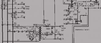
Voltage regulator Ya112B (More information about regulators Ya112)
The voltage regulator, as in other generators, turns the excitation current on and off. If the voltage rises, he turns off the excitation current, the voltage decreases, he turns on the excitation current and the voltage rises again, he turns off the excitation current again, thus maintaining a stable voltage level of about 14 Volts.
Initial excitation is possible without a battery.
The Ya 112 B regulator is distinguished by the fact that it is guaranteed to pass excitation current, even at very low voltage values at the generator output, which ensures reliable excitation of the generator without a battery.
The rotor contains permanent magnets that create a strong enough magnetic field to excite the generator.
After the generator is excited, part of the winding current is diverted through an additional rectifier to the excitation winding; for this, the output of the additional rectifier is connected at point D of the voltage regulator. The excitation current goes through point D to the excitation winding and further through point W and the open transistor of the regulator to ground.
The plus from the generator output is connected to point B of the regulator. This plus opens the voltage regulator. Based on the voltage at point B, the regulator maintains the specified value of the generator output voltage.
Point C of the regulator is used to connect a capacitor-filter. This capacitor smooths out the ripples of the reference voltage at the input of the regulator, which are quite large in the absence of a battery; the capacitor smooths out the ripples and increases the accuracy of the generator. In other tractor generator circuits, point C is used to switch “Winter - Summer”
The F phase output is used to connect the starter blocking relay. When the engine is running, accidental activation of the starter must be prevented in order not to damage the starter; for this purpose, a starter blocking relay is included in the starting circuit. When the engine is running, the alternating voltage from the generator phase reaches this relay and it knows that the starter cannot be turned on. After stopping the engine, the relay allows the starter to be turned on again.
The tractor generator does not work, what should I do?
If the tractor generator does not work, then you must first replace the voltage regulator. If it doesn't help, you'll have to disassemble it.
The winding often burns out, this can be seen from the burnt wire.
If the winding is intact, the diode bridge remains. It will have to be replaced
If the voltage regulator burns out again, the field winding may have burned out and its resistance has become too low.
When assembling the generator after repair, the connection of the excitation winding leads may be mixed up. In this case, the excitation current goes in the other direction and demagnetizes the rotor in which permanent magnets are inserted. The power of the generator drops sharply and it practically stops working. Try swapping the leads of the excitation winding, everything should be normal.
Connection diagram for the VAZ-2110 generator
On VAZ-2110, 2111 and 2112 cars, a 94.3701 generator was installed with a maximum output current of 80 Amperes and a voltage = 13.2–14.7 Volts.
Here is a breakdown of the connection diagram for the generator on the ten :
- Battery 12V;
- generator 94.3701;
- mounting block;
- egnition lock;
- battery charge indicator lamp in the instrument cluster
Why is there a powerful resistor on the voltage regulator of the G273 generator?
The initial excitation, as for all car generators, comes from the battery. When you turn on the instrument switch and the starter (VP and ST), plus 24V comes to point B
voltage regulator, the regulator opens, and current flows from the battery plus to the generator plus. If 24 Volts hits the excitation winding of a 14-volt rotor, the winding will burn out almost immediately, so then the excitation current flows through a powerful 75 Ohm resistor. When the generator is running, the excitation current no longer comes from the output of the generator, where 28 Volts operate, but from the middle point of the winding, where, as already mentioned, the voltage is reduced (this current is closed through the diode bridge, and therefore is rectified).
That is, a 75 Ohm resistor during initial excitation limits the current in the rotor winding, designed for 12 V. This resistor also protects the excitation winding and voltage regulator from overheating when the ignition is on and the engine is not running.
The positive experience of using generator circuits with additional diodes determined the release of the next generation of generators for KAMAZ. The Ya120M1 voltage regulator allows you to separate the excitation current and the regulator control current. In a circuit with additional diodes, the generator is excited through a light bulb with a small initial current, and then, when the generator is running, the excitation current comes from the generator winding and is rectified by additional diodes. This creates a short excitation current path. The circuit is not afraid of battery discharge through the excitation winding when VP and ST are turned on and the engine is not running.
The use of such generators requires the use of a light bulb to limit the initial excitation current. The light is located in the instrument panel and allows you to control the operation of the generator. In this circuit, an additional wire appears from the instrument panel to the generator.
It is useful to know that such generators already use their own rotor, designed for 28 Volts, its resistance is about 8 Ohms.
Voltage regulators for KAMAZ generators
Ya120 M1, analogues 77.3702, 443.3702 412.3702
Ya120M1I2 analog 77.3702-02
Ya120M12, analogue 77.3702-01
generator regulator G273 with a quenching resistor 75 Ohm A Y120M1 regulator is installed inside
Generator regulator with additional diodes 1312.3771. A regulator Y120M1 or Y120 M12 is installed inside
The voltage regulator is recommended Y120M12, although Y120M1 also works
How can you not do it?
The first thing you should talk about is how it is prohibited to connect the generator to your home network. Some would-be electricians advise connecting the power station to the nearest outlet in the house, having first turned off the circuit breakers on the input panel. Do not do this under any circumstances, because the power of the generator can significantly exceed the capacity of the outlet (as a rule, it can withstand no more than 3.5 kW). The result is exceeding the maximum load, short circuit, fire. In addition, if you forget to turn off the input circuit breakers, then when electricity is supplied to the network, the backup station will instantly fail.
We advise you to study - Gas or electric oven - which is better, more practical and cheaper to use
The only way to get by without proper connection is to connect an extension cord to the power station and plug in the electrical appliances you need. Only if your backup station is low-power (up to 4 kW) is it allowed to connect it through an outlet. To do everything correctly, be sure to watch the video below.
Correctly connecting equipment to the outlet
However, if you often have power outages at your dacha or at home, we recommend connecting the generator to the network through a changeover switch or an autostart system - AVR. Below we will talk about how to do it correctly with your own hands.
On the issue of replacing voltage regulators on KAMAZ
You need to install only the voltage regulator that was installed on the generator; another will not work. That is, the regulator from 1312 generators (without a resistor) will not fit on the G273V1. On generators 1312.3771 and its single-circuit models, you cannot install a generator with a resistor, or you need to remake it, it’s easier to buy the one you need.
Generators With additional diodes
3112.3771 analogue 6582.3701 Large size generators, but made according to the same scheme with additional. diodes, and in extreme cases they can also be replaced with G 273V1
There is also a “Ural” generator 1702.3771
Now the main question of the topic.
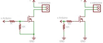
Switch Connection
The simplest way to connect a generator is using a switch. The switch operates in three positions. In the initial position, the object is connected to a centralized power grid, without the participation of a gas generator.
When the switch moves to the next position, the object is completely de-energized. The next time you turn the switch, the power to the home network switches to a backup source - a gas generator.
Keep in mind that if the total power of all consumers is 6 kilowatts, then the switch must support at least 30 Amps.
Brushless generator. Design and principle of operation
Brushless generators differ significantly from generators with a beak-shaped magnetic system.
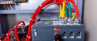
The generator shown in the figure uses an integrated voltage regulator. The stator 8 of the generator has grooves in which the stator winding coils are located, secured there with groove wedges. The phase coils are connected to each other in series, and the phases are connected in a triangle or, with a five-phase design, in a pentagon. The stator core is sandwiched between two covers - the back 2, made of aluminum alloy, and the front 1. The front cover is made of steel, since it is a magnetic circuit (conducts the magnetic flux formed by the stationary excitation winding located on the generator inductor sleeve). The inductor 10 is pressed with a flange to the end of the front cover 1.
In a brushless valve generator with a fixed excitation winding (inductor generator), the rotor is a multi-beam steel sprocket mounted on a shaft. The field winding is coaxial with the rotor and fixed in a steel cover. A sleeve 9 is placed on the generator rotor shaft, into which the magnetic flux from the inductor sleeve passes through an additional air gap; rotor package sprocket 6 with six teeth, made of steel sheets; aluminum flange 7, in the protrusions of which, located between the teeth of the rotor package, permanent magnets are filled. These magnets, in addition to increasing the power of the generator, ensure its reliable self-excitation, i.e., the ability of the generator to operate when the battery is disconnected.
The bearing shield 12 of the generator is made of aluminum alloy. The back cover 2 is secured with pins. The rectifier unit 4 is located in the internal cavity of the rear cover 2 and is secured to it with three insulated bolts. The voltage regulator unit 5, containing an integral voltage regulator and an adjusted resistor, is located on the outer surface of the back cover and is covered with a plastic casing.
Rice. Brushless generator: 1 – front cover; 2 – back cover; 3 – casing; 4 – rectifier block; 5 – voltage regulator block; 6 – rotor package; 7 – flange with permanent magnets; 8 – stator; 9 – rotor bushing; 10 – inductor; 11 – excitation winding; 12 – bearing shield
The magnetic flux passing from the rotor to the stator through the teeth of the rotor sprocket is large, and in the spaces between the teeth (through the air) it is small. When the rotor rotates, either the teeth or the cavities of the rotor appear in succession opposite the coils of the stator phase windings. The magnetic flux penetrating them changes in magnitude, and an alternating voltage appears in the coils. To increase the degree of change in the magnetic flux and, consequently, increase the power of the generator, permanent magnets are fixed in the cavities of the rotor sprocket.
Source
Replacement and removal of the electric generator
The generator on a VAZ car is removed either for complete replacement in case of failure or to carry out repair work to replace faulty parts. To perform dismantling, prepare a standard set of tools; it is advisable to drive the car into the inspection hole.
- Disconnect the battery.
- Remove the protective rubber cap from terminal “30” and unscrew the nut and remove it from the wire stud.
- Disconnect the block with wires from the generator connector.
- We loosen the tightening of the generator to the adjusting bar, then lift it all the way up to the cylinder block and remove the belt from the pulleys.
- Completely unscrew the bolt securing the adjusting bar to the cylinder block, then from the bottom of the car unscrew the 2 bolts securing the lower bracket to the block and remove the generator, pulling it out of the engine compartment.
What types of generators are there?
Many people think that generators and uninterruptible power supplies are mutually interchangeable and identical. But that's not true. UPS are devices that provide current only for a while. Their work is just enough to save important information on the computer, for example. The generator can produce electricity many times longer.
There is another device that many also confuse with generators. These are voltage stabilizers. They equalize the voltage if surges occur in the network. Stabilizers protect equipment from sudden changes in network voltage, thereby extending the service life of electrical appliances.
Before answering the question of how to connect a generator to the home network, you need to understand which generators can be connected to the home network.
There are three main types of generators based on engine type:
- gasoline;
- diesel;
- gas.
A gasoline generator is used only for a short time; its operation is not suitable for long-term loads. If the main power source is, then gasoline units should be purchased only to maintain the operation of the devices for a short time (up to 12 hours), if there are frequent network outages.
The diesel generator is the most powerful unit. This is, in fact, a diesel station that can continuously generate electricity, or be used as a backup generator for lighting the house.
Gas generators consume the least amount of fuel, which is why they are considered the most economical generators. They can operate either from a gas cylinder or from a gas main.
Also, both gas and gasoline can be used as fuel in one generator - with the ability to switch. They are called dual-fuel.
There are two more types of generators - inverter and welding. Both gas and gasoline can be used as fuel.
Inverter generators have a distinctive feature - performance adjustment. For example, during a power outage, all appliances in the house are connected to the generator. If you turn off any device, automatic performance adjustment will work, and the generator itself will reduce the load.
Welding generators are designed to power welding machines, mainly manual ones.
The number of phases and the cooling system also depend on the type of generator.
Based on the number of phases, generators are divided into single-phase (output voltage 220 V) and three-phase (380 V). The first are used in residential buildings where there is only one power and ground line. A three-phase generator provides power via three power lines, with one grounding line.
Generators use air or liquid cooling. The first is used on generators or power plants whose power does not exceed 6 kW. Liquid cooling is installed on more powerful generators, the number of engine hours of which is about thirty thousand. It is better to buy such generators on official websites or in specialized stores to prevent interference with the device by unscrupulous sellers.
How to connect a three-phase generator?
In the case of using a switch, a winding is required for each phase separately, that is, a jumper from one phase to another.